Note: Descriptions are shown in the official language in which they were submitted.
pIRP
CA 02843478 2014-01-29
1
FRAUNHOFER-GESELLSCHAFT...e.V.,
Astro- und Feinwerktechnik Adlershof GmbH
117PCT 1111
Method for manufacturing a mirror comprising at least
one cavity and optical mirror
The invention relates to a method for manufacturing a
light weight optical mirror or .a monolithic mirror
with internal cooling channels, to a corresponding
optical mirror and to an optical device.
In a variety of applications in the field of optics
there is demand for light weight optical components,
in particular for light weight optical mirrors. For
instance, an optical mirror of a space telescope
should exhibit a reduced weight to minimize transpor-
tation costs and to reduce mechanical distortions
caused by high inertial forces. The same applies to
optical mirrors which are regularly exposed to large
accelerations during their operation as e.g. in scan-
ning experiments.
In order to reduce the weight of an optical mirror it
CA 02843478 2014-01-29
2
is known from the prior art to manufacture the opti-
cal mirror from a material featuring a low density
and thus a low weight while at the same time provid-
ing a sufficient degree of mechanical rigidity and
stiffness, such as e.g. aluminium and beryllium.
Another way of reducing the weight of an optical mir-
ror consists in making the mirror at least partially
hollow. To this end the mirror can be produced from a
variety of separately manufactured components. How-
ever, joining separate components together usually
complicates the manufacturing process. Furthermore,
even slight deviations from a calculated shape of the
separate components can cause disadvantageous me-
chanical stresses within an assembled structure of
the mirror. During the life cycle, also the long term
stability and thermal conductivity are negatively in-
fluenced by joints.
Another reason for proving at least one cavity within
a mirror body may be the need of cooling channels.
The aforementioned disadvantages can be partially
circumvented by e.g. casting the mirror as a solid
block and by introducing cavities into the clock via
cutting, drilling or grinding. However, as the cavi-
ties are formed by accessing the block from its out-
side, the cavities cannot be given any desired shape.
In particular, an arrangement of the cavities is not
independent of a shape of the block surface. There-
fore, it is generally not possible to form the cavi-
ties such that the resulting structure features an
ideal ratio of mechanical stiffness over weight.
In a slightly more advantageous casting method, the
cavities are formed during the casting process by in-
1
CA 02843478 2014-01-29
3
troducing a packing into a corresponding mould used
for the casting of the mirror. However, removing the
packing from the mirror after the casting process can
be labour-intensive and costly.
Thus, it is an objective of the present invention to
suggest a method for producing a light weight optical
mirror wherein the mirror is manufactured such that
it features both a high degree of mass reduction and
a high degree of mechanical stiffness and/or at least
one cavity which can be used as a cooling channel and
(-) wherein the method comprises a preferably small num-
ber of production steps and can be implemented at
preferably low cost. Furthermore, it is an objective
of the present invention to design a corresponding
light weight optical mirror or a mirror comprising at
least one cooling channel with the aforementioned ad-
vantageous features.
This objective is achieved by a method for producing
a light weight optical mirror or for producing a
monolithic mirror comprising at least one cooling
channel and by an optical mirror according to the in-
dependent claims. Advantageous embodiments of the in-
vention are described in the dependent claims.
According to the invention a method for manufacturing
a light weight optical mirror or for manufacturing a
monolithic mirror comprising at least one cooling
channel comprises
forming a mirror body by
= iteratively depositing a metallic powder in lay-
ers and
=
CA 02843478 2014-01-29
4
= applying, for each of the layers, heat at least
in a subarea of this layer, thereby fusing or
sintering the powder in this subarea and bonding
it to a previously deposited layer,
the powder remaining in an unfused state in at least
one region, and the method further comprises
= forming at least one cavity within the mirror
body by removing the unfused powder from said
region and
; producing a mirror surface at a closed surface
of the mirror body by means of machining and/or
figuring and/or coating.
By this method thus the mirror body is formed from
the metallic powder in a primary shaping process in
such a way that the resulting mirror body is at least
partially hollow. Thus, a high degree of mass reduc-
tion is realized in a comparatively simple way.
Forming the at least one cavity within the mirror
body by removing the unfused powder from said region
results in the mirror body having a particularly low
weight compared to mirror bodies without cavities.
Consequently, inertial forces exerted on the optical
mirror due to accelerations are particularly small,
resulting in a smaller distortion of the mirror due
to the inertial force resulting from an acceleration.
Also, less material is needed for producing the mir-
ror leading to lower production costs. The cavity or
each of the cavities can be a continuous volume, at
least 70 percent, preferably at least 90 percent,
most preferably at least 95 percent of a surface of
this volume being enclosed by a continuous part of
the mirror body.
3
CA 02843478 2014-01-29
Forming the mirror body by iteratively depositing the
metallic powder in layers and by applying, for each
of the layers, heat at least in the subarea of the
5 corresponding layer, thereby fusing or sintering the
powder in this subarea and bonding it to a previously
deposited layer is a fast and highly flexible way of
shaping the mirror body. Notably, the mirror body and
the cavity within the mirror body can be easily given
any desired three dimensional shape by determining
I the subarea in each layer where the metallic powder
is to be sintered or fused and by determining the re-
gion where the metallic powder is to remain in the
unfused or unsintered state. In particular, a shape
of a surface of the mirror body can be chosen virtu-
ally independent of the shape of the at least one
cavity. This is not the case if the at least one cav-
ity is worked into e.g. an existing metal block, as
it is known from the prior art. As the shape of the
surface of the mirror body generally has a great in-
fluence on the overall stiffness of the mirror body,
application of the presently proposed method yields
an optical mirror combining a high degree of mass re-
( ) duction with a high level of mechanical stiffness.
Typically, the three dimensional shape of the mirror
body is stored as a three dimensional CAD model and
can be accessed by a control unit capable of control-
ling the application of heat in the subareas of the
different layers. The subareas then correspond to two
dimensional cross sections of the CAD model. Thus, a
mirror body with a different three dimensional shape,
e.g. with a different configuration of the at least
one cavity or with a differently shaped surface, can
easily be formed without the need to modify a forming
CA 02843478 2014-01-29
6
or shaping apparatus. All that is required to produce
a differently shaped mirror body is to store a dif-
ferent three dimensional CAD model. Therefore, the
presently described method is highly flexible and can
be easily automated.
Forming the cavity by removing the metallic powder
from said at least one region where the powder re-
mains in the unfused state is simpler and cheaper to
implement than e.g. drilling or milling the cavity
out of a solid block, as is known from the prior art.
r" Preferably, the fusing or sintering is carried out in
such a way that the at least one region can be ac-
cessed from outside the mirror body or outside the
mirror so that the powder can be easily removed to
form the cavity or the cavities.
Reducing the mass of the optical mirror by introduc-
ing the at least one cavity within the mirror body
makes the optical mirror less prone to changes in
temperature. Evidently, the light weight optical mir-
ror is easy to transport and/or to manage, as forces
and/or an amount of energy required to move the mir-
ror can be kept small.
The metallic powder need not be made entirely of
metal but may comprise other non metallic, preferably
non organic components or additives. Fusing and/or
sintering the powder may include partially and/or
completely melting individual grains of the powder.
A thickness of the different layers before the appli-
cation of heat in the subarea may range between 10 pm
and 200 pm, preferably between 50 pm and 100 pm. The
subarea denotes a three dimensional volume which ex-
tends over the entire thickness of a given layer.
1
CA 02843478 2014-01-29
7
Typically, a fusing volume of the subarea, inside
which heat is applied at a given instant, has a di-
ameter which is equal to or slightly larger than the
thickness of the different layers. This way the fus-
ing and/or melting and/or sintering of the powder is
carried out most effectively, as virtually all the
heat deposited in the subarea at a given instant is
used to fuse and/or melt and/or sinter the powder and
to fuse and/or melt and/or sinter it to a previously
deposited layer. Preferably, a size of the fusing
I volume may be varied during the forming of the mirror
body. Thereby, a required accuracy, i.e. spatial
resolution with which the mirror body is formed can
be adjusted locally so that the forming of the mirror
body can be carried out at a desired speed and/or a
desired accuracy. Of course, heat may be applied in a
plurality of fusing volumes simultaneously, thereby
significantly speeding up the primary shaping proc-
ess.
Depending on an application for which the optical
mirror is produced, a typical size of the optical
mirror and/or a typical size of the mirror body may
I 25 range from a few centimetres, as e.g. in scanning
mirrors designed for fast imaging applications, up to
several metres, as e.g. in telescopes.
A stiffness of the mirror body can be advantageously
increased by forming the mirror body such that a rear
surface of the mirror body is completely closed or
nearly completely closed, the rear surface being ar-
ranged on a side of the mirror body averted from the
;
mirror surface. For instance, the rear surface can
;
form a continuous surface of the mirror body, with
holes or recesses which perforate the rear surface
?
CA 02843478 2014-01-29
8
amounting to less than 20 percent, preferably less
than 10 percent, most preferably less than 5 percent
of the rear surface, i.e. of the rear surface includ-
ing an area of the holes or recesses within the rear
surface. By closing or nearly closing the rear side
of the mirror body a resistance of the mirror body to
mechanical bending and/or deflection is enhanced, as
expressed by an increased second moment of area of
the mirror body. Additionally, forming the mirror
body such that the rear surface of the mirror body is
closed prevents a shift of a centre of mass of the
mirror body and/or of the optical mirror towards the
optical surface of the mirror or towards the closed
surface of the mirror body at which the optical sur-
face is to be formed. Also, the closed rear surface
of the mirror body may facilitate handling the mirror
body and/or the optical mirror during production
and/or during operation of the optical mirror and/or
the mirror body.
In a further advantageous embodiment of the invention
the cavity is formed such that it comprises at least
a section of a neutral axis of the mirror body,
wherein the neutral axis is defined as an axis of the
mirror body along which longitudinal stresses or
strains are minimal as the mirror body is bent or
distorted. Preferably, the cavity comprises the neu-
tral axis completely. A region of the mirror body
which comprises the neutral axis of the mirror body
yields a minimal contribution to the second moment of
area of the mirror body, i.e. to the resistance of
the mirror body to mechanical bending or deflection.
Thus, forming the cavity such that it comprises at
least a section of the neutral axis of the mirror
body reduces the mass of the mirror body while mini-
mally decreasing its stiffness. Thus, forming the
CA 02843478 2014-01-29
9
cavity to comprise the neutral axis yields a mirror
body with an ideal ratio of stiffness over mass.
The above mentioned advantages associated with reduc-
ing the mirror body's mass are particularly pro-
nounced if the at least one cavity is formed such
that it amounts to between 50 and 90 percent by vol-
ume of the optical mirror. Equivalently, the cavity
is advantageously formed such that it amounts to be-
tween 50 and 90 percent by volume of the mirror body.
(- The cavity or each of the cavities will have at least
one opening for removing the unfused powder. Advanta-
geously, the cavity or each of the cavities may be
formed such that the cavity or each of the cavities
has at least two distinct openings at a surface of
the mirror body. This way, removing the unfused pow-
der from the at least one region of the mirror body
is greatly simplified.
According to another advantageous embodiment of the
invention the at least one cavity is formed to com-
prise a channel or a system of channels for conduct-
ing a liquid or a gas. The liquid or gas, which may
be utilized as a coolant for regulating a temperature
of the optical mirror during operation, may be easily
circulated through the cavity or through some or each
of the cavities. Thus, the at least one cavity may,
in particular be a coolant channel or several cooling
channels.
Several cavities which are connected to one another
via connecting channels and/or recesses may be con-
nected to the same at least two distinct openings at
the surface of the mirror body. Having a coolant cir-
culating through the cavity or the cavities is par-
1
1
CA 02843478 2014-01-29
ticularly advantageous for applications of the opti-
cal mirror where large amounts of heat must be dissi-
pated, e.g. in applications where the optical mirror
is exposed to particularly strong irradiation.
5
A particularly simple and effective way of removing
the unfused powder comprises blowing out the at least
one cavity. Preferably, the powder is blown out by
means of compressed air and/or by means of a combina-
10 tion of a gas and an abrasive medium. Blowing out the
cavity is most effective if the cavity or each of the
cavities has at least two distinct openings at the
surface of the mirror body. Adding the abrasive me-
dium, such as grains of sand or metal, to the corn-
pressed air or gas may smoothen a surface of the cav-
ity or of the cavities for further processing.
In advantageous embodiments of the invention the me-
tallic powder is deposited in a composition compris-
ing aluminium and silicon or in a composition com-
prising aluminium and beryllium or in any aluminium
alloy composition. Aluminium has a low density while
at the same time being mechanically stiff. A fitness
of a composite of aluminium and silicon for welding
and/or sintering and/or fusing is known to increase
with increasing silicon content.
It may be advantageous to vary the composition of the
metallic powder in the course of the forming of the
mirror body. E.g. a silicon component of the metallic
powder may be varied between 27 and 87 percent by
1
weight. The composition of the metallic powder may be
1
varied within a given layer and/or between different
0
layers. By locally varying the composition of the me-
tallic powder a coefficient of thermal expansion
(CTE) of the mirror body can vary locally, i.e. the
CA 02843478 2014-01-29
11
CTE of the mirror body can take on different values
in different parts of the mirror body. The composi-
tion of the metallic powder can be varied such that
the CTE of the mirror body is adjusted to a local ge-
ometry of the mirror body. E.g. the CTE can be made
smaller in areas of the mirror body which most
strongly and/or most directly affect a shape of the
optical surface. Also, the local composition of the
metallic powder can be varied according to different
levels of mechanical stress which different parts of
the mirror body endure during handling and/or opera-
(-1 tion of the optical mirror. Advantegeously, the local
CTE of the mirror body is varied such that a location
of a focal point of the mirror relative to the mirror
is automatically adjusted and/or controlled as the
temperature of the mirror changes. Preferably, the
location of the focal point of the mirror relative to
the mirror is controlled such that it remains con-
stant under temperature variations.
A further advantageous embodiment of the invention
provides that the metallic powder has a grain size of
between 1 pm and 100 pm. A small grain size allows
the mirror body to be formed particularly homogene-
(
ously even if the individual grains are not com-
pletely melted. Also, a small grain size facilitates
the fusing and/or melting and/or bonding process as a
ratio of surface over volume of the powder is in-
creased.
The heat can be applied particularly effectively and
flexibly by means of a laser beam. Lasers providing
laser light at a wide range of different wavelengths
and intensities are readily available as are optical
components for manipulating the laser beam. Manipu-
lating the laser beam can comprise shaping and/or
CA 02843478 2014-01-29
12
guiding and/or scanning and/or focussing the laser
beam and/or controlling the laser power and/or con-
troling an intensity of the laser beam as a function
of time.
The laser beam can be focused, in each of the layers,
to a spot or to a focal volume with a diameter of be-
tween 10 pm and 500 pm, preferably of between 50 pm
and 200 pm. At smaller spot sizes higher intensities
of the laser beam within the spot or within the focal
volume can be reached with a given maximum power pro-
,
( vided by the laser. Preferably, spatial dimensions of
the focal volume are adjusted to the thickness of the
layer which is being fused and/or sintered at a given
instant. The spatial dimensions of the focal volume
can determine the spatial accuracy, i.e. the spatial
resolution with which the mirror body is formed,
smaller spatial dimensions of the focal volume pro-
viding higher spatial resolution.
The laser beam can be applied in a pulsed mode or in
a continuous wave mode. Operating the laser in the
pulsed mode can provide particularly high peak values
of a laser intensity, thereby facilitating the fusing
and/or sintering of the metallic powder. A pulse du-
ration of the laser pulses can be smaller than 5 ns,
preferably smaller than 100 ps, more preferably
smaller than 10 ps, whereby higher peak intensities
can be provided at shorter pulse durations at a given
maximum power of the laser beam.
A pulse repetition rate can be at least 10 kHz, pref-
erably at least 1 MHz, more preferably at least 50
MHz, whereby a higher repetition rate allows more en-
ergy to be deposited for fusing the powder within a
given time interval, thereby speeding up the forming
CA 02843478 2014-01-29
13
process. An average power of the laser beam can be at
least 10 W, preferably at least 100 W, more prefera-
bly at least 1 kW. A peak intensity of the laser beam
can be at least 10 kW/mm2, preferably at least 100
kW/mm2, more preferably at least 10 MW/mm2. A wave-
length of the laser light emitted by the laser can
range between 350 mm and 12 pm. Preferably, the wave-
length is adapted to an absorption spectrum of the
metallic powder.
It is particularly advantageous if one or several or
preferably all of the above mentioned laser parame-
ters are configured to be varied in the course of the
forming of the mirror body. This way the fusing
and/or sintering of the metallic powder and thus ma-
terial properties of the mirror body in different
parts of the mirror body can be precisely controlled.
In a further advantageous embodiment of the invention
producing the mirror surface comprises coating at
least the closed surface with an additional layer,
the additional layer preferably furthermore covering
the entire mirror body and/or a cavity surface of the
at least one cavity. The additional layer can be cho-
sen to have certain desired optical properties such
as a desired minimum reflectivity or a desired re-
flectivity spectrum. The additional layer can be re-
quired if the top layer of the mirror body is porous
while a dense and pit-free optical surface is neces-
sary for the application. In this case, the addi-
tional layer is preferably thicker than the depth of
the pores and machined and figured within the layer
thickness to fulfil the optical specifications re-
garding shape and roughness. The additional layer can
be the substrate for further additional layers such
as reflectivity coatings, protection coatings or mul-
CA 02843478 2014-01-29
14
tilayer coatings. Also, the additional layer can be
used as a protection of the mirror body material. The
surface of the mirror body can e.g. be made more
chemically inert, thereby preventing corrosion of the
mirror body. If the cavity or the cavities are in-
tended to conduct a coolant, coating the cavity sur-
face with the additional layer can protect the mirror
body material from the coolant.
In order to reduce mechanical distortions due to
changes in temperature, it is particularly advanta-
(-
geous if a composition of the mirror body at the
closed surface and a composition of the additional
layer are chosen such that an absolute value of a
difference between a coefficient of thermal expansion
of the closed surface and a coefficient of thermal
expansion of the additional layer is smaller than
than 5 x 10⁻⁶ K-1, preferably smaller than 0,5 x 10⁻⁶
K-1. In this way, the athermal behaviour of the mir-
ror can be increased and mechanical stresses which
cause distortions of the mirror can be reduced.
A further advantageous aspect of the invention pro-
vides that the additional layer comprises a composi-
tion of nickel and phosphor or the additional layer
comprises amorphous silicon. Preferably, also the
nickel-phosphor composition is amorphous. Particu-
larly in the case of the mirror body comprising alu-
minium and silicon a CTE of the nickel-phosphor corn-
posite of the additional layer can be easily and ad-
vantageously adapted to the CTE of the mirror body,
thereby inhibiting temperature-induced mechanical
stresses and/or distortions.
The coating of the closed surface and/or of the sur-
face of the mirror body can be carried out with par-
5
CA 02843478 2014-01-29
ticularly high precision if the coating comprises ap-
plying one of a galvanic process, a physical vapour
deposition process and a chemical vapour deposition
process. The coating can also comprise slip-casting a
5 ceramic material. Preferably, the coating is carried
out such that the additional layer has a thickness of
between 1 pm and 700 pm. The cited coating techniques
provide accurate control of a chemical and/or physi-
cal composition and/or of the thickness of the addi-
10 tional layer.
( The mirror surface can be given a desired shape with
high accuracy if producing the mirror surface com-
prises machining or figuring the closed surface
15 and/or machining or figuring an additional layer de-
posited on the closed surface. In particular, the ma-
chining or figuring may be employed during various
stages of the production process. E.g. the closed
surface and/or the additional layer deposited on the
closed surface may be machined or figured repeatedly
with increasing accuracy.
The machining or figuring can be carried out to draw
a shape of the closed surface and/or of the addi-
c.
tional layer deposited on the closed surface close to
a desired shape determined e.g. from an optical de-
sign model of the closed surface and/or of the addi-
tional layer. E.g. producing the mirror surface can
be carried out such that a shape of the mirror sur-
face is one of planar, spherical, aspherical, concave
and convex. Alternatively, the mirror surface can be
freely shaped and, in particular, be not rotationally
symmetric (freeform).
Preferably, before coating the closed surface with
the additional layer a deviation of the shape of the
1
CA 02843478 2014-01-29
16
closed surface from the desired shape is less than 5
pm, more preferably less than 1 pm, whereby the maxi-
mum deviation, i.e. the desired accuracy can be ad-
justed depending on the thickness of the additional
layer. E.g. the deviation can be larger for larger
values of the thickness of the additional layer.
Producing the mirror surface can be carried out with
high accuracy, fast and flexibly if it comprises one
of polishing, grinding, turning, diamond turning,
milling, diamond milling and ion beam figuring (IBF).
A further advantageous implementation of the claimed
method comprises a heat treatment of the mirror body
during and/or after the forming of the mirror body
for reducing mechanical stresses within the mirror
body. The heat treatment can comprise exposing the
mirror body to temperatures above 150 C, above 400
C, above 600 C or above 800 C, depending on a
melting temperature of the metallic powder used. E.g.
the heat treatment can comprise placing the mirror
body in a furnace.
An optical device comprising the optical mirror which
is produced by means of the above described method is
preferably designed as being a telescope or a light
source or a beam shaping optics or a collector mirror
in an EMI light source or in any other light source.
A light weight optical mirror which can be manufac-
tured by the method described above comprises a mono-
lithic metallic mirror body and a mirror surface at a
closed surface of the mirror body, the mirror body
having a closed rear surface averted from the mirror
surface, wherein the mirror surface and the rear sur-
face are connected by a plurality of walls, the walls
CA 02843478 2014-01-29
17
enclosing a plurality of cavities, each of the cavi-
ties being connected to at least two distinct open-
ings at a surface of the mirror body.
In an advantageous embodiment of the light weight op-
tical mirror the walls are arranged in a honeycomb-
like structure. Arranging the walls in a honeycomb-
like structure yields a high level of mass reduction
while providing the mirror with a high degree of sta-
bility and stiffness.
( The invention will now be described by way of example
with reference to the accompanying drawings in which
Figs. la-d are schematics illustrating different
stages of forming a metallic mirror
body of a light weight optical mirror
in a laser sintering process,
Fig. 2 is a schematic depicting the forming
of cavities within the mirror body by
blowing out unsintered metallic pow-
der from unsintered regions within the
mirror body,
(,) 25
Fig. 3 is a schematic showing the mirror body
in a furnace,
Fig. 4 is a perspective drawing of the mirror
body,
Fig. 5 is a schematic demonstrating machining
of a closed surface of the mirror
body,
Fig. 6 is a schematic showing the mirror body
CA 02843478 2014-01-29
18
in an electroplating bath and
Fig. 7 is a schematic of a light weight opti-
cal mirror with the same mirror body,
Fig. 8 is a schematic of a detail of the
light weight optical mirror shown in
Fig. 7,
Fig. 9 is a reflector telescope comprising a
light weight optical mirror of the
( 1 type shown in Fig. 7,
Fig. 10 is a perspective drawing of a mirror
in a second embodiment,
Fig. 11 is a cross-sectional view of the mir-
ror shown in Fig. 10 and
Fig. 12 is a top view of the same mirror.
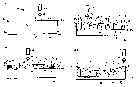
Figs. la-d show a mould 20 inside of which a mirror
body 2 (Figs. lb-d) of a light weight optical mirror
1 (see Figs. 7, 8) is formed from metallic powder in
(_)
a laser sintering process. The forming of the mirror
body 2 is carried out according to a three dimen-
sional CAD model of the mirror body 2 which is stored
in a control unit (not shown). The mould 20 comprises
a base 21, outer walls 22 and a lifting platform 23
which is arranged horizontally within the mould 20
and which can be moved up and down along a vertical
z-direction 24. In Figs. la-d the lifting platform 23
is shown at different vertical positions 24a, 24b,
24c and 24d with respect to the base 21. The outer
?
walls 22 and the lifting platform 23 enclose a vari-
able storage volume, a variable depth 25 of which is
1
1
CA 02843478 2014-01-29
19
shown in Figs. la-d. The storage volume is accessible
from an open upper side of the mould 20.
At a beginning of the laser sintering process, shown
in Fig. la, the lifting platform 23 is positioned at
the initial vertical position 24a and an initial
layer 4a of the metallic powder is deposited evenly
on the lifting platform 23 by means of a powder depo-
sition mechanism (not shown). The metallic powder
forming the initial layer 4a is a composition of alu-
minium and silicon with an average grain size of 50
pm. Of course the metallic powder could comprise
other metals or compositions of metals, such as e.g.
a composition of aluminium and beryllium. Also, non
metallic additives may be added to the metallic pow-
der. In the course of the forming of the mirror body
2 a silicon component of the metallic powder is var-
ied between 30 and 75 percent by weight. A thickness
of the initial layer 4a is 100 pm. Within the initial
layer 4a individual grains of the metallic powder are
partially and/or completely melted and fused or sin-
tered together by scanning a laser beam 15 emitted by
a laser 27 over the initial layer 4a, thereby forming
a closed surface 10 of a closed rear wall 31 of the
(_)
mirror body 2 (Figs. lb-d).
At a given instant, a lens 28 focuses the laser beam
15 within the initial layer 4a to a focal spot 16
with a diameter of about 200 pm, thereby fusing the
individual grains of the metallic powder over the en-
tire thickness of the initial layer 4a. The laser 27
emits pulses of infrared laser light at a wavelength
of 1060 nm, an individual laser pulse having a dura-
tion of 100 Ps and the pulses being emitted at a rate
of 1 MHz. An average beam power of the laser beam 15
;
is 100 W, resulting in a pulse energy of an individ-
CA 02843478 2014-01-29
ual laser pulse of 100 10.
After the initial layer 4a has been fused by means of
the laser beam 15, the lifting platform 23 is lowered
5 by slightly less than 100 pm to a next vertical posi-
tion (not shown) and a second layer of the metallic
powder is deposited via the powder deposition mecha-
nism. The laser beam 15 is again scanned over the
second layer, thereby fusing or sintering individual
10 grains of the metallic powder of the second layer and
bonding the second layer to the initial layer 4a de-
.
! posited in the previous, i.e. in the initial step.
Subsequently, this process is repeated until the mir-
15 ror body 2 is build up, layer by layer, wherein the
laser beam 15 fuses or sinters the metallic powder in
subareas of the different layers and bonds each of
these subareas to a previously deposited layer. The
subareas, inside which the metallic powder is at
20 least partially fused or sintered, may form only a
part of the respective layer. In this case, the me-
tallic powder is not fused or bonded outside the su-
barea of the respective layer. The subareas may also
comprise the entire layer. The different layers cor-
respond to two-dimensional sectional areas of the
three-dimensional CAD model of the mirror body 2. The
control unit reads out the data defining the three-
dimensional CAD model of the mirror body 2 and con-
trols the movement of the laser 27 over the subarea
of a given layer according to that data.
Fig. lb illustrates the laser sintering process after
depositing a plurality of layers of the metallic pow-
der and sintering or fusing them in the corresponding
subareas of the previously deposited layers, thereby
forming a lower part of the mirror body 2. Here and
1
1
CA 02843478 2014-01-29
21
in all of the following recurring features are indi-
cated with identical reference signs. Until the in-
stance of the laser. sintering process shown in Fig.
lb the rear wall 31, parts of inner walls 19 and
parts of a side wall 45 of the mirror body 2 have al-
ready been formed via fusing of the metallic powder.
The lifting platform 23 is positioned at the vertical
position 24b and a layer 4b of the metallic powder
has been deposited on top the previously applied lay-
ers, the layer 4b having a homogeneous thickness of
120 pm, i.e. the layer 4b being slightly thicker than
the initial layer 4a. The average grain size of the
metallic powder used to form the layer 4b in Fig. lb
is 80 pm and the silicon component of the metallic
powder used to form the layer 4b is 50 percent by
weight. I.e. with respect to the forming of the ini-
tial layer 4a, the composition and the grain size of
the metallic powder used to form the layer 4b have
been altered slightly. Also, the diameter of the fo-
cal volume of the laser beam 15 has been decreased to
150 pm by changing optical properties of a beam path
of the laser beam 15 (not shown). As a result of this
parameter change a part of the mirror body 2 which is
formed by fusing and bonding a subarea 5b of the
layer 4b has a CTE and a hardness different from a
CTE and a hardness of the closed rear wall 31 of the
mirror body 2.
Fig. lb further illustrates that the metallic powder
remains in an unfused state in regions 6 in which the
metallic powder has not been sintered or fused, e.g.
by temporarily switching off or blocking the laser
beam 15 during the scanning or moving of the laser
beam 15. Also, it can be seen from Fig. lb that the
subarea 5b amounts to only a fraction of the layer
4b, regions of the layer 4b lying outside the subarea
CA 02843478 2014-01-29
22
5b constituting an uppermost layer of the unsintered
regions 6. The fused subarea 5b forms a section of
the inner walls 19 of the mirror body 2, the inner
walls 19 and the side wall 45 being connected to the
closed rear wall 31 of the mirror body 2 and the in-
ner walls 19 separating the unsintered regions G.
Fig. lc depicts the laser sintering process at yet a
later step. With respect to the step described with
respect to Fig. lb the lifting platform 23 has been
further lowered to the vertical position 24c. An av-
erage grain size of the metallic powder forming a
newly deposited layer 4c is 70 pm and a silicon com-
ponent of the metallic powder forming the layer 4c is
65 percent by weight. Of course it is also possible
to vary the composition of the metallic powder within
a given layer of the deposited metallic powder. In a
subarea Sc of the layer 4c the laser beam 15 fuses or
sinters the metallic powder and bonds the subarea 5c
to a previously deposited layer, thus adding another
layer to the mirror body 2. The subarea 5c in Fig. 1c
forms part of a closed front wall 32 of the mirror
body 2. Outside the subarea Sc of the layer 4c the
metallic powder of the layer 4c is not sintered,
forming again an uppermost layer of the unsintered
regions 6.
Fig. id shows a final stage of the laser sintering
process. With respect to Fig. lc the lifting platform
23 has been further lowered to the final vertical po-
sition 24d. While the metallic powder in the regions
6 is not sintered or fused or bonded, the fused su-
bareas of the various layers form the monolithic me-
tallic mirror body 2. The mirror body 2 comprises the
closed rear wall 31, the concave closed front wall
32, the inner walls 19 and the side wall 45, the in-
CA 02843478 2014-01-29
23
ner walls 19 and the side wall 45 connecting the rear
wall 31 and the front wall 32. The front wall 32 is
concluded by a closed surface 9 of the metallic mir-
ror body 2.
Fig. 2 shows the forming of a plurality of cavities 7
within the mirror body 2. The cavities 7 are formed
by removing the unfused metallic powder from the
unsintered regions 6 (Fig. 1d). I.e. the cavities 7
comprise those unsintered regions 6 lying within the
mirror body 2. The removing of the unsintered metal-
lic powder is carried out by blowing out the unsin-
tered metallic powder from the regions 6 using com-
pressed air 14, which is provided by a movable nozzle
46. Equivalently, the nozzle 46 could provide any
other compressed gas for blowing out the metallic
powder from the regions 6, e.g. compressed nitrogen.
Advantageously, an abrasive medium such as grains of
sand or metal could be added to the compressed air 14
or to the compressed gas.
Blowing out the cavities 7 by means of the compressed
air 14 is simplified by the fact that during the sin-
tering process described above each of the cavities 7
is shaped or formed in such a way that it has and/or
is connected to at least two distinct openings 12 at
a surface 13 concluding the side wall 45 of the mir-
ror body 2. The cavities 7 are described in greater
detail with respect to Fig. 4.
Notably, the mirror body 2 is shaped in such a way
that the rear wall 31 and the front wall 32 of the
mirror body 2 completely seal the mirror body 2 on
their respective sides of the mirror body 2. In other
words, the mirror body 2 features a closed surface 9
concluding the front wall 32 of the mirror body and a
CA 02843478 2014-01-29
24
closed rear surface 10 concluding the rear wall 31 of
the mirror body, the closed surface 9 and the closed
rear surface 10 lending the mirror body 2 a particu-
larly high degree of stiffness and stability. In an
alternative embodiment of the presently described
mirror body 2, holes can be provided in the rear wall
31 and/or the front wall 32 of the mirror body 2,
these holes, however, amounting to less than 20 per-
cent, preferably less than 5 percent of the rear sur-
face 10 of the rear wall 31 or of the closed surface
9 of the front wall 2 of the mirror body 2.
In the embodiment described here, a thickness of the
front wall 32, a thickness of the rear wall 31 and a
thickness of the side wall 45 are each approximately
3 mm to 10 mm. A thickness of the inner walls 19 is
approximately 1 mm to 3 mm. A diameter 34 of the mir-
ror body 2 is about 400 mm. At the side wall 45 a
maximum height 35 of the mirror body 2 is approxi-
mately 15 mm to 150 mm. A density of the aluminium-
silicon composite from which the mirror body 2 has
been formed in the sintering process varies locally
between 2,1 g/cm3 and 2,7 g/cm3, parts of the mirror
body 2 which are under high mechanical stress being
formed to exhibit a higher local density than other
parts which are under lower mechanical stress. The
local density of the mirror body 2 is a function of
parameters such as the composition of the aluminium-
silicon composite, the grain size of the metallic
powder and the parameters of the laser beam 15 (Figs.
1a-d) such as the beam intensity, the diameter of the
focal spot 16 and a laser dwell time, wherein the
latter is a time interval during which the laser beam
15 stays at a given position while fusing and/or sin-
tering the metallic powder at that position.
CA 02843478 2014-01-29
After the cavities 7 have been formed the mirror body
2 is undergoing a heat treatment, as shown in Fig. 3.
To this end the mirror body 2 is placed in a furnace
47, the furnace 47 heating the mirror body 2 to a
5 temperature of below 500 C, which is still well be-
low the melting temperature of the aluminium-silicon
composite from which the metallic mirror body 2 has
been shaped in the sintering process. Due to the
heating of the mirror body 2 inside the furnace 47,
10 mechanical stresses within the mirror body 2 which
may build up during the primary shaping process of
the mirror body 2 are gradually reduced while an
overall structure of the mirror body 2 remains un-
changed.
Fig. 4 shows a three-dimensional transparent view of
a structure of the mirror body 2. All walls or sur-
faces of the mirror body 2 are depicted only by lines
delimiting the respective wall or surface. It can be
clearly seen that the mirror body 2 is approximately
cylindrical, the closed rear wall 31 having a circu-
lar shape. Furthermore, the inner walls 19 divide an
interior of the mirror body 2, i.e. a part of the
mirror body 2 enclosed by the completely closed front
wall 32, the likewise completely closed rear wall 31
and the side wall 45, into a plurality of cells or
compartments, the cells or compartments forming the
cavities 7. The inner walls 19 are arranged in a hon-
eycomb-like structure, thereby connecting the rear
wall 31 and the front wall 32. Neighbouring cavities
7 are connected via through holes 33 in the respec-
tive inner wall 19 separating the respective
neighbouring cavities 7. Each of the cavities 7 bor-
dering on the side wall 45 of the mirror body 2 is
further connected to an exterior of the mirror body 2
through one of the openings 12 piercing the side wall
a
CA 02843478 2014-01-29
26
45. In Fig. 4 only a subset of the cavities 7, the
side walls 19 and the through holes 33 are marked
with their corresponding reference sign for matters
of clarity.
The regular honeycomb-like structure of the inner
walls 19 and the fact that the inner walls 19 serve
as rigid bridges between the front wall 32 and the
rear wall 31 grant the mirror body 2 a high degree of
stiffness and stability. A surface area of the inner
walls 19 is a few square centimetres with an area of
the through holes 33 arranged in the inner walls 19
amounting to less than five percent of the surface
area of the respective inner walls 19 in which they
are arranged. Due to the nearly hyperbolic shape of
the front wall 32, the surface area of the inner
walls 19 decreases from the side wall 45 towards a
centre of the mirror body 2.
Due to the introduction of the cavities 7, a mass of
the mirror body 2 is significantly reduced as com-
pared to a solid, i.e. non-hollow body with an iden-
tically formed outer surface. In the present embodi-
ment of the mirror body 2 the cavities 7 are formed
such that a volume of the cavities 7 amounts to ap-
proximately 90 percent by volume of the mirror body
2, the volume of the mirror body 2 being given by the
volume enclosed by the mirror body's outer surfaces
9, 10 and 13. In addition, the cavities 7 have been
formed in such a way that they comprise at least a
section of a neutral axis of the mirror body 2,
wherein the neutralaxis is an axis of the mirror
body 2 along which longitudinal stresses or strains
are minimal as the mirror body 2 is bent or dis-
torted.
CA 02843478 2014-01-29
27
Figs. 5 and 6 illustrate different steps in the pro-
duction of a mirror surface 8 (see Fig. 8) at the
closed surface 9 of the front wall 32 of the mirror
body 2. Specifically, Fig. 5 demonstrates the process
of machining the closed surface 9 by means of a ma-
chining technology. Fig. 6 depicts the process of de-
positing on the closed surface 9, on the rear surface
10, on the surface 13 and on cavity surfaces 36 an
additional layer 17 (Fig. 7) in an electroplating
bath.
Fig. 5 shows the mirror body 2 mounted on a rotating
air bearing spindle, a tool holder 37 of a diamond
turning lathe with a diamond 38 arranged thereon and
a surface measuring device 39 with a measuring tip
40, the surface measuring device 39 being configured
to measure a constitution of the closed surface 9.
The tool holder 37 is moved over the closed surface 9
by a corresponding further control unit (not shown),
whereby a relative orientation of the tool holder 37
with respect to the closed surface 9 can be con-
trolled with a precision down to about 20 rim in all
spatial directions. In this manner the diamond turn-
ing lathe cuts, by means of the diamond 38, the
closed surface 9 with high precision giving the
closed surface 9 a desired shape, the desired shape
of the closed surface 9 being determined by the opti-
cal design model of the mirror body 2 stored in the
control unit.
Preferably, the diamond turning of the closed surface
9 is performed in a number of steps, a precision of
1
the turning process being increased between subse-
quent steps. After each of these steps the shape of
the closed surface 9 is measured using the surface
measuring device 39 and a result of this measurement
CA 02843478 2014-01-29
28
is compared with the desired shape of the closed sur-
face 9. Based on this comparison the control unit
which controls the movement and the orientation of
the tool holder 37 conducts another run, thereby
drawing the shape of the closed surface 9 closer to
the desired shape. For instance, in a first turning
step the closed surface 9 is machined with a preci-
sion of 3 pm, in a second step the closed surface 9
is machined with a precision of 1 pm and in a third
turning step the closed surface 9 is machined with a
precision of 300 nm. In variations of the presently
described embodiment of the invention, the machining
and/or figuring of the closed surface 9 could alter-
natively or further comprise polishing and/or grind-
ing and/or milling and/or ion beam figuring (IBF) the
closed surface 9 and/or an application of related ma-
chining or figuring techniques.
In a subsequent step of the production of the mirror
surface 8, which is illustrated in Fig. 6, the mirror
body 2 is completely immersed in a solution 42 com-
prising nickel, the solution 42 being contained in a
basin 41. In this manner, the additional layer 17 is
deposited, by a galvanic process, on the closed sur-
face 9, on the rear surface 10, on the side surface
13 and on cavity surfaces of the mirror body 2, the
layer 17 comprising nickel. In particular, the amor-
phous layer 17 may be composed of amorphous nickel
and phosphor. Alternatively, a different deposition
process could be carried out such that the additional
layer 17 comprises phosphor, amorphous silicon or a
dielectric material.
Thus, after completion of the galvanic deposition
process the additional layer 17 covers the entire
mirror body 2, i.e. the entire surface of the mirror
CA 02843478 2014-01-29
29
body 2 including the cavity surfaces. In particular,
the layer 17 forms the mirror surface 8 on the closed
surface 9 of the mirror body 2. A thickness of the
additional layer 17 after the deposition process
could be approximately 3 pm if this layer is made of
silicon and is between 20 pm and 700 pm in the case
of a nickel-phosphorous layer. In alternative embodi-
ments of the invention, the additional layer 17 could
be deposited on the closed surface 9 and/or on the
entire surface of the mirror body 2 in a physical va-
pour deposition process and/or in a chemical vapour
(-) deposition process or any other deposition or coating
process fit to create the mirror surface 8 on the me-
tallic mirror body 2.
If desired, a shape of the mirror surface 8 thus pro-
duced can be again measured using the surface measur-
ing device 39 described in Fig. 5 and compared to a
desired shape of the mirror surface 8, the desired
shape of the mirror surface being stored in the opti-
cal design model of the mirror body 2. If a deviation
between the shape of the mirror surface 8 and the de-
sired shape of the mirror surface 8 is found to ex-
ceed a maximum tolerance of e.g. 1 pm, the additional
LJ
layer 17 may again be machined or figured by means of
a suitable machining or figuring technique as de-
scribed above with reference to Fig. 5.
In a typical embodiment of the method for manufactur-
ing the mirror 1, the closed surface 9 is, before de-
positing the additional layer 17, machined only with
a precision of about 3 pm. Then the layer 17 contain-
ing nickel and phosphor is deposited on the closed
surface and thereafter, the diamond turning process
is iteratively repeated as described above for in-
creasing the accuracy. After that, the additional
CA 02843478 2014-01-29
layer 17 can be polished, and finally it may be
treated by ion beam figuring for additional correc-
tions.
5 In the
present example, the completed mirror surface
8 has an aspherical shape, e.g. a hyperbolic shape.
Instead, the mirror surface 8 can be given any other
spherical, aspherical, planar, concave or convex
shape or can be freely shaped.
Fig. 7 shows a thus manufactured light weight optical
mirror 1. The light weight optical mirror comprises
the metallic mirror body 2 which encompasses the
closed rear wall 31, which is concluded by the closed
rear surface 10, and the closed concave front wall
32, which is with the closed surface 9, wherein the
closed rear surface 10 is averted from the closed
surface 9. The mirror surface 8, which is formed by
the additional layer 17, is arranged at the closed
surface 9. The rear wall 31 and the front wall 32 are
connected by the inner walls 19 and by the side wall
45, the inner walls 19 and the side wall 45 enclosing
the cavities 7. Each of the cavities 7 is connected
) to at
least two of the openings 12 at the surface 13
of the side wall 45, the openings 12 perforating the
side wall 45. The inner walls 19 are arranged in a
honeycomb-like structure (Fig. 4).
Fig. 8 shows a detail 44 of the light weight optical
mirror 1, the detail showing a part of the front wall
32 concluded by the closed surface 9, a part of one
of the inner walls 19 with the corresponding adjacent
cavities 7 and a part of the mirror surface 8 formed
by the additional layer 17. The additional layer 17
is also shown to cover the cavity walls 36 which con-
clude the inner wall 19 and a back side of the front
CA 02843478 2014-01-29
31
wall 32. It should be noted that in Fig. 8 the thick-
ness of the front wall 32 and the thickness of the
inner wall 19 are not depicted to scale with respect
to the thickness of the additional layer 17. Notably,
the forming of the mirror body 2 and of the mirror
surface 8 have been carried out such that a CTE of
the mirror surface 8 and a CTE of the mirror body 2
at the closed surface 9 match or nearly match. In
other words, a composition and/or a physical consti-
tution of the mirror body 2 at the closed surface 9
and a composition and/or physical constitution of the
( ) additional layer 17 forming the mirror surface 8 have
been created such that an absolute value of a differ-
ence between the CTE of the closed surface 9 and the
CTE of the mirror surface 8 is smaller than e.g. one
percent of the CTE of the mirror body 2 at the closed
surface 9 or smaller than 0,5 x 10⁻⁶ K-1.
Fig. 9 shows a reflecting telescope 51 comprising a
telescope frame 48, a convex secondary mirror 49 and
a light weight optical mirror 1 of the kind described
above. This light weight mirror 1 is used for focus-
sing incoming light rays 50 onto the secondary mirror
49 and differs from the mirror shown in Fig. 7 only
by a through opening which is provided in a central
area of the mirror 1 for coupling out the light re-
flected by the secondary mirror 49. Of course the
light weight optical mirror 1 could equally well be
used in other optical devices such as light sources
including EUV light sources, microscopes, spectrome-
ters, cameras or the like.
1
The Figs. 10 to 12 show a monolithic mirror l' which
is manufactured in exactly the same way as the mirror
1 for which the manufacturing process has been de-
scribed above in detail. Features which have been de-
CA 02843478 2014-01-29
32
scribed above in the context of the mirror 1 are
marked with the same reference signs as in the pre-
ceding figures. The cavities 7 are, in this case, a
system of cooling channels for conducting a coolant
such as a fluid or a gas. One of the two openings 12
can be used for supplying the coolant, a second of
the openings 12 being an outlet for this coolant.
(-I
)