Language selection

Search

Patent 2843528 Summary

Third-party information liability

Some of the information on this Web page has been provided by external sources. The Government of Canada is not responsible for the accuracy, reliability or currency of the information supplied by external sources. Users wishing to rely upon this information should consult directly with the source of the information. Content provided by external sources is not subject to official languages, privacy and accessibility requirements.

Claims and Abstract availability

Any discrepancies in the text and image of the Claims and Abstract are due to differing posting times. Text of the Claims and Abstract are posted:

  • At the time the application is open to public inspection;
  • At the time of issue of the patent (grant).
(12) Patent Application: (11) CA 2843528
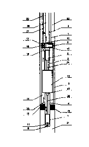
(54) English Title: OIL WELL PUMPING UNIT
(54) French Title: MODULE DE POMPAGE POUR PUITS DE PETROLE
Status: Deemed Abandoned and Beyond the Period of Reinstatement - Pending Response to Notice of Disregarded Communication
Bibliographic Data
(51) International Patent Classification (IPC):
  • F04B 47/12 (2006.01)
  • E21B 43/12 (2006.01)
  • F04B 47/00 (2006.01)
  • F04B 53/00 (2006.01)
(72) Inventors :
  • SIDOROV, DMITRIY (Russian Federation)
  • LAPSIN, ANDREY V. (Canada)
  • MINENKOV, VALERIY (Russian Federation)
(73) Owners :
  • ANDREY V. LAPSIN
  • VALERIY MINENKOV
(71) Applicants :
  • ANDREY V. LAPSIN (Canada)
  • VALERIY MINENKOV (Russian Federation)
(74) Agent: PERRY + CURRIER
(74) Associate agent:
(45) Issued:
(22) Filed Date: 2014-02-20
(41) Open to Public Inspection: 2015-08-20
Examination requested: 2020-02-19
Availability of licence: N/A
Dedicated to the Public: N/A
(25) Language of filing: English

Patent Cooperation Treaty (PCT): No

(30) Application Priority Data: None

Abstracts

English Abstract


An oil well pumping unit is provided. The oil well pumping unit includes lift
and
pump/compressor tubing columns, plunger pumps, a packer, and combined
assemblies
installed in upper and lower portions of a casing.


Claims

Note: Claims are shown in the official language in which they were submitted.

What is claimed is:
1. An oil well pumping unit designed for simultaneous dual production from two
formations
in a well, the unit comprising:
lift and pump/compressor tubing columns;
plunger pumps having suction and discharge valves located in a casing and a
linear
motor installed between said suction and discharge valves;
a packer having an annular space between the casing and the linear motor;
combined assemblies installed in upper and lower portions of the casing, the
upper
portion having built-in valves, an access port for directing the upward flow
of the oil
well fluid in the sub-packer zone from the annular space towards the lift
column,
and an opening for cable entry installation, the lower portion having a
pressure-
tight connection with the casing and the pump/compressor tubing column.
2. The oil well pumping unit of claim 1, further comprising a gland seal
installed between
the lower combination assembly and the jacket.
-4-

Description

Note: Descriptions are shown in the official language in which they were submitted.


CA 02843528 2014-02-20
OIL WELL PUMPING UNIT
FIELD
[0001] This design relates to the oil industry, in particular to machines
for oil production
equipped with oil well pumps.
BACKGROUND
[0002] An oil well pumping unit for simultaneous dual production from two
formations of a
well is known. It includes lift and pump/compressor tubing columns, plunger
pumps with suction
and discharge valves located in the casing, and a linear motor which is
installed between them
(FR2385911A, 27.10.1978).
[0003] The disadvantages of the currently known unit are its complex
design, the
impossibility of separating the flows of oil well fluid produced in sub-packer
and supra-packer
zones, as well as the impossibility of complying with the cooling mode of its
linear motor.
SUMMARY
[0004] The unit is designed for use in the oil industry for producing oil
by means of oil-well
pumps with simultaneous dual production from two formations of one well. The
unit is for
simultaneous dual production from two formations in a well includes lift and
pump/compressor
tubing columns and plunger pumps, suction and discharge valves located in the
casing. A liner
motor is installed between the pumps. The unit is fitted with a packer. An
annular space is
situated between the casing and the motor. Combined assemblies are installed
in the upper and
lower portions of the casing; the upper one includes built-in valves, an
access port for directing
the upward flow of oil well fluid in the sub-packer zone from the annular
space to the lift column,
and a port for cable entry installation. The lower assembly has a pressure-
tight connection with
the casing and pump/compressor tubing column. The design is simplified,
reliability is
increased, and the flow separation of oil well fluid from the sub-packer and
supra-packer zones
is ensured.
[0005] The objective put forward in the present invention is to simplify
the design, increase
its reliability, and simultaneously ensure the flow separation of oil well
fluid in the sub-packer
and supra-packer zones.
-1-

CA 02843528 2014-02-20
BRIEF DESCRIPTION OF THE DRAWING
[0006] Reference will now be made, by way of example only, to the
accompanying drawings
in which:
[0007] Figure 1 is a cross sectional view of a unit according to an
embodiment.
DETAILED DESCRIPTION OF THE EMBODIMENTS
[0008] The indicated objective and the technical result are achieved
because the oil well
pumping unit, which is designed for simultaneous dual production from two
formations in a well
and which includes lift and pump/compressor tubing columns, plunger pumps with
suction and
discharge valves located in the casing, and a linear motor installed between
them, is fitted with
a packer in accordance with the invention, and there is an annular space
between the casing
and the linear motor. At the same time combined assemblies are installed in
the upper and
lower portions of the casing; the upper one includes built-in valves, an
access port for directing
the upward flow of the oil well fluid in the sub-packer zone from the annular
space towards the
lift column, as well as an opening for cable entry installation, and the lower
one has a pressure-
tight connection with the casing and the pump/compressor tubing column.
[0009] A packing seal is installed between the lower combined assembly and
the casing.
[0010] Referring to Figure 1, the pumping unit for simultaneous dual
production from two
formations in a well includes lift 1,2 and pump/compressor 3,4 tubing columns
and upper
plunger pump 6 and lower plunger pump 7 located in casing 5, suction 8,9 and
discharge 10,11
valves. Linear motor 12 is installed between the pumps. The unit is fitted
with a packer 13. The
annular space 14 is situated between casing 5 and linear motor 12. The
combined assemblies
15 and 16 are installed in the upper and lower portions of casing 5. The upper
assembly 15
includes built-in suction 8 and discharge 10 valves. An access port 17 is
provided for directing
the upward flow of the oil well fluid in the sub-packer zone from the annular
space 14 to the lift
column. Also the assembly includes a cable entry 18 to connect the cable
extension 19 of the
motor with cable line 20.
[0011] The upper combined assembly 15 is designed for separating the flows
of oil well fluid
which are produced in sub-packer zone 21 and supra-packer zone 22. The lower
combined
assembly 16 has a pressure-tight connection with casing 5 and pump/compressor
tubing
column 4 and is fitted with access port 23.
-2-

CA 02843528 2014-02-20
[0012] The unit operates in a following manner.
[0013] The electrical power from the control station is supplied to the
linear motor 12 along
cable line 20 via cable entry 18 and by way of cable extension 19. Electrical
power is converted
by the linear motor 12 into mechanical energy in the form of reciprocal
movement of a rod,
which connects the motor with the pump plungers.
[0014] During the motor rod stroke the movement is transferred to the upper
plunger pump
6 via the upper shaft 24 and to the lower plunger pump 7 via lower shaft 25
and the line of rods
26, which by design are connected to the linear motor casing by the
pump/compressor tubing
columns 3 and 4. When the motor rod stroke moves downward, the lower plunger
pump 7
discharges oil well fluid via valve 11 and access port 23 into annular space
14, and upper
plunger pump 6 sucks oil well fluid via valve 8 from the casing annulus of
supra-packer zone 22.
At the same time valves 9 and 10 are closed. Oil well fluid from the lower
plunger pump 7, while
passing along annular space 14 via access port 16 enters annular space 27
between the lift
columns and then by way of the lift column of pump/compressor tubing column 1
it goes to the
wellhead.
[0015] During the rod stroke upper plunger pump 6 discharges oil well fluid
via valve 10 into
annular space 28 of lift column 2. And lower plunger pump 7 sucks oil well
fluid via valve 9 from
sub-packer zone 21. At the same time valves 8 and 11 are closed. From the
upper plunger
pump oil well fluid enters annular space 28, and then by way of the lift
column of
pump/compressor tubing column 2 it goes to the wellhead.
[0016] The unit as described can be used for the production of oil from
wells with casing
strings of a diameter not less than 168 mm and permits the development of two
production
horizons of one well at the same time using one linear motor.
[0017] While specific embodiments have been described and illustrated, such
embodiments
should be considered illustrative only and should not serve to limit the
accompanying claims.
-3-

Representative Drawing
A single figure which represents the drawing illustrating the invention.
Administrative Status

2024-08-01:As part of the Next Generation Patents (NGP) transition, the Canadian Patents Database (CPD) now contains a more detailed Event History, which replicates the Event Log of our new back-office solution.

Please note that "Inactive:" events refers to events no longer in use in our new back-office solution.

For a clearer understanding of the status of the application/patent presented on this page, the site Disclaimer , as well as the definitions for Patent , Event History , Maintenance Fee  and Payment History  should be consulted.

Event History

Description Date
Deemed Abandoned - Failure to Respond to Maintenance Fee Notice 2022-08-22
Application Not Reinstated by Deadline 2022-08-03
Inactive: Dead - No reply to s.86(2) Rules requisition 2022-08-03
Letter Sent 2022-02-21
Deemed Abandoned - Failure to Respond to an Examiner's Requisition 2021-08-03
Examiner's Report 2021-04-01
Inactive: Report - No QC 2021-03-29
Common Representative Appointed 2020-11-08
Inactive: Ack. of Reinst. (Due Care Not Required): Corr. Sent 2020-04-01
Letter Sent 2020-04-01
All Requirements for Examination Determined Compliant 2020-02-19
Reinstatement Request Received 2020-02-19
Reinstatement Requirements Deemed Compliant for All Abandonment Reasons 2020-02-19
Request for Examination Requirements Determined Compliant 2020-02-19
Request for Examination Received 2020-02-19
Common Representative Appointed 2019-10-30
Inactive: Abandon-RFE+Late fee unpaid-Correspondence sent 2019-02-20
Change of Address or Method of Correspondence Request Received 2018-05-31
Inactive: Cover page published 2015-08-31
Application Published (Open to Public Inspection) 2015-08-20
Inactive: IPC assigned 2014-04-02
Inactive: IPC assigned 2014-04-01
Inactive: First IPC assigned 2014-04-01
Inactive: IPC assigned 2014-04-01
Letter Sent 2014-03-07
Filing Requirements Determined Compliant 2014-03-07
Inactive: Filing certificate - No RFE (bilingual) 2014-03-07
Application Received - Regular National 2014-02-28
Small Entity Declaration Determined Compliant 2014-02-20
Inactive: Pre-classification 2014-02-20

Abandonment History

Abandonment Date Reason Reinstatement Date
2022-08-22
2021-08-03
2020-02-19

Maintenance Fee

The last payment was received on 2021-02-16

Note : If the full payment has not been received on or before the date indicated, a further fee may be required which may be one of the following

  • the reinstatement fee;
  • the late payment fee; or
  • additional fee to reverse deemed expiry.

Patent fees are adjusted on the 1st of January every year. The amounts above are the current amounts if received by December 31 of the current year.
Please refer to the CIPO Patent Fees web page to see all current fee amounts.

Fee History

Fee Type Anniversary Year Due Date Paid Date
Registration of a document 2014-02-20
Application fee - small 2014-02-20
MF (application, 2nd anniv.) - small 02 2016-02-22 2016-01-20
MF (application, 3rd anniv.) - small 03 2017-02-20 2017-02-08
MF (application, 4th anniv.) - small 04 2018-02-20 2018-02-09
MF (application, 5th anniv.) - small 05 2019-02-20 2019-02-20
MF (application, 6th anniv.) - small 06 2020-02-20 2020-02-19
2020-02-20 2020-02-19
Request for examination - small 2019-02-20 2020-02-19
MF (application, 7th anniv.) - small 07 2021-02-22 2021-02-16
Owners on Record

Note: Records showing the ownership history in alphabetical order.

Current Owners on Record
ANDREY V. LAPSIN
VALERIY MINENKOV
Past Owners on Record
DMITRIY SIDOROV
Past Owners that do not appear in the "Owners on Record" listing will appear in other documentation within the application.
Documents

To view selected files, please enter reCAPTCHA code :


To view images, click a link in the Document Description column. To download the documents, select one or more checkboxes in the first column and then click the "Download Selected in PDF format (Zip Archive)" or the "Download Selected as Single PDF" button.

List of published and non-published patent-specific documents on the CPD .

If you have any difficulty accessing content, you can call the Client Service Centre at 1-866-997-1936 or send them an e-mail at CIPO Client Service Centre.


Document
Description 
Date
(yyyy-mm-dd) 
Number of pages   Size of Image (KB) 
Abstract 2014-02-19 1 6
Description 2014-02-19 3 139
Claims 2014-02-19 1 21
Drawings 2014-02-19 1 25
Representative drawing 2015-07-22 1 14
Filing Certificate 2014-03-06 1 177
Courtesy - Certificate of registration (related document(s)) 2014-03-06 1 102
Reminder of maintenance fee due 2015-10-20 1 111
Reminder - Request for Examination 2018-10-22 1 118
Courtesy - Abandonment Letter (Request for Examination) 2019-04-02 1 168
Courtesy - Acknowledgment of Reinstatement (Request for Examination (Due Care not Required)) 2020-03-31 1 405
Courtesy - Acknowledgement of Request for Examination 2020-03-31 1 434
Courtesy - Abandonment Letter (R86(2)) 2021-09-27 1 550
Commissioner's Notice - Maintenance Fee for a Patent Application Not Paid 2022-04-03 1 551
Courtesy - Abandonment Letter (Maintenance Fee) 2022-09-19 1 549
Maintenance fee payment 2019-02-19 1 24
Reinstatement 2020-02-18 3 112
Maintenance fee payment 2020-02-18 1 25
Correspondence related to formalities 2020-11-03 3 149
Correspondence related to formalities 2020-12-31 3 145
Maintenance fee payment 2021-02-15 1 25
Correspondence related to formalities 2021-02-28 3 131
Examiner requisition 2021-03-31 5 218