Note: Descriptions are shown in the official language in which they were submitted.
CA 02843810 2014-01-31
WO 2013/024039 PCT/EP2012/065715
Method and System For Controlling Hydroelectric Turbines
Field of the Invention
This invention relates to a method and system for controlling turbines, and in
particular, a method and system
for providing control of hydroelectric turbines to optimise the performance of
the turbines.
Background of the Invention
Hydroelectric turbines are recognised as a means for effectively harnessing a
clean and renewable energy
source. Groups of hydroelectric turbines, installed in the sea, exploit
natural currents caused by tides or by
river flows near estuaries, to thereby generate electrical power for provision
to utility grids, generally provided
on shore.
Access to turbines installed in the sea is expensive and hazardous. Therefore,
it is preferable, where possible, to
avoid the use of components that present any risk of failure or wear. Thus,
fixed pitch turbine blades are
preferable to blades with adjustable pitch mechanisms, low-speed generators
coupled directly to the turbine are
preferable to high-speed generators coupled through gears and permanent-magnet
excitation of the generators
is preferred to arrangements that require brushes and slip rings or
commutators.
In most cases, the groups of turbines comprise large numbers of turbines.
Given the large number of turbines
involved, it would be impractical and uneconomic to deliver the power to shore
by a separate power cable
connected to each turbine. Therefore, each power cable installed for
transmitting power to shore is preferably
arranged to collect the power from several turbines. In order for a
significant amount of power to be
transmitted from the group of turbines to a grid connection point on shore,
which may be typically several
kilometers from the turbines, the power cable operates at a high voltage.
However, electrical elements within
the turbine, such as generator windings, are normally designed to operate at
much lower voltages for reliability
and economy.
Furthermore, turbulence, and irregular topography of the seabed and nearby
shorelines cause differences in the
water flow velocity, and therefore, differences in the available power at each
turbine within a group of turbines
served by a single cable. In order to obtain the maximum power from the water
current, a rotational speed of
each turbine of the group of turbines should be adjusted in accordance with
the prevailing water flow velocity.
Thus, the turbines within a group are typically operated at different speeds
and if fitted with permanent magnet
generators, produce electrical outputs of differing frequency and voltage.
It is therefore an object of the present invention to provide a system for
converting electrical power produced
by a turbine to a form compatible with a power transmission system for
transmitting the electrical power to
shore, whilst ensuring the performance of the turbine and of the group of
turbines as a whole, is optimised.
Summary of the Invention
According to the present invention there is provided a control system for
controlling an operation of a
hydroelectric turbine, the control system comprising:
CA 02843810 2014-01-31
WO 2013/024039 PCT/EP2012/065715
2
a converter system, arranged to convert AC power, supplied by a generator
connected to the turbine, and
having a voltage and frequency that is a function of a rotational speed of the
turbine, to AC power having a
voltage and frequency of a transmission system for transmitting the AC power
to a receiving station;
the system further comprising a control unit, the control unit being co-
operable with the converter system to
adjust the AC voltage supplied by the generator in response to a water flow
speed through the turbine to
thereby control rotation of the turbine.
Preferably, the AC power supplied by the generator has a voltage and frequency
that is proportional to the
rotational speed of the turbine.
Preferably, the converter system comprises a first-stage converter and a
second-stage converter, with a DC link
provided between the first and second-stage converters, the first-stage
converter being arranged to convert the
AC power supplied by the generator to DC power, and the second-stage converter
being arranged to convert
the DC power to the AC Power for transmission to the receiving station.
Alternatively, the converter system comprises a cycloconverter or a matrix
converter, arranged to convert the
AC supplied by the generator to the AC Power for transmission to the receiving
station.
Preferably, the DC link includes at least one sensor for sensing a DC current
and is arranged to provide signals
associated with the sensed DC current to the control unit.
Preferably, the DC link includes at least one sensor for sensing a DC voltage
and is arranged to provide signals
associated with the sensed DC voltage to the control unit.
Preferably, the first-stage converter comprises a rectifier.
Preferably, the rectifier is a three-phase, phase-controlled rectifier, and
the control unit is arranged to adjust a
delay angle of a thyristor trigger signal of the phase-controlled rectifier.
Alternatively, the first-stage converter comprises a thyristor AC controller
in series with a diode bridge.
Preferably, the second-stage converter is a phase-controlled, current-source,
line-commutated inverter.
Preferably, responsive to the water flow speed being less than a rated value,
the control unit is arranged to
adjust a firing angle of thyristors of the second-stage converter to set the
DC link voltage to a value for
providing an optimum DC power value at the DC link.
Preferably, responsive to the water flow speed being less than a threshold
value, the control unit is arranged to
set the first-stage converter to behave as an uncontrolled rectifier, to
determine the DC link current, to
determine an optimum DC power value associated the water flow speed for the
turbine, and to adjust the
CA 02843810 2014-01-31
WO 2013/024039 PCT/EP2012/065715
3
operation of the second-stage converter to set the DC link voltage to a value
to provide the optimum DC power
value for the determined DC link current.
Preferably, responsive to the water flow speed exceeding a rated value, the
control unit is arranged to adjust a
firing angle of thyristors of the second-stage converter to set the DC link
voltage to a threshold DC voltage
value, and to adjust a firing angle of thyristors of the first-stage converter
for setting the DC link current to the
fixed value for restricting the DC power to the optimum DC power value.
Preferably, responsive to the water flow speed exceeding a threshold value,
the control unit is arranged to
adjust the second-stage converter to set the DC link voltage to a threshold DC
voltage value, to determine an
optimum DC power value associated the water flow speed for the turbine, and to
adjust the first-stage
converter to set the DC link current to a fixed value to restrict the DC power
to the optimum DC power value.
Alternatively, the first stage converter and the second-stage converter are of
a voltage-source inverter type.
Preferably, the first-stage converter is a voltage-source inverter operated as
an active front end and is arranged
to operate with a fixed-voltage DC link.
Preferably, the first-stage converter and the second-stage converter are six-
device, three-phase bridges, each
device comprising a switch and free-wheel diode.
Preferably, the switches are selected from any of semiconductor switches, such
as Insulated-Gate Bipolar
Transistor, IGBT, switching devices, Integrated Gate Commutated Thyristors,
(IGCT) or Gate Turn Off (GTO)
thyristors.
Preferably, the switching devices are arranged to receive and operate in
accordance with signals received from
the control unit.
Preferably, a capacitor is connected in parallel with DC terminals of the
first and second-stage converters and
is arranged to maintain a substantially constant DC link voltage over a period
of a switching cycle of the
switches of the devices.
Preferably, the control unit is arranged to control the devices of the first-
stage converter to thereby control a
voltage provided at an AC input of the first-stage converter.
Preferably, the control unit is arranged to control the devices of the first-
stage converter to set an amplitude and
frequency of the voltage at the generator terminals and the corresponding real
and reactive power flows.
Preferably, the first-stage converter is controlled to provide to the
generator, an AC voltage that changes
according to the electrical frequency in such a way that the resulting AC
current is in phase with an electro-
magnetic force induced in the windings of the generator.
CA 02843810 2014-01-31
WO 2013/024039 PCT/EP2012/065715
4
Preferably, the control unit is arranged to control the AC output voltage of
the second stage converter by
controlling an amplitude and frequency of the AC output voltage by means of
switching signal transmitted to
the devices of the second stage converter.
Preferably, the control unit is arranged to modify an operation of the devices
of the first-stage controller to
adjust the frequency of the AC voltage at the input terminals of the first-
stage converter to control the rotation
of the turbine.
Preferably, responsive to the water flow speed being less than a threshold
value, the control unit is arranged to
determine the DC link current, to determine an optimum DC power value
associated the water flow speed for
the turbine, and to adjust the operation of the first stage converter by
modifying a switching sequence of the
devices to adjust the frequency of the AC voltage at the input terminals to a
value to provide the optimum DC
power value for the determined DC link current.
Preferably, responsive to the water flow speed exceeding a threshold value,
the control unit is arranged to
determine an optimum DC power value associated the water flow speed for the
turbine, and to adjust the
operation of the first stage converter by modifying a switching sequence of
the devices to adjust the frequency
of the AC voltage at the input terminals to a value to provide a fixed value
to restrict the DC power to the
optimum DC power value.
Preferably, the threshold value is a normal operating flow speed or rated
speed.
Preferably, the control system is arranged to cooperate with a supervisory
controller to determine the threshold
value for the turbine.
Preferably, the threshold value is based on any of a performance level of each
turbine within an array of
turbine systems, a pattern of water flow across an array of turbines, and grid
operator preferences.
Preferably, each turbine system is connected to a common cable to shore.
Preferably, the performance level of the turbine includes an output power of
each turbine of the turbine
systems within the array of turbines.
Preferably, there is further provided a turbine system, the turbine system
comprising the converter system and
further comprising a hydroelectric turbine connected to a generator, the
generator being arranged to provide an
AC power output as an input to the control system.
Preferably, the turbine has fixed blades and the generator incorporates a
directly coupled permanent-magnet
generator.
CA 02843810 2014-01-31
WO 2013/024039 PCT/EP2012/065715
Preferably, the turbine system further comprises a transmission system,
including a transformer, the
transmission system being arranged to receive AC power output from the control
system and transmit the AC
power to a receiving station provided on shore.
5 Preferably, the turbine system further comprises a first power factor
correction component provided between
an output of the generator and an input of the converter system, to compensate
for effects of the converter
system on the generator's power factor.
Preferably, the first power correction component comprises three component
sets, each comprising an inductor
in series with a capacitor and each component set being provided in parallel
with respective three phase outputs
of the generator. The capacitors serve to reduce both the time harmonic
components of the generator current
and the reactive part of the fundamental component so that the generator
losses are reduced and each of the
inductors serve to prevent large current flowing through the corresponding
capacitors when the three-phase,
phase-controlled rectifier commutates.
Preferably, the turbine system further comprises a second power factor
correction component provided
between an output of the converter system and the transmission system to
ensure the transmission system
operates at a relatively high power factor. In this way, losses within the
cable to shore are minimised and the
transmission system operates at maximum capacity for delivering real power to
the grid.
Preferably, the second power factor correction component comprises three
component sets, each comprising at
least a capacitor, and optionally, an inductor in series with the capacitor,
and each component set being
provided in parallel with respective three phase outputs of the converter
system. The capacitors serve to reduce
the current carried by the transmission system in order to minimise losses and
to maximise the capacity of the
transmission system to transmit useful real power to shore and the inductors
are provided to prevent large
currents being drawn from the capacitors when the thyristors of the second-
stage converter are switched.
The capacitors may be connected to the high voltage terminals of the
transformer, or to the low voltage
terminals.
Alternatively, the second power factor correction component may be connected
to a separate winding of the
transformer so that a leakage inductance of the winding prevents the
capacitors from disrupting the operation
of the converter system.
Preferably, the turbine system, is provided with a first power cable arranged
to connect the turbine system to at
least one other turbine system in parallel, and is arranged to feed a common
second power cable which carries
the AC power to shore.
Alternatively, the second power factor correction components may be connected
to a junction between the first
and second power cables.
CA 02843810 2014-01-31
WO 2013/024039 PCT/EP2012/065715
6
The present invention further provides an array of turbine systems comprising
a plurality of turbine systems
connected together in parallel by a first power cable, the turbine systems
being arranged to feed a common
second power cable, which is arranged to carry the AC power to the receiving
station.
Preferably the array of turbine systems further comprises a supervisory
controller arranged to determine a
performance level of each turbine within the array and to instruct the control
unit of each turbine system to
adjust the AC voltage supplied by the generator to alter the power generated
by each turbine system to thereby
control the overall power generated by the array.
In this way, the output power of the array of turbine system can be monitored
and individual turbine systems
selected, such as those having turbines subjected to higher than average water
flows, and their operation
modified to compensate for other turbine systems within the array which are
not producing the rated power
because the associated water flow is lower than average.
Preferably, the first and second power cables are arranged to carry three-
phase AC current at a line-to-line
voltage suitable for electrical equipment that does not require oil
insulation, such as a line-to-line voltage of
22kV.
Brief Description of the Drawings
Embodiments of the invention will now be described, by way of example, with
reference to the accompanying
drawings, in which:
Fig. 1 is an electrical arrangement of a group of turbines systems, according
to a preferred embodiment of the
present invention;
Fig. 2 is a graphical representation of turbine characteristics as power
versus rotational speed;
Fig. 3 depicts one of the turbine systems of Fig. 1, including a power
converter system according to a first
embodiment of the present invention;
Fig. 4 depicts one of the turbine systems of Fig. 1, including a power
converter system according to a second
embodiment of the present invention;
Fig. 5 depicts one of the turbine systems of Fig. 1, including a power
converter system according to a third
embodiment of the present invention;
Fig. 6 depicts one of the turbine systems of Fig. 1, including a power
converter system according to a fourth
embodiment of the present invention;
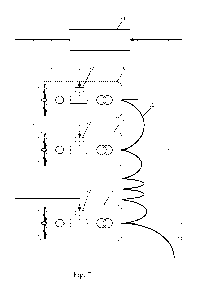
Fig. 7 depicts a supervisory controller arranged to communicate and cooperate
with a control unit of any of the
turbine systems of Fig. 3 to Fig. 6;
CA 02843810 2014-01-31
WO 2013/024039 PCT/EP2012/065715
7
Fig. 8 depicts the turbine system of Fig. 3, further including a first and
second power factor correction
component;
Fig. 9 depicts an alternative arrangement of the second power factor
correction component of Fig. 8;
Fig. 10 shows a relationship between characteristics including speed, torque
and power, of a turbine connected
to a control system of the present invention and water flow speed;
Fig. 11 shows a comparison of a variation in the turbine axial thrust and the
bending moment on turbine blades
as the rate of water flow increases, for a known turbine system, and a turbine
system of the present invention;
Fig. 12 depicts the regulation of the DC power in response to the water flow
speed, in accordance with a
preferred embodiment; and
Fig. 13 depicts an operation of the thyristors of the rectifier of the first-
stage converter and the inverters of the
second-stage converter, under the control of the control unit, according to a
preferred embodiment of the
present invention.
Detailed Description of the Invention
Referring to Fig. 1, there is illustrated a preferred electrical arrangement
of a group of turbine systems 10, and
preferably, hydroelectric turbines.
The turbine systems 10 are electrically connected together in parallel by a
short power cable 12, and feed one
or more main transmission power cable(s) 14 arranged to transmit power
collected from the group of turbine
systems 10 to a receiving station (not shown) provided near to or on shore. In
the preferred embodiment, the
power cables carry three-phase AC current at a line-to-line voltage of 22kV,
to thereby minimise any power
loss in the cable. However, it will be appreciated that any suitable cables
may be employed.
As illustrated, each turbine system 10 comprises a turbine 16, for example, a
tidal-current turbine. In the
preferred embodiment, the turbine preferably includes fixed blades.
The turbine 16 is connected to a generator 18, arranged to convert mechanical
energy generated by the turbine
16 to electrical energy. In the preferred embodiment, the generator 18 is a
directly coupled permanent-magnet
generator and provides a three-phase AC power output, having a voltage and
frequency that is proportional to a
rotational speed of the turbine 16. In an alternative embodiment, the
generator 18 is an induction generator
providing a three-phase AC power output, having a voltage and frequency that
is a function of a rotational
speed of the turbine 16. However, it will be appreciated that arrangements
with any suitable numbers of phases
may be employed. In some designs of generators, it is possible to separate
coils of the windings into groups to
provide two or more outputs that are electrically isolated.
CA 02843810 2014-01-31
WO 2013/024039 PCT/EP2012/065715
8
The output (or each electrical output, as the case may be) of the generator 18
is provided to AC terminals of a
power converter system 20 to convert the three-phase AC power to AC power in a
form compatible with a
transmission system 22 for transmitting power collected from the group of
turbine systems 10 to the receiving
station on shore.
The transmission system 22 includes a transformer 24 to increase the voltage
of the power delivered by the
converter system, typically 400 or 690V to the voltage of the transmission
system.
A transformer (not shown) provided at the receiving station (not shown) is
arranged to convert the power
received via the power cable 14 to a voltage suitable for connection to a grid
or alternatively, to a voltage
suitable for connection to a subsequent stage of power conversion that may be
needed prior to grid connection.
The voltage of 22kV is chosen because it is within the range of maintenance-
free cast-resin transformers. Such
transformers would be suitable for use within gas-filled enclosures located
close to the turbines 16. Higher
voltages may require an oil-filled transformer, which imposes a periodic
maintenance requirement and presents
a potential environmental hazard.
Tidal currents are generally turbulent causing the water flow speeds to
typically vary between 60% and 140%
of an average value, over time periods ranging from a few seconds to several
minutes. The power available
from the water flow is proportional to the cube of the flow speed and for a
typical case of a turbine having a
nominal rated power value of 1MW, when the average flow speed is 3m/s, the
available power from each
turbine may vary between 0.216MW and 2.744MW.
As depicted in the graph of Fig. 2, a relationship exists between electrical
power produced by a turbine and a
speed of rotation of the turbine, for a rated water flow speed. As
illustrated, the power generated for the
considered turbine increases as the speed of the rotation increases up to a
maximum power value of
approximately 1000kW for a rotational speed of between 20 and 25rpm.
Thereafter, the power generated
decreases as the speed of the rotation increases, depicting a zero power value
for rotational speed of between
and 40 rpm. Thus, it can be inferred that for a rated water flow value, the
power generated by a turbine
30 increases as the rotational speed of the blades of the turbine
increases. However, beyond a given threshold
value of speed of rotation, the generated power begins to decrease.
A ratio between mechanical power developed by the turbine 16 and power carried
by the water flow is called
the power coefficient (CP) of the turbine 16. The power carried by the water
flow is related to an area of the
35 turbine 16 intercepting the water flow and the speed of the water flow.
The power coefficient is a
dimensionless parameter that is a function of a tip speed ratio, which is a
second dimensionless parameter
equal to a ratio between peripheral speed of the turbine 16 and the speed of
the water flow. The power
coefficient reaches a maximum value for an optimum value of the tip speed
ratio. For the situation depicted in
Fig. 2, the tip speed ratio is equal to its optimum value when the rotational
speed is 22rpm and the maximum
power coefficient multiplied by the power of the flow yields a mechanical
power of 1MW.
CA 02843810 2014-01-31
WO 2013/024039 PCT/EP2012/065715
9
At times when the water flow speed is less than a normal operating flow speed,
or rated speed, it is desirable
that the torque or rotational speed of the turbine 16 is adjusted so that it
is being operated to extract as much
power from the water flow as possible. Similarly, at times when the water flow
speed exceeds the rated speed,
it is desirable to limit the power generated to a rated value to protect the
turbines 16 from excessive mechanical
stress and avoid overloading and overheating of other components within the
turbine system 10.
The power converter system 20 of the present invention is therefore arranged
to control the operation of the
turbines, and in particular, the rotational speed of the turbines, to ensure
optimal power is generated at times
when the water flow speed is less than a rated value, and limit the power
generated at times when the water
flow speed is greater than a rated value.
Accordingly, the power converter system 20 of the turbine system 10 is
preferably arranged to communicate
with a control unit 32. The control unit 32 is arranged to determine an
indication of the water flow speed
through the turbine 16. In the preferred embodiment, the present water flow
speed is inferred from the
measured current from the generator together with the operating frequency and
voltage. However, it will be
appreciated that the present water flow speed may be a measured value obtained
by a flow sensor or it may be
probabilistically derived using statistics and/or forecast information, for
example, or alternatively, by adjusting
a measured value of the water flow speed in accordance with information
derived from statistics and/or
forecasts.
Referring now to Fig. 3, there is illustrated the turbine system 10, including
a detailed depiction of the power
converter system 20 according to a first embodiment of the present invention.
In this first embodiment, the
power converter system 20 comprises a first-stage converter 26 and a second-
stage converter 28.
The first-stage converter 26 is a rectifier arranged to convert input AC power
received from the generator, and
having a frequency corresponding to a rotational speed of the generator, to DC
power. As illustrated, the
rectifier is preferably a three-phase, phase-controlled rectifier, such as a
thyristor bridge. Alternatively, it will
be appreciated that the first-stage converter 26 may be realised as a
thyristor AC controller, followed by a
diode bridge, as discussed in more detail below with respect to Fig. 4.
The second-stage converter 28 is an inverter arranged to convert the DC power
provided by the first-stage
converter 26 to AC power, having a voltage and frequency of the transmission
system 22. In this embodiment,
the inverter is a thyristor bridge operating as a phase-controlled, current-
source, line-commutated inverter.
For every value of the water flow speed, there is an optimum rotational speed
of the turbine 16 that yields
maximum output power from the turbine 16 and there is a corresponding optimum
relationship between the
voltage and current of a DC link 34, provided between first-stage converter 26
and the second-stage converter
28.
Thus, the control unit 32 is arranged to adjust the DC link voltage in
response to the present water flow speed,
in order to control the rotation of the turbine 16.
CA 02843810 2014-01-31
WO 2013/024039 PCT/EP2012/065715
When the water flow speed through the turbine 16 is less than the rated speed
value, the control unit 32 is
arranged to cause the first-stage converter 26 to operate or behave as an
uncontrolled rectifier (i.e., one in
which the firing angles are set to 0 degrees), such that the speed of the
generator 18 and the speed of the
5 turbine 16 are directly related to the voltage of the DC link 34. Thus,
by adjusting the DC link voltage to a set
value, the DC current is subsequently altered, and therefore the AC power,
enabling the control of the
rotational speed of the turbine 16, and in this case, preferably, causing a
reduction in the rotation of the turbine,
and thereby ensuring the optimum power is being extracted from the turbine.
10 The first-stage converter 26, and in the preferred embodiment, the
controlled rectifier, is used during periods of
high water flow speed to allow the rotational speed of the turbines 16 to rise
so that the generated power is
restricted to a desired maximum value.
When the water flow speed through the turbine 16 exceeds the rated speed
value, the control unit 32 is
arranged to set the second-stage converter 28, and in particular, the firing
or phase angle of the thyristors of the
second-stage converter 28, to provide a maximum value for the DC link voltage.
The control unit 32 is further
arranged to set the DC link current to a fixed value by adjusting the first-
stage converter 26, to thereby restrict
the power being yielded from the generator 18 to the desired maximum value.
Thus, the voltage at the input of
the first-stage converter 26 is increased, and accordingly, the rotational
speed of the turbine 16 is increased.
As illustrated in Fig. 3, an inductor 30 is preferably provided in series
between the output of the first-stage
converter and an input of the second-stage converter to handle varying demands
on the system, and to ensure
that the DC current remains continuous despite the switching of the
thyristors.
Due to the resulting high voltage produced by the generator 18, the first-
stage converter utilises switching
devices such as thyristors of very high rated voltage.
In a second embodiment, as illustrated in Fig. 4, instead of using very high
voltage thyristors, the voltage of
each of the three phase AC outputs from the generator 18 may be reduced by
connecting each output to an
inductive load 136, 236 and 336, provided in parallel with respective inputs
of the rectifier of the first-stage
converter 26. A reactive current drawn by the inductive load 136, 236 and 336
is arranged to cause a large
voltage drop in the winding inductance of the generator 18. The inductive
loads 136, 236 and 336 are
preferably connected to the rectifier of the first-stage converter by
respective solid-state switches 138, 238 and
338 and the rectifier is preferably a plain diode rectifier 40. In this
embodiment, the control unit 32 is arranged
to adjust the firing angle of the thyristors of the solid-state switch under
phase control in order to control the
first-stage converter, and therefore the rotation of the turbines 16.
In a third embodiment depicted in Fig. 5, two three-phase AC power outputs are
provided by the generator 18
and are arranged to feed into separate first and second power converter
systems 120 and 220, respectively. The
outputs of the first and second power converter systems 120 and 220 are
arranged to feed separate windings of
a common transformer creating a twelve-pulse system which produces
significantly lower harmonic current in
CA 02843810 2014-01-31
WO 2013/024039 PCT/EP2012/065715
11
the transmission system 22, than would be produced by a lower value pulse
system. It will be further
appreciated that the turbine system 10 of the present invention may employ any
number of suitable three-phase
groups.
It will be further appreciated that in the event of a fault occurring in one
of the two or more power converter
systems 120, 220, the other power converter system(s) could continue to
function and allow the turbine 10 to
operate with restricted maximum power. In such a case, the control units 32,
32' are preferably provided with a
detecting means (not shown) for detecting the fault and applying a suitably
reduced maximum power limit. It
will be that the control units 32, 32' are connected or otherwise arranged
such that they are capable of
communicating with one another. Alternatively, a single control unit 32 may be
employed and connected to
each of the power converter systems 120, 220.
In a fourth embodiment of the present invention, the power converter system 20
of Fig. 3 is replaced with the
power converter system 20 of Fig. 6. As illustrated, the power converter
system of Fig. 6 also comprises a first-
stage converter 26 and a second-stage converter 28. The first-stage converter
26 is arranged to convert AC
power supplied by the generator 18 to DC power, and the second-stage converter
28 is arranged to convert the
DC power to AC power for transmission to the receiving station (not shown).
As with the converter systems of the previous embodiments, the converter
system 20 of Fig. 6 is arranged to
communicate with a control unit 32 to receive control signals and to provide
the control unit 32 with a measure
of power passing through the power converter system 20. To this end, a sensor
(not shown) is provided at the
DC link 34 to detect and monitor the DC current passing between the first and
second-stage converters and to
transmit a signal to the control unit 32.
In this embodiment, the first-stage converter 26 and the second-stage
converter 28 are of a voltage-source
inverter type. In particular, the first-stage converter is preferably a
voltage-source inverter operated as an active
front end and is arranged to operate with a fixed-voltage DC link.
As illustrated in Fig. 6, the first-stage converter 26 and the second-stage
converter 28 are six-device, three-
phase bridges, each device 39 comprising a semiconductor switch and free-wheel
diode.
In this embodiment, the first-stage converter 26 and the second-stage
converter 28 are based on Insulated-Gate
Bipolar Transistor, (IGBT) switching devices 39. However, it will be
appreciated that other types of switching
such as Integrated Gate Commutated Thyristors, (IGCT) or Gate Turn Off (GTO)
thyristors may be employed.
The switching devices 39 are controlled and operate in accordance with signal
received from the control unit
32.
As illustrated in Fig. 6, a capacitor 41 is preferably connected in parallel
with DC terminals of the first and
second-stage converters 26 and 28. The capacitor 41 is arranged to maintain a
substantially constant DC link
voltage over a period of a switching cycle of the switching devices 39. The
control unit 32 is arranged to
CA 02843810 2014-01-31
WO 2013/024039 PCT/EP2012/065715
12
adjust a phase of output voltage of the second-stage converter 28 in response
to changes in the voltage at the
capacitor 41, thereby maintaining the DC link voltage within close limits of a
specified value.
In this embodiment of the invention, the second-stage converter 28 is arranged
to convert the DC power
provided by the first-stage converter to AC power for transmission to the
receiving station (not shown). A
voltage provided at an AC output terminal comprising output AC lines, A, B and
C, of the second-stage
converter 28 is preferably achieved using pulse width modulation, (PWM).
In order to control the voltage provided at line A, a switch Si of the second-
stage converter 28 is repeatedly
switched on and off. When switch Si is on, current flows from a positive DC
line to line A. When switch Si is
off, the current continues to flow in the same direction through the line A
because of inductance in components
within the transmission system such as the transformer and is forced to pass
through a free-wheel diode D2
provided in parallel with a second switch S2. When current is flowing in the
other direction, it passes through
switch S2 and free-wheel diode D1 provided in parallel with the first switch
Si.
When switch Si is on, the voltage at line A is substantially equal to a
voltage of the positive DC line and when
switch Si is off, the voltage at line A is substantially equal to a voltage of
a negative DC line. A time average
voltage at line A is therefore related to the voltage at the positive and
negative DC lines and a ratio of a
duration of switch Si being on to the duration of off periods. Thus, an
average voltage at line A can be
controlled by controlling switching signals sent to switches Si and S2.
In particular, by varying the switching ratio of on to off periods at the
switches Si and S2 of the devices 39, the
average voltage at the line A can be controlled to take any value between the
voltages at the two DC lines.
Thus, in this embodiment, the control unit 32 provides a high frequency
switching signal with the ratio varying
cyclically to create an approximately sinusoidal voltage with superimposed
high frequency component at line
A of the AC output terminal. Preferably, a small filter (not shown) is
employed to attenuate the high frequency
component.
The voltage at lines B and C is controlled in the same manner by controlling
the devices 39 associated with
lines B and C.
For example, the DC link 34 may operate at 1100V and the switching signal fed
to the gates of the IGBTs of
the second-stage converter 28 may have a frequency of typically 3000Hz. The
ratio of on to off periods may be
varied between 1:10 and 10:1 so that an average voltage at the AC output
terminal varies between 100 and
1000V. If the ratio varies sinusoidally in time with a frequency of 50Hz, then
the output voltage at line A of
the AC output terminal has an average value of 550V with a superimposed 50Hz
AC component with
amplitude 450V and rms value 318V.
A similar signal fed to the switches S3 and S4, connected to line B causes the
voltage at line B to vary in the
same way but it may be phase shifted so that the 50Hz component is 120 degrees
out of phase with that on line
A. An AC voltage between lines A and B is therefore 551V rms and if the signal
fed to the switches S5 and S6
CA 02843810 2014-01-31
WO 2013/024039 PCT/EP2012/065715
13
for line C is further phase shifted by 120 degrees then the three lines A, B
and C, carry a balanced three-phase
output voltage of 551 Vrms Line to Line. By suitably changing the switching
signals, the control unit 32 can
control the AC output voltage in amplitude and frequency.
The amplitude of the output AC voltage of the second-stage converter 28
determines an amount of reactive
power that flows into the three-phase AC network and the phase of the output
voltage with respect to the
network voltage determines the real power flow.
Similarly, the control unit 32 is arranged to control the devices 39 of the
first-stage converter 26 to thereby
control a voltage provided at an AC input of the first-stage converter 26, and
therefore an AC voltage at the
terminals of the generator 18. In particular, the first-stage converter 26 is
controlled to set the amplitude and
frequency of the voltage at the generator terminals and the corresponding real
and reactive power flows.
Furthermore, the first-stage converter 26 is controlled to provide to the
generator 18, an AC voltage that
changes according to the electrical frequency in such a way that the resulting
AC current is in phase with an
electro-magnetic force (emf) induced in the windings of the generator 18.
For a given water flow speed, the turbine 16 is associated with a
substantially ideal rotational speed, a resulting
frequency and emf and a corresponding power. Therefore, for the substantially
ideal rotational speed, a
component of the generator AC current, in phase with the emf, is a known
function of frequency. A maximum
efficiency of the generator is obtained when loss and therefore current, is
minimised, which, in turn, means that
the component of current in phase quadrature with the emf is preferably zero.
The corresponding AC voltage at
the generator terminals can be evaluated as a function of frequency and can be
fixed as a demand parameter for
the control unit 32.
As previously discussed, for every value of the water flow speed, there is an
optimum rotational speed of the
turbine 16 that yields maximum output power from the turbine 16 and there is a
corresponding optimum
relationship between frequency, voltage and power. The AC power is directly
proportional to the DC link
current since the DC link voltage is fixed. The control unit 32 is therefore
arranged to set the frequency of the
first stage converter according to the DC link current as measured by the
sensor (not shown), in order to
control the AC voltage at the generator.
In particular, the control unit 32 is arranged to modify an operation of the
devices 39 of the first-stage
controller 26 to adjust the frequency of the AC voltage at the input terminals
of the first-stage converter in
response to the present value of the DC link current.
When the water flow speed through the turbine 16 is less than the rated speed
value, the control unit 32 is
arranged to cause the first-stage converter 26 to adjust a frequency of the AC
voltage at the input terminals of
the first-stage converter, and therefore the AC terminals of the generator 18,
so that the rotational speed of the
generator and the turbine is optimised to extract the maximum power from the
flow.
CA 02843810 2014-01-31
WO 2013/024039 PCT/EP2012/065715
14
The first-stage converter 26 is used during periods of high water flow speed
to allow the rotational speed of the
turbines 16 to rise so that the generated power is restricted to a desired
maximum value. When the water flow
speed through the turbine 16 exceeds the rated speed value, the control unit
32 is arranged to cause the first-
stage converter 26 to adjust a frequency of the AC voltage at the input
terminals of the first-stage converter,
and therefore the AC terminals of the generator 18, so that the rotational
speed of the generator 18 and the
turbine 16 results in the power being limited to a maximum value. If the flow
is very high, the corresponding
ideal voltage will exceed the voltage rating of the first stage converter 26
and the generator 18 will be required
to carry a certain amount of AC current in phase quadrature with the emf and
the loss in the generator 18 will
be correspondingly higher than the minimum.
It will be appreciated that similar to the embodiment depicted in Fig. 5, the
turbine system 10 of Fig. 6 may be
modified to comprise two or more power conversion systems 20, each having
parallel power conversion
channels with separate DC links. This provides redundancy so that in the event
of a failure of one of the
channels, the turbine 16 may continue operating with restricted maximum power.
The separate channels each
take input from isolated sections of the generator winding so that a fault in
one channel does not affect the
operation of the others.
As previously discussed, a power cable 14 installed for transmitting power to
shore is preferably arranged to
collect the power from several turbine systems 10 in an array of turbine
systems. The power cable to shore 14
and other infrastructure used to deliver power to the grid onshore represent a
very large investment and it is
preferable to utilise it to the maximum possible at all times. Therefore, when
some of the turbines 16 in the
array are operating at less than P/N where P is the maximum capacity of the
cable and N is the number of
turbines, it is useful to allow the other turbines to deliver more than P/N to
thereby balance the overall amount
of power being delivered. At other times it may be desirable or necessary to
reduce the power generated, for
example if the utility grid is lightly loaded and the grid operator requests a
power contribution from the array
of turbines that is lower than the power available from the prevailing flow.
The present invention therefore further provides a means for adjusting and
controlling the maximum power
limit of individual turbines 16 according to the prevailing flow velocities at
the other turbines, and the power
being extracted by the other turbine systems 10 in the array. To this end, in
the preferred embodiment, the
control unit 32 is arranged to communicate and cooperate with a supervisory
controller 54, as illustrated in Fig.
7, that acts to optimise the operation of an array or group of turbines 16 as
a whole. The supervisory controller
54 is preferably arranged to monitor performance levels, including the output
power of each turbine 16 within
the array or group of turbines and is arranged to compensate for turbines 16
which are not producing the rated
power because the associated water flow is lower than average, by instructing
the control units 32 of turbine
systems 10 whose turbines 16 are being subjected to higher flows to yield
higher than rated power.
In the case that a total power generated by the array of turbines as a whole
exceeds a threshold such as a
threshold limit imposed by a grid operator, the supervisory controller 54 is
arranged to direct the control unit
32 of some or all of the turbine systems 10 in the array to reduce the fixed
value of the DC link current to
thereby restrict the total output power yielded. Similarly, in the case that
other turbines 16 in the array of
CA 02843810 2014-01-31
WO 2013/024039 PCT/EP2012/065715
turbine systems 10 are being subjected to a lower than average water flow, and
are therefore are not producing
the rated power, the supervisory controller 54 is arranged to direct or
instruct the control unit 32 of selected
turbine systems within the array to increase the fixed value of the DC link
current to yield higher than rated
power outputs and to thereby compensate for the lower power output being
yielded by the other turbines 16 in
5 the array.
Higher than rated power can be extracted by the turbine systems 10 at higher
water flows in proportion to the
square of the water flow by employing power factor correction components
between the generator 18 and the
power conversion system 20, as is explained in more detail below.
Power converter systems using phase-controlled rectifiers cause generators to
operate at a power factor
significantly less than unity. Thus, the generators are required to have a
generator rating larger than otherwise
necessary, which involves an increased quantity of magnetic material, and
therefore increased cost.
Thus, in a preferred embodiment of the present invention, in order to
compensate for the effect of the power
converter system 20 on the generator's power factor, a first power factor
correction component 42 is provided
between the output of the generator 18 and the input of the first-stage
converter of the power converter system
of the turbine system of Fig. 3, as illustrated in Fig. 8.
20 In a preferred embodiment, the first power factor correction component
42 comprises three component sets
142, 242 and 342, respectively, each comprising an inductor 144, 244, 344, in
series with a capacitor 146, 246,
346, and each component set 142, 242 and 342, being in parallel with
respective three phase outputs of the
generator 18. Each of the capacitor 146, 246, 346, reduces both the time
harmonic components of the generator
current and the reactive part of the fundamental component so that the
generator losses are reduced. Each of
the inductors 144, 244, 344, serves to prevent large current flowing through
the corresponding capacitors 146,
246, 346, when the three-phase, phase-controlled rectifier 26 commutates.
In order to minimise losses and to maximise the capacity of the transmission
system 22 to transmit useful real
power to shore, a second power factor correction component 48 is provided
between the output of the second-
stage converter of the power converter system 20 and the transmission system
of the turbine system of Fig. 3,
as illustrated in Fig. 8.
In the preferred embodiment, the second power factor correction component 48
comprises three component
sets 148, 248 and 348, respectively, each comprising an inductor 150, 250, 350
in series with a capacitor 152,
252, 352, and each component set 144, 244 and 344, being in parallel with
respective three phase outputs of the
second-stage converter 28. Each of the capacitors 152, 252, 352 reduce the
current carried by the transmission
system 22 in order to minimise losses and to maximise the capacity of the
transmission system 22 to transmit
useful real power to shore. The inductors 150, 250, 350 are provided to
prevent large currents being drawn
from the capacitors 152, 252, 352, when the thyristors of the second-stage
converter 28 are switched.
CA 02843810 2014-01-31
WO 2013/024039 PCT/EP2012/065715
16
However, it will be appreciated that instead, the second power factor
correction component 48 may be
connected to a separate winding of the transformer 24, as illustrated in Fig.
9. In this case the leakage
reactance of the transformer is normally sufficient to limit the current in
the capacitor during commutation of
the second-stage converter and the series inductors may be unnecessary.
Although the example of the power converter system 20 of Fig. 3 was employed
in order to described the
application of power correction components it will be appreciated that any of
the power conversion
embodiments disclosed could be modified to include power factor correction
components described in order to
compensate for the effect of the power converter system 20 on the generator's
power factor and to minimise
losses and to maximise the capacity of the transmission system 22 to transmit
useful real power to shore.
Fig. 10 shows a relationship between characteristics including speed, torque
and power, of a turbine connected
to a control system of the present invention, which employs a power cap or
limitation on the power produced
for water flow speed beyond a threshold value, and water flow speed. As
depicted, as the water flow speed
increases towards the rated water flow speed, the speed, torque and power of
the turbine increase. However,
once the water flow speed exceeds the rated value, the power is capped, and
the torque levels off, and tends to
decrease as the water flow speed continues to increase. The speed of the
turbines is increased to prevent
excessive mechanical stress being placed on the turbine. Clearly, the control
unit may be used to limit the
torque at the onset of the power limit. This offers a reduction in the
mechanical loads on the machine. In
particular, Fig. 10 shows that for the particular example depicted, over a
small range of flow between about 3.5
and 4.2 m/s the torque has been further restricted to a maximum value of about
300 kN.m. In the case that the
power converter system employed is a voltage controlled inverter system such
as the embodiment of Fig. 6,
this is achieved by restricting the power using frequency control.
Alternatively, in the case that the power
converter system employed is a current controlled inverter system such as the
embodiment of Fig. 3, such as a
phase-controlled thyristor bridge, then the torque may be restricted by means
of adjusting the trigger delay
angle as illustrated in Figure 13 and discussed in more detail below.
Fig. 11 shows the variation in the turbine axial thrust and the bending moment
on the turbine blades, as the rate
of water flow increases. It can be seen that values for the blade bending
moment and total thrust of the blades
of the turbine are controlled to a reduced value by virtue of the control
system of the present invention.
However, the values for the blade bending moment and total thrust of the
blades of the turbine, when the
turbine has a maximum power coefficient (CP), and is not being controlled by
the control system of the present
invention, are shown to steadily increase as the rate of water flow increases.
Preferably, the maximum torque
value is a predetermined value and is selected to ensure that the temperature
of the generator windings does not
exceed a safe value. Furthermore, the maximum torque value is preferably
chosen also to limit the stresses
within the turbine 16 to an acceptable level because the torque and the
stresses are related. Figure 11 shows
the relationship between two of the critical mechanical loads, the bending
moment in the blades and the total
axial thrust on the turbine. It can be seen that limiting the power when the
speed of the flow is high leads to
corresponding reductions in the mechanical loads and consequent reduction in
stress. Figure 11 corresponds to
the case where the power has been restricted to a fixed value but it would be
equally possible to further restrict
the power and so limit the corresponding mechanical loads and stresses.
CA 02843810 2014-01-31
WO 2013/024039 PCT/EP2012/065715
17
Fig. 12 depicts the regulation of the DC power in response to the water flow
speed as described above, and Fig.
13 depicts the operation of the thyristors of the rectifier of the first-stage
converter 26 and the inverters of the
second-stage converter 28, under the control of the control unit 32. As
illustrated in Fig. 13, for the turbine
being considered, the rated water flow speed is approximately 4.1m/s, and
therefore, for a water flow speed
increasing up to the rated water speed value, the graph depicts the firing
angle of the thyristors of the second-
stage converter being activated at increasingly greater angles. Once the water
flow speed exceeds the rated
water flow value, the thyristors of the first-stage converter are fired at
increasingly greater angles in accordance
with the increasing water flow speed, but the thyristors of the second-stage
converter are held at a constant
firing angle to ensure the maximum DC link voltage is provided.
The invention is not limited to the embodiment(s) described herein but can be
amended or modified without
departing from the scope of the present invention.