Note: Descriptions are shown in the official language in which they were submitted.
CA 02844022 2014-02-03
WO 2013/021186 PCT/GB2012/051900
- 1 -
Dual Chamber Device
The present invention is directed to a dual chamber device
for sequentially dispensing two compositions, without the
compositions mixing with each other.
In some situations it may be necessary or desirable to
dispense two compositions which are not mixed with one
another but are delivered directly one after the other. One
example is in veterinary medicine for treating infection in
the udder of animals such as cattle. It is desirable to
first inject an antibiotic composition to treat the
infection and then to deliver a teat seal to seal the teat
canal to prevent the entry of further bacteria.
Various devices and syringes with two or more chambers are
known. Many are used where two compositions must be mixed
together before they are delivered. Some designs employ
separate barrels either adjacent to one another, or a first
cylindrical barrel surrounded by an annular second barrel,
with each barrel having a separate plunger. Examples can be
found in WO 2007/006030 and US 2004/092864. Other designs
include a single barrel and plunger which divides the barrel
into two chambers and a bypass passage or valve arrangement
so that in certain positions of the plunger the two chambers
are connected and the compositions can mix. Typical examples
are shown in EP 1759728, US 2003/040701 and WO 99/17820.
Some syringes for sequential delivery of separate
compositions are also known. In US 2006/224105 a complex,
multi-part arrangement of syringe and valve assembly is
provided. In US 6,723,074 a single barrel with a flexible
CA 02844022 2014-02-03
WO 2013/021186
PCT/GB2012/051900
- 2 -
membrane defines a chamber for a first composition. A
flexible bag contains a second composition. A plunger forces
the bag against the membrane to deliver the first
composition. Subsequently a piercing member breaks the bag
to deliver a second composition. In US 5,102,388 a single
barrel is divided into chambers by stoppers with piercing
members. As a plunger is depressed fluid from a first
chamber is delivered and a first stopper then pierces the
adjacent stopper to allow fluid from the next chamber to be
delivered and so on. These are all multi-part devices
requiring a combination of materials, detailed parts, and
piercing members, adding complexity and cost.
BE 1018797 describes a syringe with an outer barrel
providing a first chamber and a piston providing a second
chamber. A plunger drives the piston into the first chamber
to dispense a liquid from the first chamber. The plunger can
then be driven into the second chamber to dispense liquid
from the second chamber.
The present invention provides a device comprising:
a first barrel defining a first chamber for holding a
first composition, the first chamber having at least one
side wall and a distal end wall defining a dispensing
nozzle, wherein at least one flow channel is formed in the
at least one side wall and distal end wall of the first
chamber, extending across the distal end wall from the at
least one side wall to the nozzle in helical fashion;
a second barrel defining a second chamber for holding a
second composition, the second chamber having at least one
side wall and a distal end wall, an annular seal at the
distal end of the second barrel, and the at least one side
CA 02844022 2014-02-03
WO 2013/021186
PCT/GB2012/051900
- 3 -
wall of the second chamber defining at least one orifice
proximal to the seal; and
a plunger operable to drive the second barrel into the
first chamber to displace the first composition out of the
first chamber through the nozzle, and to bring the annular
seal of the second barrel into contact with the distal end
wall of the first chamber, thereby to deform the seal and
permit fluid communication between each orifice in the
second barrel and each flow channel, wherein the plunger is
subsequently moveable into the second chamber to displace
the second composition out of the second chamber through
each orifice and flow channel to the nozzle.
In this way, a single device can be provided which holds two
compositions in separate chambers. The user need only
operate a single plunger in order to sequentially dispense
the first and second compositions, without the two
compositions mixing with one another.
Preferably, a plurality of flow channels are provided,
arranged in three equi-spaced groups of flow channels.
Preferably, the at least one side wall of the first and
second chambers is a cylindrical wall.
This arrangement aids in efficiently delivering the second
composition from the second chamber to the nozzle.
Preferably, the syringe further comprises releasable
engagement means to engage the plunger with the second
barrel, such that when engaged the plunger and second barrel
move as one unit to drive the second barrel into the first
CA 02844022 2014-02-03
WO 2013/021186
PCT/GB2012/051900
- 4 -
chamber, and when disengaged the plunger can move into the
second chamber.
In this way, a single stroke of the plunger is operable to
deliver the first composition, followed by the second
composition.
Preferably, the engagement means is releasable by exerting
increased force on the plunger. The engagement means may
comprise cooperating structures on an inner surface of the
second barrel and an outer surface of the plunger.
Thus, a simple mechanism is provided which is cost effective
to manufacture and simple to operate without the user
needing to operate separate release means.
Preferably, the syringe also includes a closure member to
prevent leakage of the second composition from the second
chamber through each orifice until the second barrel is
located in the first chamber.
In this way, the second chamber can be charged with the
second composition before it is engaged with the first
barrel.
Preferably, the closure member comprises a tube sealingly
located on the second barrel and the device further
comprises retention structures to retain the tube and allow
the second barrel to move through the tube into the first
chamber when driven by the plunger.
CA 02844022 2014-02-03
WO 2013/021186 PCT/GB2012/051900
- 5 -
Thus, action of the plunger also automatically moves the
second barrel relative to the closure member so that each
orifice is no longer closed.
Preferably, the device further comprises a releasable stop
means for preventing movement of the plunger into the second
chamber until the stop is released. This ensures there
cannot be unintentional delivery of the second composition.
In a second aspect, the present invention also provides a
device comprising:
a first barrel defining a first chamber for holding a
first composition and a nozzle communicating with the first
chamber;
a second barrel defining a second chamber for holding a
second composition and at least one orifice communicating
with the second chamber;
a plunger operable to drive the second barrel into the
first chamber thereby to displace the first composition out
of the first chamber through the nozzle and to bring each
orifice into fluid communication with the nozzle, wherein
the plunger is subsequently moveable into the second chamber
to displace the second composition out of the second chamber
through each orifice and the nozzle; and
further comprising a releasable stop means for
preventing movement of the plunger into the second chamber
until the stop is released.
In a third aspect, the present invention provides a device
comprising:
CA 02844022 2014-02-03
WO 2013/021186
PCT/GB2012/051900
- 6 -
a first barrel defining a first chamber for holding a
first composition and a nozzle communicating with the first
chamber;
a second barrel defining a second chamber for holding a
second composition and at least one orifice communicating
with the second chamber, a plunger operable to drive the
second barrel into the first chamber thereby to displace the
first composition out of the first chamber through the
nozzle and to bring each orifice into fluid communication
with the nozzle, wherein the plunger is subsequently
moveable into the second chamber to displace the second
composition out of the second chamber through each orifice
and the nozzle; and
further comprising a tube sealingly locatable on the
second barrel so as to cover each orifice, and retention
structures operable to fix the tube relative to the first
barrel and allow the second barrel to pass through the tube
and into the first chamber when driven by the plunger.
The present invention will now be described in detail, by
way of example only, with reference to the accompanying
drawings in which:
Figure 1 is a cross section of a device in accordance with
one embodiment of the present invention, in its starting
position;
Figure 2 shows the device of Figure 1 in an intermediate
position after delivery of a first composition;
CA 02844022 2014-02-03
WO 2013/021186 PCT/GB2012/051900
- 7 -
Figure 3 shows the device of Figure 1 in a final position
after removal of a releasable stop means and delivery of a
second composition;
Figure 4 is a cross section of the outer barrel of the
device of Figure 1;
Figure 5 is an end view of the barrel of Figure 4;
Figure 6 is a side view of the inner barrel of the device of
Figure 1;
Figure 7 is a cross section of the inner barrel of Figure 6;
Figure 8 is an enlarged cross section of the protection ring
of the device of Figure 1;
Figure 9 is a side view of the plunger of the device of
Figure 1;
Figure 10 is a cross section of the plunger of Figure 9; and
Figure 11 is an enlarged perspective view of the releasable
stop means of the device of Figure 1.
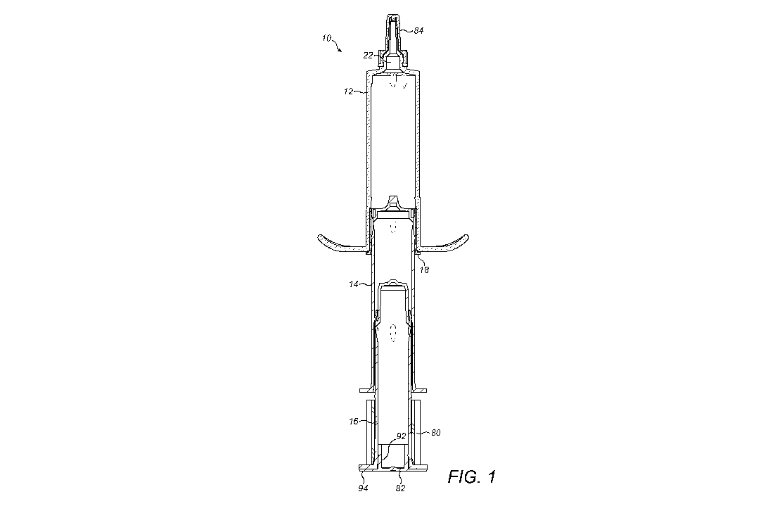
As shown in Figure 1, a device 10 in accordance with one
embodiment of the present invention comprises an outer
barrel 12, an inner barrel 14, a plunger 16, and a
protection ring 18. The device 10 also comprises a
releasable stop means 80, stop 82 and cap 84.
CA 02844022 2014-02-03
WO 2013/021186
PCT/GB2012/051900
- 8 -
As best seen in Figure 4, the outer barrel 12 comprises a
hollow cylindrical body 20, a dispensing nozzle 22 at the
distal end of the body 20 and an open proximal end
surrounded by a flange 24.
As shown in Figure 4, the inner bore of the outer barrel 12
comprises an enlarged diameter portion 26 at the proximal
end bounded by a shoulder 28, and a smaller diameter portion
30. In use, the enlarged diameter portion 26 receives and
retains the protection ring 18 and the smaller diameter
portion 30 defines a first chamber for receiving a first
composition.
At the distal end of the outer barrel 12, a number of
circumferentially spaced grooves 32 are formed in the inner
surface of the cylindrical body 20 and the end wall 34,
leading to the nozzle 22. In this example, three sets of
grooves are provided. As best seen in Figure 5, the grooves
32 may extend in a converging, arcuate fashion across the
end wall 34 towards the nozzle 22. These helical grooves 32
form flow channels which help the compositions to flow
towards the nozzle and empty the syringe.
Referring to Figures 6 and 7, the inner barrel 14 also
comprises a hollow cylindrical body 36. It has a closed
distal end 38 with a central projection 40 on the outer
surface and a corresponding recess 42 on the inner surface,
and an open proximal end surrounded by a flange 44. The
inner bore of the cylindrical body 36 includes a proximal
portion 46 of slightly larger diameter and a distal portion
48 of slightly smaller diameter, joined by a shoulder 50.
The proximal portion 46 may include a flared mouth 52 at the
CA 02844022 2014-02-03
WO 2013/021186 PCT/GB2012/051900
- 9 -
open end to assist with locating the plunger 16. The
proximal portion 46 may also include one or more axially
extending ridges or grooves 53 to assist with aligning the
plunger 16 as discussed further below. The distal end
portion 48 may include a further reduced diameter portion 54
adjacent the end wall 38 to receive the distal end of the
plunger 16.
As best seen in Figure 6, the outer surface of the inner
barrel 14 includes a waisted portion 56 of reduced outer
diameter close to the distal end. A number of
circumferentially spaced orifices 58 are provided in this
waisted portion 56 (see Figure 7). In this example, four
equi-spaced orifices 58 are provided, but this number may be
varied.
A flexible annular flange 86 is formed around the distal end
of the inner barrel 14. The flange 86 projects distally,
leaving an annular channel 88 between the flange 86 and the
outer surface of the distal end 38. The flange 86 is
sufficiently thin that it is flexible and deformable as
described further below.
The protection ring 18 is shown in Figure 8 at an enlarged
scale. This is initially located around the distal end of
the inner barrel 14 as shown in Figure 1. The protection
ring 18 comprises a tubular body 60 with a flange 62 around
the proximal end. The inner surface of the body 60 and outer
surface of the inner barrel 14 are provided with cooperating
structures 64 such as grooves and ribs, which serve to
locate the protection ring 18 on the inner barrel 14. As
shown in Figure 6, on the inner barrel 14 the structures 64
CA 02844022 2014-02-03
WO 2013/021186 PCT/GB2012/051900
- 10 -
are located proximally of the waisted portion 56, and the
flexible flange 86 is distal of it. The protection ring 18
covers this area when located on the inner barrel 14. The
structures 64 and the flexible flange 86 serve to seal the
protection ring 18 against the inner barrel 14 either side
of the orifices 58, to prevent leakage of liquid from the
inner barrel 14.
The plunger 16 is shown in Figures 9 and 10 and comprises a
cylindrical body 66. The proximal end includes a flange 68
against which a user exerts pressure in order to operate the
device 10. The flange 68 is illustrated relatively small and
flat but in practice this may be extended and formed curved
or otherwise ergonomically shaped to enhance comfort and
ease of operation for a user, in a similar manner to the
proximal end flange 24 of the outer barrel 12 which is
preferably enlarged and curved to comfortably and securely
fit a user's fingers to help in operating the device 10.
At the distal end of the plunger 16, is a reduced diameter
nose portion 72 with a central projection 74. A flexible
flange 70 is formed on the outer surface of the plunger 16
around the proximal end of the nose portion 72. In a similar
manner to the flexible flange 86 on the inner barrel 14, the
flange 70 projects distally, leaving an annular channel
between it and the nose portion. As seen in Figures 1-3,
when the plunger 16 is located in the inner barrel 14, the
flange 70 is deformed inwardly and forms a seal against the
inner wall of the body 37, to seal the proximal end of the
bore.
CA 02844022 2014-02-03
WO 2013/021186
PCT/GB2012/051900
- 11 -
The outer surface of the plunger 16 may include one or more
axially extending projections 90 (or ribs or grooves) to
cooperate with the ribs or grooves 53 in the inner barrel 14
to align and locate the plunger 16 in the inner barrel 14.
In conjunction with engagement of flange 70 against shoulder
50, the plunger 16 can be clipped into the inner barrel 14
as shown in Figure 1.
A stop 82 is fitted into the open proximal end of the
plunger 16 to close off the body 66, as seen in Figures 1-3.
The stop 82 comprises a tubular part 92, configured to be a
push fit with the interior of the body 66, and a flange 94
which provides a larger area for a user's thumb to press
against when depressing the plunger 16 to operate the
syringe 10.
A releasable stop means or clip 80 is releasably fitted
around the proximal part of the body 66 of the plunger 16,
as seen in Figures 1 and 2. As shown in Figure 11, the
releasable stop means 80 is preferably a resilient member
which is generally C-shaped in cross section, dimensioned to
securely fit around the plunger 16. Ridges 96 may protrude
from the releasable stop means 80 to provide gripping
features, enabling a user to push the releasable stop means
80 onto the plunger 16 and to pull it off again when
required.
A cap 84 is releasably clipped over the nozzle 22 of the
outer barrel 12 in order to seal the device 10 and prevent
leakage of fluid through the nozzle 22, and to keep the
nozzle 22 clean before use, as shown in Figure 1.
CA 02844022 2014-02-03
WO 2013/021186 PCT/GB2012/051900
- 12 -
When the device 10 is prepared and ready for use, a first
composition is held in the outer barrel 12 in a first
chamber defined by the smaller diameter portion 30. A second
composition is held in the inner barrel 14 in a second
chamber defined by the distal portion 48. The protection
ring 18 is sealingly located on the inner barrel 14 to
prevent leakage of the second composition which can exit the
second chamber via the orifices 58. The plunger 16 is
located in the proximal portion 46 of the inner barrel 14
with the flange 70 engaged against the shoulder 50. The
inner barrel 14 and protection ring 18 are located in the
proximal end of the outer barrel 12 with the protection ring
18 located in the larger diameter portion 26. The releasable
stop means 80 is located around a proximal portion of the
plunger 16. The nozzle 22 is covered by the cap 84. The
distal end of the plunger 16 is closed by the stop 82. Thus,
the device 10 is in the position shown in Figure 1.
In order to deliver the first composition, a user first
removes the cap 84 to expose the nozzle 22. The user then
exerts pressure against the end flange 94 of the stop 82.
Since the plunger 16 is located in the inner barrel 14 by
engagement of the flange 70 against shoulder 50, the plunger
16 and inner barrel 14 move as one unit into the outer
barrel 12. Thus, the first composition is displaced out of
the first chamber and passes through the nozzle 22 to exit
the device 10.
As the inner barrel 14 and plunger 16 move into the outer
barrel 12, the protection ring 18 is retained at the
proximal end of the outer barrel 12 in portion 26. Thus, the
inner barrel 14 and plunger 16 move as one unit through the
CA 02844022 2014-02-03
WO 2013/021186
PCT/GB2012/051900
- 13 -
ring 18. The flexible annular flange 86 is pressed against
the inner wall of the outer barrel 12, thereby preventing
leakage of the composition in the second chamber into the
first chamber. When the closed distal end 38 of the inner
barrel 14 reaches the distal end of the outer barrel 12, the
projection 40 is received in the nozzle 22 but does not
completely block it. An annular chamber 98 is formed between
the waisted portion 56 and the inner wall of the body 20 of
the outer barrel 12. This communicates with the grooves 32
formed in the outer barrel 12. The flexible flange 86 is
deformed by contact with the distal end wall of the outer
barrel 12. This allows the second composition to exit the
second chamber via orifices 58 and to flow via the annular
channel 98 and the grooves 32 in order to reach the nozzle
22. At this point, the releasable stop means 80 prevents
further movement of the plunger 16 into the inner barrel 14.
Thus, when required the user removes the releasable stop
means 80 and then exerts an increased pressure on the flange
68. This forces the base of the flange 70 to pass over the
shoulder 50 and allows the plunger 16 to move into the
distal portion 48 of the inner barrel 14. Thus, the second
composition is displaced out of the second chamber in the
inner barrel, via the orifices 58 and can flow through the
annular channel 98 and grooves 32 to the nozzle 22 for
delivery.
This releasable stop means for preventing movement of the
plunger into the second chamber can include the removable
clip as shown in Figures 1 and 11 and equivalents thereof.
The releasable stop means for preventing movement of the
plunger into the second chamber can also include one or more
depressible flanges or one or more depressible rings on the
CA 02844022 2014-02-03
WO 2013/021186
PCT/GB2012/051900
- 14 -
body of the plunger; a twist lock mechanism that requires
the plunger be rotated in relation to the barrel to allow
further movement of the plunger into the barrel; one or more
collapsible flanges or one or more collapsible rings that
collapse at a significantly higher force than that required
to move the plunger into the barrel in the absence of such
collapsible flanges or rings; one or more flanges, hinges,
or rings that are attached to the side of the body of the
plunger and which must be pulled away from the body of the
plunger to allow the plunger to move into the barrel, such
one or more flanges, hinges, or rings may remain attached to
at least a portion of the body of the plunger while still
allowing the plunger to move into the barrel; one or more
retractable flanges or rings that may be retracted by
pulling on an element located inside the body of the plunger
that is attached to said flanges or rings and protrudes from
inside the body of the plunger.
At the very end of the stroke, as in Figure 3, the nose 72
of the plunger 16 is located in the reduced diameter portion
54 at the distal end of the inner barrel 14 and the
projection 74 is received in the recess 42.
In practise, the first composition delivered may be an
antibiotic to treat mastitis in cattle and the second
composition may be a teat seal. It is desirable to inject
the antibiotic and then to massage the teat to ensure the
medication accesses it properly, before injecting the seal.
Therefore, the releasable stop means 80 provides the
advantage that the seal cannot be dispensed unintentionally
and will only be deliverable when a user is ready and has
removed the releasable stop means 80.
CA 02844022 2014-02-03
WO 2013/021186
PCT/GB2012/051900
- 15 -
Thus, a single device can be provided which contains first
and second compositions in separate chambers and does not
permit them to mix, but is able to sequentially deliver both
compositions by one full stroke of the plunger.