Note: Descriptions are shown in the official language in which they were submitted.
CA 02844408 2014-02-06
WO 2013/024065 1 PCT/EP2012/065803
Filtering apparatus and method for mixing, extraction and/or separation
The present invention relates to a filtering apparatus and method for mixing a
compound of solid and fluid phases, separating the phases and/or extracting
fluid from
the compound. In particular the invention may be applied in the mashing
process in a
beer brewing procedure.
Background of invention
The process for brewing beer based on grain, normally includes the steps of
malting,
milling, mashing, lautering, boiling, fermenting, conditioning and filtering.
Mashing
Mashing is the process of combining a mix of milled grain (typically malted
barley with
supplementary grains such as corn, sorghum, rye or wheat), known as the "grain
bill",
and water, known as "liquor", and heating this mixture in a vessel called a
"mash tun".
Mashing allows the enzymes in the malt to metabolise the starch in the grain
into
sugars, typically maltose to create a malty liquid called wort. Conventionally
there are
two main methods ¨ infusion mashing, in which the grains are heated in one
vessel;
and decoction mashing, in which a proportion of the grains are boiled and then
returned to the mash, raising the temperature. The mashing process which can
involve
pauses at certain temperatures, is normally performed in a "mash tun" which is
an
insulated brewing vessel. The end product of the mashing process is called a
"mash".
Historically a mash rake was used in the mashing process. The mash rake was an
instrument made of wood with a long handle, somewhat resembling an oar with
large
holes in the blade. The mash rake churns the mash to ensure that it is
appropriately
mixed and that the liquid can access the solid material in order to extract
sugar from
the solid material. Modern brewers, use mechanical power-rakes to mix the mash
instead of traditional manual mash rakes.
Mashing usually takes 1 to 2 hours, and during this time the various
temperature
pauses activate different enzymes depending on malt type, level of
modification and
the brewer's intentions. The enzyme activity converts starches of the grains
to dextrins
and then to fermentable sugars such as maltose. A mash pause or rest between
49-55
CA 02844408 2014-02-06
WO 2013/024065 2 PCT/EP2012/065803
C activates various proteases, which digest proteins to avoid protein clouding
of the
beer. This rest is generally used only with undermodified (undermalted) malts
which
are decreasingly popular in Germany and the Czech Republic, or non-malted
grains
such as corn and rice, which are widely used in North American beers. A mash
rest at
60 C activates 13-glucanase, which digests gummy 13-glucans in the mash, thus
causing the sugars to flow more freely later in the process. Finally, a mash
rest
temperature of 65-71 C is used to convert malt starches to sugar, which is
then
usable by the yeast during the fermentation part of the brewing process.
Duration of the
rests and varying pH also affect the sugar composition of the resulting wort.
Lautering
Lautering is the separation of the clear liquid wort (containing the sugars
extracted
during mashing) and the residual grain.
The lautering process usually consists of the three steps of mashout,
recirculation and
sparging.
Mashout is the term for raising the temperature of the mash to about 77 C
which stops
the enzymatic conversion of starches to fermentable sugars, and makes the mash
and
wort more fluid. The mashout step can be done by using external heat, or
simply by
adding hot water.
The recirculation step consists of drawing off wort from the bottom of the
mash, and
adding it to the top. Lauter tuns typically have slotted bottoms to assist in
the filtration
process. The mash itself functions much as a sand filter to capture mash
debris and
proteins. This step can be monitored by the use of a turbidometer to measure
solids in
the wort liquid by their opacity.
The sparging step is the trickling of water through the grain to extract
sugars. This step
is very sensitive to temperature and pH conditions as these paramenters may
result in
extraction of tannins from the grain husks resulting in a bitter brew.
Sparging is typically
conducted in a lauter tun.
In many commercial breweries sparging is performed by a continuous process
sparging meaning that when the wort reaches a desired level above the bed of
settled
CA 02844408 2014-02-06
WO 2013/024065 3 PCT/EP2012/065803
grain, water is added at the same slow rate that wort is being drained. The
wort thus
gradually becomes weaker and weaker, and at a certain point, addition of water
is
discontinued.
The lautering process is normally performed either in a mash tun fitted with a
false
bottom, a mash filter or most frequently in a lauter tun.
A lauter tun is the traditional vessel used for separation of the extracted
wort. While the
basic principle of its operation has remained the same since its first use,
technological
advances have led to better designed lauter tuns capable of quicker and more
complete extraction of the sugars from the grain.
A false bottom in a lauter tun has thin slits to hold back the solids and
allow liquids to
pass through. The settled solids rather than the false bottom form a
filtration medium
and retains small solid particles, allowing the otherwise cloudy mash to run
out of the
lauter tun as a clear liquid.
Run off tubes are evenly distributed across the bottom, with one tube
servicing about 1
m2 of area. Typically these tubes have a wide, shallow cone around them to
prevent
compaction of the grain directly above the outlet. Traditionally the run-off
tubes flowed
through swan-neck valves into a wort collection grant. This system led to
excessive
oxygen uptake and thus such systems have gradually been replaced either by a
central
wort-collection vessel or the arrangement of outlet ports into concentric
zones, with
each zone having a ring-shaped collection pipe. Public brewhouses however
often
maintain the swan-neck valves and grant for their visual effect.
Quality lauter tuns have rotating rake arms with a central drive unit.
Depending on the
size of the lauter tun, there can be between two and six rake arms. Cutting
blades hang
from these arms. The blade is usually wavy and has a plough-like foot. Each
blade has
its own path around the tun and the whole rake assembly can be raised and
lowered.
Attached to each of these arms is a flap which can be raised and lowered for
pushing
the spent grains out of the tun. The brewer, or better yet an automated
system, can
raise and lower the rake arms depending on the turbidity (cloudiness) of the
run-off,
and the tightness of the grain bed, as measured by the pressure difference
between
the top and bottom of the grain bed.
CA 02844408 2014-02-06
WO 2013/024065 4 PCT/EP2012/065803
There must be a system for introducing sparge water into the lauter tun. Most
systems
have a ring of spray heads that insure an even and gentle introduction of the
sparge
water. The watering system should not beat down on the grain bed and form a
channel.
Large breweries often have self-closing inlets on the bottom of the tun
through which
the mash is transferred to the lauter tun, and one outlet, also on the bottom
of the tun,
into which the spent grains fall after lautering is complete.
Some small breweries use a combination mash/lauter tun, in which the rake
system
cannot be implemented because the mixing mechanism for mashing is of higher
importance. The stirring blades can be used as a rake, however typically they
cannot
be moved up and down, and additionally they would disturb the bed too much
were
they used deep in the grain bed.
A lauter tun is disclosed in US 3,782,551 wherein wort is produced by
filtering mash in
a vessel with a filtering sleeve fixed to the vessel. The wort produced by the
vessel can
be removed in separated streams, and, in addition, an agitator is used for
mixing the
water and the mash.
Another solution discussing separation of wort from mash is described in US
4,844,932, where the mashing is carried out by use of a cross-flow separation
filter,
which filter may consist of a diameter shell within which a tubular filter is
housed. The
wort is produced in a four-step separation process wherein a reverse flow is
mentioned
in connection with the mash becoming resident on the filter or clogging the
pores of the
filter.
WO 98/20956 (Performance Pool Products Ltd) discloses a filter insert for a
water
filtration device. The insert is fixedly mounted inside a larger container.
Water can be
pumped into the filter insert, and be drawn from outside of the filter insert.
The flow can
be reversed (see figures 5a and 5b). The insert cannot be moved inside the
outer
container and cannot be removed without opening the container.
CA 02844408 2014-02-06
WO 2013/024065 5 PCT/EP2012/065803
US 3,782,551 (Soldan) discloses a lauter tub with a filter insert. The filter
is fixed inside
the lauter tub and defines an internal volume which is almost as large as the
internal
volume of the lauter tub.
US 4,793,243 (Lenz and Lenz) discloses a lauter tun with filter inserts that
can be
lowered into the lauter tun. The mash is present outside the filter inserts.
Furthermore,
the filter inserts have an open bottom. During lautering, liquid is drawn into
the filter
inserts and through a mesh in the bottom of the lauter tun. The filter inserts
serve to
increase the filter area.
DE 10 2008 039 374 (Krones AG) discloses a lauter tun with inserted tubes with
mesh
or filter walls. The inserted tubes serve to draw filtered liquid from the
lauter tun.
Pressure is applied to the lauter tun in order to increase the rate of
extraction. The
mash is placed outside the filter inserts. It appears that the liquid can be
circulated
through the lauter tun.
GB 1,149,476 discloses a clarifying tun for filtering brewer's mash comprising
a
container having inclined walls, wherein the container can be lowered into the
lauter
tun such that the inclined walls of the container are dispersed into the mash
of the
lauter tun. The wort is eluted through a discharge pipe at the top side of the
lauter tun.
Summary of invention
As in beer production an important aspect in many production processes is the
rate
and speed of extraction of a compound from a solid phase. In beer production
it is the
extraction of sugars. This is also the case in ethanol production. Thus, the
compound
may be of carbohydrates including sugars and pectin; polypeptides including
enzymes
and antibodies, glycosylated and unglycosylated proteins and peptides. The
solid
phase can be a plant material, sand, gravel or soil. The present invention
addresses
this issue by providing a novel apparatus and process for extraction of a
substance
from a solid phase. A first aspect of the invention discloses a filtering
apparatus
comprising a first filter section accommodating a first group of filter
members, and a
second filter section accommodating a second group of filter members, a piping
system
providing pipelined fluid communication between the filter sections and
between a filter
section and said filter section's corresponding group of filter members, the
piping
CA 02844408 2014-02-06
WO 2013/024065 6
PCT/EP2012/065803
system configured such that the filter members form filtered fluid openings of
the
filtering apparatus, and circulation means configured for passing fluid in a
forward flow
and/or in a reverse flow between the filter sections. In addition to the
filtering properties
of the present filtering apparatus, which is suitable for separating a liquid
and a solid
phase, the rate and/or speed of extraction of a substance from a solid phase
may be
increased. Any improvement in rate and/or speed of extraction may translate
directly
into lowered production costs.
The filter members may form the only fluid inlet openings of the filtering
apparatus, i.e.
the only fluid inlets of the present filtering apparatus is preferably trough
the filtered
openings in the filter members. Correspondingly the filter members may form
the only
fluid outlet openings of the filtering apparatus. However, in a further
embodiment liquid
outlet from the present filtering apparatus may be provided through non-
filtered outlet
openings. The non-filtered outlet opening may be part of the filter sections.
Furthermore, each of the filter sections may comprise a manifold, such as a
piping
manifold, for distributing fluid to the corresponding filter members.
Please note that the circulation means may be configured for passing fluid in
alternating directions.
A further aspect of the invention relates to a method for mixing a compound
comprising
a solid phase and a fluid phase and extracting fluid from said compound, the
method
comprising the steps of:
a) drawing fluid from the compound into a piping system through a first group
of
filtered openings in said piping system, said first group of filtered openings
located adjacent a first position in the compound,
b) guiding the fluid via the piping system to a second position in the
compound,
c) delivering the fluid to the compound through
- a second group of filtered openings in said piping system located
adjacent
said second position in the compound, or
- one or more non-filtered second outlet openings of the piping system
located
adjacent said second position in the compound,
d) optionally repeating steps a)-c), such as for a predefined period of time,
and
e) extracting fluid from the piping system.
CA 02844408 2014-02-06
WO 2013/024065 7 PCT/EP2012/065803
E.g. the method may be used for sucking fluid from the bottom of a vessel
containing
the compound, the fluid being filtered through the filtered openings, and
delivering the
fluid to the top of the compound in the vessel, either filtered through the
filtered
openings or delivered through the non-filtered openings. This may help to
increase the
mixing of the fluid and solid phases and possibly help to extract elements,
such as
sugars, from the solid phase into the fluid phase.
A further and related embodiment of the invention relates to a method for
mixing a
compound comprising a solid phase and a fluid phase and extracting fluid from
said
compound, the method comprising the steps of:
a) drawing fluid from the compound into a piping system through a first group
of
filtered openings in said piping system, said first group of filtered openings
located adjacent a first position in the compound,
b) guiding the fluid via the piping system to a second position in the
compound,
c) delivering the fluid to the compound through
- a second group of filtered openings in said piping system located
adjacent
said second position in the compound, or
- one or more non-filtered second outlet openings of the piping system
located
adjacent said second position in the compound,
f) alternating the direction of the fluid in the piping system thereby drawing
fluid
into the piping system through the second group of filtered openings, guiding
the fluid via the piping system to the first position in the compound and
delivering the fluid to the compound through
- the first group of filtered openings, or
- one or more non-filtered first outlet openings of the piping system located
adjacent said first position in the compound,
d) optionally repeating steps a)-e), such as for a predefined period of time,
and
e) extracting fluid from the piping system.
The first and second positions may be vertically displaced relative to each
other, e.g.
the first position may be at the bottom of the compound whereas the second
position
may be near the top of the compound. Furthermore, the first position and/or
the second
position may be displaceable relative to each other and/or relative to the
compound,
e.g. they may be translated up and down in the compound. To further increase
the
mixing between fluid and solid phases the first group of filtered openings
and/or the
CA 02844408 2014-02-06
WO 2013/024065 8 PCT/EP2012/065803
second group of filtered openings may be rotating relative to the compound,
thereby
furthermore functioning as agitator(s).
As above the method may be used for sucking filtered fluid from the bottom of
a vessel
containing the compound and be delivered at the top of the vessel. But here
the
method further includes the possibility of alternating the flow direction,
e.g. such that
filtered fluid can be sucked from the top of the vessel and delivered to the
bottom.
Thus, typically the filtered openings may function as both inlets and outlets
from the
piping system whereas the non-filtered outlet openings typically only
functions as
outlets. Thereby it may be ensured that only filtered fluid enters the piping
system.
Naturally the mixing and extraction method may be provided by means of the
herein
described filtering apparatus.
The process/method of the present invention can be used in beer brewing and
can
then be considered as consisting of three basic parts - mixing of a fluid and
a solid
phase, mashing, and final filtering, wherein the mashing is performed
throughout the
process under filtering conditions, and wherein the final filtering is
performed once the
wort has obtained the desired turbidity.
Conventional methods using modern filter press (frame filter) systems have the
disadvantage that the solid material such as malt or barley must be milled to
fine flour
in order to prevent extensive filter clogging. The milling into such fine
particles as flour
affects the taste and increases turbidity. To avoid these problems enzymes and
clarifying agents are often used.
When using the apparatus and the method of the present invention in a beer
brewing
process the malt or barley grain is normally split in halves or quarters.
While this grain
size would rapidly clog the filters of a conventional system, such as a frame
filter
system, no such clogging occurs in the apparatus of the present invention due
to its
construction, and the possible use of alternating fluid flow directions.
In this manner time-consuming rinsing of clogged filters can be avoided.
Additionally
use of unnecessary clarification and taste affecting additives can be avoided
in the
brewing process. Taken together, the present invention provides a cheaper
brewing
process and a more pristine brew without additives.
CA 02844408 2014-02-06
WO 2013/024065 9 PCT/EP2012/065803
While the present invention is particularly suitable for use in a beer brewing
process, it
can in principle be used for separating other organic and inorganic materials
such as
plant materials, gravel, soil and sand which are subjected to soaking e.g. for
extracting
compounds from the solid organic or inorganic material.
In one aspect the invention relates to a separation and/or extraction method,
which
method utilises the apparatus defined herein above, said method comprising the
steps
of:
a. arranging the filter apparatus in a vessel (1) by an arrangement means,
b. applying a fluid phase to the vessel,
c. operating the circulation means (5) to allow a forward or reverse flow
between the filter sections, and
d. optionally adjusting pH and temperature of the circulating fluid,
e. applying a solid phase to the vessel, and
f. optionally adjusting pH and temperature of the circulating fluid,
g. operating the circulation means (5) to allow flow in alternate directions
between the filter sections, and
h. optionally adjusting pH and temperature of the circulating fluid
i. repeat steps g and h until a desired turbidity of the fluid phase is
obtained,
j. eluting filtered fluid phase from the vessel (1), and
k. collecting the eluted filtered fluid phase.
Description of Drawings
Figure 1 shows the basic system with the first filter section (13) and the
second filter
section (14). In the illustrated example each filter section can be translated
along and
rotated around its respective axes A1 and A2. Each filter section accommodates
one or
more filter members indicated by (2) and (3), which can also rotate around
their axes
B1, B2.. .B and Ci, 02.. .0 respectively. The filter members (2, 3) are
illustrated as
perforated cylinders. I.e. liquid enters (and possibly exits) the filtering
apparatus
through the perforated cylinders which are functioning as filters. The filter
sections are
interconnected via a piping system (4) with a circulation means (5) capable of
CA 02844408 2014-02-06
WO 2013/024065 1 0 PCT/EP2012/065803
circulating fluid in alternate directions between the filter sections. A
piping manifold
distributes the liquid between a filter member (2, 3) and its corresponding
filter section
(13, 14).
Figure 2 shows an embodiment of the invention in which the apparatus of figure
1 has
been further equipped with a number of features useful in e.g. a beer brewing
process.
The means for controlling temperature (10) is used to control the fluid
temperature.
Manometers (15) and (16) determine the pressure on both sides of the
circulation
means and may be used to indicate when to alter the flow direction by
operating the
circulation means in the opposite direction. Grit may be added through the
mill (12). To
elute the system valve (6) is opened, and valve (7) is closed. The spent grain
can be
sparged through valve (11).
Figure 3 illustrates the apparatus with the filter sections placed in a vessel
(1).
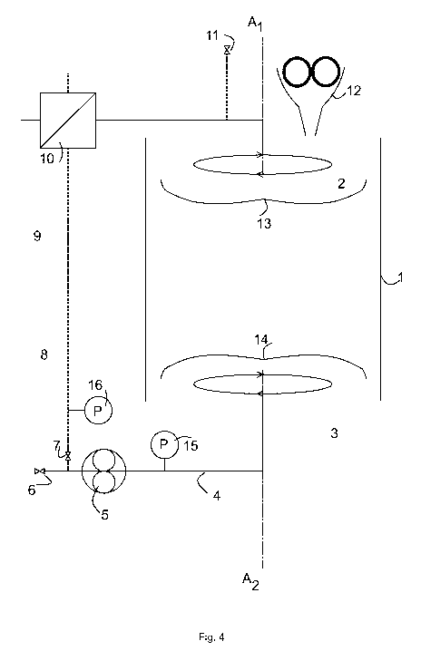
Figure 4 shows the system of figure 3, but where the filter sections (13) and
(14) rotate
around their respective axes A1 and A2.
Figure 5 shows the system of figure 4, but where the filter sections (13) and
(14)
additionally can be translated up and down along their respective axes A1 and
A2.
Figure 6 shows the system of figure 5, with the filter sections arranged
inside a vessel
(1) which is pressurized.
Figure 7 shows the system of figure 6, additionally equipped with a scraper
(18), to
scrape out the spent grain through hatch (17).
Figure 8 shows the system of figure 5, but utilizing filter members (2) and
(3) having a
flat configuration.
Figure 9 shows the system in figure 6 and/or 7, but with the filter members
(2) and (3)
rotating around their axes B1, B2... Bn and Ci, 02.. .0 respectively.
CA 02844408 2014-02-06
WO 2013/024065 11 PCT/EP2012/065803
Figure 10 shows the system in figure 6 and/or 7, but with the first (upper)
filter section
(13) rotating around its axis Al. This is useful during sparging to better
distribute the
sparging water, while keeping the lower filter arrangement (14) stationary.
Figure 11 shows the system in figure 6 and/or 7, but with all piping entering
the vessel
(1) through the lid. This is useful for retrofitting and old tanks.
Figure 12 shows the system in figure 11, but in an open vessel (1).
Figure 13 shows the system of figure 3, but where the bottoms (18) are
arranged on
the filter members by means of an elastic and/or resilient suspension (19).
Detailed description of the invention
Definitions
Mashing: The term mashing as used herein refers to the process of combining a
mix of
milled grain (typically malted barley with supplementary grains such as corn,
sorghum,
rye or wheat), known as the "grain bill", and water, known as "liquor", and
heating this
mixture in a vessel.
Vessel: The expression vessel as used herein is to be understood as a hollow
utensil,
such as a cup, vase, flask, tube, pitcher, tun, barrel, jug, tank or tub used
as a
container, especially for liquids or solid containing liquids.
Wort: The expression wort as used herein refers to the liquid extracted from
the
mashing process during the brewing of e.g. beer or whisky. Wort contains the
sugars
that will be fermented by the brewing yeast to produce alcohol.
Apparatus
As discussed herein above the apparatus of the invention is suitable for
extraction of
compounds such as carbohydrates from a solid phase such as plant material e.g.
malt,
to a fluid phase such as water. In particular the apparatus is capable of
increasing the
CA 02844408 2014-02-06
WO 2013/024065 12 PCT/EP2012/065803
rate and/speed of this extraction process before the final filtering is
executed. This is
provided by increasing flow of fluid around the solid material. The two (or
more) filter
sections, each accommodating a group of filter members are in fluid connection
with
each other through the piping system. The circulation means, such as a pump,
can
suck fluid into the piping system through the filter members. The circulation
means can
provide a flow in both directions (i.e. forward and backward) in the piping
system. In
one direction fluid is sucked into the piping system of the filtering
apparatus through the
filter members in the first filter section and leaves the filtering apparatus
through the
filter members in the second filter section. If the flow direction is reversed
the fluid is
correspondingly sucked into the piping system of the filtering apparatus
through the
filter members in the second filter section and leaves the filtering apparatus
through the
filter members in the first filter section. The apparatus may be adapted such
that fluid is
sucked into the piping system through a filtered opening but is pumped out
again
through a non-filtered outlet/opening. This may be provided by some sort of
valve
system or the filter members may be adapted to open when fluid is flowing out
of the
corresponding filter section.
The filtering apparatus is preferably adapted to be at least partly
incorporated in a
vessel. If the vessel is containing the fluid and solid phase and a compound
must be
extracted from the solid to the fluid phase the filtering apparatus can
therefore increase
the flow of fluid around the solid material and thereby increase the rate
and/or speed of
extraction of the compound from the solid and into the fluid. By furthermore
(periodically) alternating the flow direction in the piping system the mixing
between fluid
and solid is further increased and filter clogging may be reduced. If the
filter sections
are located at the top and bottom, respectively, of the fluid/solid phase the
filtering
apparatus is able to transport the fluid between top and bottom. If the filter
sections
and/or filter members are furthermore rotatable and/or translatable mixing is
further
increased and filter clogging may be further reduced.
The apparatus may in its basic form consist of a first and a second filter
section,
interconnected by an interconnector such as a tube or pipe. A circuit member
such as a
pump ensures circulation of a fluid phase between the filter sections. Each
filter section
comprises at least one filter member which may be in the form of a bell or a
flat filter.
Each filter section may be rotatable around its own central axis. Furthermore,
the filter
section may be able to be translated along the same axis. By this setup, the
apparatus
CA 02844408 2014-02-06
WO 2013/024065 13 PCT/EP2012/065803
of the invention is useful for separation of a solid and a fluid phase,
especially where
the solid phase upon is capable of settling in a fluid phase, thus forming a
bed of solid
material.
In a further embodiment the invention relates to a filtering apparatus for
separating a
liquid phase and a solid phase, and/or extracting a compound from the solid
phase to
the liquid phase, said filtering apparatus comprising
- rotatable and/or translatable first (13) and second (14) filter sections
accommodating one or more filter members (2,3),
- a piping system providing fluid communication between the filter sections,
and
- circulation means (5) configured for passing fluid in a forward flow (8)
and/or
in a reverse flow (9) between the filter sections.
During the separation and/or extraction process, it is often necessary to
force the solid
phase to form a bed of settled material. The apparatus achieves this by
alternating the
flow direction and simultaneously allowing rotation and/or translation of its
filter
sections.
In one embodiment of the present invention:
- the first filter section (13) is rotatable around and/or translatable
along an
axis A1, and
- the second filter section (14) is rotatable around and/or translatable
along an axis A2.
In one embodiment of the invention the axis A1 is equal or parallel to axis
A2.
The apparatus of the invention can be inserted in and removed from any
environment
where it can serve its purpose. Preferably the environment is a fluid
containing
environment such as a water course or a fluid containing vessel. Thus, in one
embodiment the apparatus is detachably arranged in a fluid containing
environment.
In a further embodiment the fluid environment is selected from, but not
limited to the
group consisting of a watercourse such as a lake, a sea, a river and a creek;
a slurry
tank including fertilizer slurries; and the vessel define herein, and wherein
the
apparatus is arranged such that the fluid may be circulated.
CA 02844408 2014-02-06
WO 2013/024065 14 PCT/EP2012/065803
Filter sections and filter members
As defined herein above the apparatus of the present invention comprises at
least a
first and a second filter section, each filter section comprising at least one
filter
member, preferably comprising a group of filter members, such as at least 2,
3, 4, 5, 6,
7, 8, 9, 10, 11, 12, 13, 14 or at least 15 filter members. The filter member
is preferably
in essence a filter arranged to filter a fluid phase thus separating the fluid
phase
passing through the filter member, from the solid phase unable to pass the
filter
member.
The filter member may comprise a container. Further, the filter member may
comprise
one or more filtration elements, i.e. the actual filtration is provided by the
filtration
element(s). A container such as bell-shaped, cylindrical or tubular container.
Examples
of filtration elements are surface filters, membrane filters, bell-shaped
filters or flat
filters. Possibly a filtration element is adapted to match a cross-section of
the container.
In one embodiment of the invention one or more or each of the filter members
comprise
a filtration element that forms the bottom or one or more sides of the filter
member.
In one embodiment of the invention the filter member is a perforated
container, such as
a perforated tube or a perforated elongated cylinder or a perforated elongated
tube
provided with a perforated or non-perforated bottom. The filtering function of
the filter
member is provided by the perforations and just as a normal flat filter the
filtering effect
is determined by the number and the size of the perforations. The filter
member may be
manufactured in steel, such as stainless steel. Compared to a standard surface
filter
the strength of a filter formed as a perforated tube is much greater and
filter formed as
a perforated tube is thereby able to withstand very high pressure. With a
plurality of
perforated tubes the total filter area of each filter section can be many
times higher
compared to normal flat filters. Thus, a filter section may comprise a piping
manifold
leading to a plurality of elongated perforated tubes provided with perforated
or non-
perforated bottoms, i.e. the filter members.
Each filter section may be rotatable and/or translatable around its own
central axis (A1
or A2). Additionally each filter member may optionally rotate around its own
central axis
(B1, B2... Bn or C1, C2¨Cn).
CA 02844408 2014-02-06
WO 2013/024065 15 PCT/EP2012/065803
Accordingly, in one embodiment of the apparatus of the invention, at least one
filter
member of the first filter section is rotatable around an axis B1, B2.. .B,
and/or the at
least one filter member of the second filter section is rotatable around an
axis Ci,
02.. .C, wherein n is the number of filter members.
The filtration element (i.e. the filter) of the filter member or the filter
members may have
any suitable shape. In one embodiment the filtration element of the apparatus
is a bell-
shaped filter or a flat filter.
The individual filtration elements of each filter section may be different
such that a filter
section simultaneously may accommodate one or more flat filters and one or
more bell-
shaped filters.
The bell shaped filters may be in the form of a traditional bell, a bell
formed from a one-
end-open cylinder or cube or in the form of a cone.
The filter members of the apparatus may each have a filter mesh size of 50-
1000 pm,
such as 60-900 pm, such as 70-800 pm, such as 80-700 pm, such as 90-600 pm,
such
as 100-500 pm, such as 150-450 pm, such as 200-400 pm, such as 250-350 pm,
such
as 275-325 pm, such as about 300 pm. The mesh size may differ from filter to
filter,
however, preferably the mesh size is similar in all filters of an apparatus.
Preferably the
mesh size of the filters is between 200-400 pm, more preferably between 250-
350 pm,
further preferably between 275-325 pm, most preferably about 300 pm. The
preferred
mesh sizes are especially preferred when procuring wort.
Each filter section comprises at least one filter member. In one embodiment
the filter of
the at least one filter member has openings of between 100 mm to 100 nm, e.g.
in the
range from 10 mm to 1 micrometer such as for instance 1 mm to 10 micrometer,
or in
the range from 500 micrometer to 100 micrometer, such as preferably 300
micrometer.
A problem that may arise with repeated use of the filter members is that the
filters/filtration elements/perforations may at least partly clog, e.g.
clogged by small
particles. Clogging may appear even though fluid enters the filtering
apparatus through
the filter members, i.e. through filtered openings. However, typically the
fluid is sucked
into the apparatus, i.e. fluid enters under a certain pressure and particles
may thus be
CA 02844408 2014-02-06
WO 2013/024065 1 6 PCT/EP2012/065803
sucked into the system through the filtered openings in the first filter
section, be
transported to the second filter sections and end up in one or more filter
members
where they are stopped by the filters and may consequently clog said filter
members.
Particles may be sucked into the system due to a high pressure. Particles
smaller than
the mesh size of the filters may collect in the system to form particles that
are greater
than the mesh size of the filters. And particles are not necessarily symmetric
and may
enter the filtering apparatus like a worm. Thus, rinsing of the filter members
may be
necessary even though the inlet openings are filtered.
The filters can be rinsed upon separation but that naturally requires a halt
in the filtering
and extraction process. A solution may be provided by a further embodiment of
the
invention wherein a part of a filter member is translatable, preferably
lengthwise
translatable, such as translatable along an axis substantially perpendicular
to the
longitudinal axis of said filter member. This abovementioned part of the
filter member
may e.g. be the top, bottom or a side of the filter member. It may also be a
filtration
element, e.g. a bottom forming a filtration element.
In one embodiment of the invention a part of the filter member is attached to
said filter
member by means of an elastic and/or resilient suspension. The suspension may
comprise one or more elastic and/or resilient elements, such as one or more
springs.
The suspension is preferably configured such that the suspending part can be
resiliently translated to open the filter member. I.e. if the suspending part
is the bottom
of the filter member, a translation of the bottom will open the filter member.
In one embodiment at least one filter member is adapted to open when a
predefined
level of positive pressure is present in said filter member. E.g. the
suspension is
configured to open the filter member when a predefined level of positive
pressure is
present in said filter member. This positive pressure may be created by a
combination
of fluid flowing through the filter member and clogging of the filter in said
filter member.
In a further embodiment a filter and/or bottom of a filter member is adapted
to be
resiliently translated (from a starting point) when fluid is flowing through
said filter
member in a first direction and the filter in said filter member is at least
partly clogged.
CA 02844408 2014-02-06
WO 2013/024065 1 7 PCT/EP2012/065803
In yet a further embodiment at least one filter member is adapted to open,
preferably
open resiliently, when fluid is flowing through said filter member in a first
direction and
the filter in said filter member is at least partly clogged. Said filter
member is preferably
adapted to close when fluid is flowing through in a second substantially
opposite
direction and/or when no fluid is flowing.
Thus, a filter member may be constructed to operate much like a check valve.
During
operation when the circulation means is pumping fluid through the system in
the
filtering process the filtration element / penetrations in a filter member may
become at
least partly clogged. The circulating fluid creates a positive pressure in the
filter
member. When the the filter member becomes at least partly clogged this
positive
pressure increases. The filter member may then be adapted to automatically
open, e.g.
by translating the filtration element or the bottom of the filter member. This
reduces the
positive pressure in the filter member allowing fluid to enter the filter
member and wash
out at least some of the particles clogging the filter. When the circulation
of fluid stops
or is reversed the filter member automatically closes and the filter member
has thus
been rinsed without separating any parts and without stopping the filtering
process.
The filter member may also be adapted to close after washout, because the
positive
pressure has been reduced upon opening of the filter member.
As stated above this may be achieved by attaching the top, bottom or the
filtration
element to the corresponding filter member by means of an elastic and/or
resilient
suspension. An example is illustrated in fig. 13 showing the system of figure
3, but with
the self-rinsing filter members. A filter member 17 is shown in close-up
comprising a
translatable filter bottom 18 attached to the filter member 17 by means of an
elastic
spring based suspension mechanism 19. The filter bottom 18 (comprising a
filtration
element) can be translated up and down along the longitudinal direction of the
filter
member 17. In the closed configuration to the right the filter member 17 is
closed and
the springs in the suspension mechanism 19 are in a relaxed state. When
positive
pressure is building up inside the filter member 17 due to fluid flow and
clogging of the
filter bottom 18 the filter member 17 will gradually open because the filter
bottom 18 is
gradually translated downwards due to the increasing positive pressure. Fluid
can then
enter the open filter member 17 from the tank 1 and washout small particles
clogged in
the filter bottom. When the pressure inside the filter member 17 is reduced
the
CA 02844408 2014-02-06
WO 2013/024065 18 PCT/EP2012/065803
suspension 19 closes the filter member 18. In the illustrated example the
bottom 18 is a
filter bottom. It could also be a non-filtered solid bottom.
Vessel
The apparatus of the present invention is preferably arranged and used as an
insert or
addition to a vessel and can thus be mounted or arranged e.g. on existing
brewing
equipment which is economical for the intended user.
The apparatus may be arranged by an arrangement means which may be any means
suitable for arranging the apparatus including a rigid pipe system used in the
circulation
of the fluid, or by a scaffold. The skilled person is competent to design an
arrangement
means suitable for his purpose.
Accordingly, in one embodiment the apparatus as defined herein above further
comprises a vessel. The vessel may e.g. be a one end open vessel or a closed
vessel.
The apparatus of the present invention mounted in a closed vessel is useful in
a
pressurised brewing process.
The vessel can be any kind of vessel suitable of accommodating the apparatus
of the
invention. Thus, in one embodiment the vessel is selected from the group
consisting of
a tun, a cup, a vase, a flask, a tube, a pitcher, a barrel, a jug, a tank, a
container, a
cone and a tub. In one embodiment the vessel is a lauter tun or mash tun.
The vessel of the apparatus described herein may have any suitable size. The
vessel
may have a length from the first end to the second end of at least 50 cm, such
as at
least 75 cm, such as at least 1 m, such as at least 1.5 m, such as at least 2
m, such as
at least 2.5 m, such as at least 3 m, such as at least 3.5 m, such as at least
4 m, such
as at least 5 m, such as at least 6 m, such as at least 7 m, such as at least
8 m, such
as at least 9 m, such as at least 10 m.
The size of a separation apparatus is usually described in respect to the
volume of the
tanks, the vessel of the apparatus described herein may have a volume of 5,000
to
1,000,000 liter, such as 10,000 to 800,000 liter, such as 15,000 to 600,000
liter, such
as 20,000 to 400,000 liter, such as 25,000 to 200,000 liter, such as 30,000 to
100,000
liter, such as 35,000 to 80,000 liter, such as 40,000 to 70,000 liter.
CA 02844408 2014-02-06
WO 2013/024065 1 9 PCT/EP2012/065803
The overall diameter of the transverse section of the vessel is at least 25
cm, such as
at least 50 cm, such as at least 75 cm, such as at least 1 m, such as at least
1.5 m,
such as at least 2 m, such as at least 2.5 m, such as at least 3 m, such as at
least 3.5
m, such as at least 4 m, such as at least 5 m, such as at least 6 m, such as
at least 7
m, such as at least 8 m, such as at least 9 m, such as at least 10 m.
Solid and fluid phases
The apparatus is designed for mixing a solid and a fluid phase, separating a
solid and a
fluid phase, extracting fluid, and/or to extract a compound from the solid
phase to the
fluid phase.
Thus in one embodiment the invention relates to the use of the apparatus for
extracting
compounds from the solid phase using the fluid phase.
The solid phase may be added to the apparatus, such as to the vessel defined
herein
above, and to/in/on which the apparatus is arranged. Thus, the apparatus of
the
invention in one embodiment further comprises at least one unit for supplying
the solid
phase.
The fluid phase may be added to the apparatus, such as to the vessel in/on
which the
apparatus is arranged. Thus in one embodiment the apparatus as described
herein
above further comprises at least one unit for supplying the fluid phase.
In one embodiment the at least one unit for supplying the solid and/or fluid
phase is
selected from the group consisting of a mill, a funnel, a tube and a pipe, a
bucket, a
beaker, a mixer and a roller.
The fluid phase can be selected from but is not limited to the group
consisting of water,
milk, organic solvents and aqueous cell culture media.
In one embodiment the compound extracted from the solid phase is selected from
the
group consisting of carbohydrates including sugars and pectin; polypeptides
including
enzymes and antibodies, glycosylated and unglycosylated proteins and peptides;
oil
CA 02844408 2014-02-06
WO 2013/024065 20 PCT/EP2012/065803
and aroma.
The solid phase may be selected from malt and/or barley which can be rolled,
crushed
or milled prior to addition to the apparatus. The solid phase may also be a
plant
material, sand, gravel or soil.
In principle the apparatus can also be used as a fermentor, in which case
microorganisms may be immobilized on a particle. The apparatus is then used as
a
large agitator and the flow between the filter sections ensure appropriate
agitation and
supply of nutrients to the cultured microorganisms.
The particles of the solid phase may then be e.g. a bio-bead. Thus in one
embodiment
the solid phase consists of biobeads. In a further embodiment microorganisms
have
been immobilised on the biobeads. In a further embodiment the microorganisms
are
capable of producing ethanol from a compound or substance in the vessel of the
apparatus.
Another particle that could form the solid phase is any colloid such as
colloid gold
particles which in turn may be coated by other entities having affinity for
the colloid gold
particle.
Valves, pipes and circulation means
In order to regulate the flow and benefit from the advantages of the apparatus
of the
present invention it may be useful to equip both the apparatus as described
herein
above and the vessel, with valves and pipes. The valves and additional pipes
may be
arranged as described in any of figures 1 to 12.
In one embodiment the apparatus of the present invention comprises at least
one
valve. Similarly, the apparatus or vessel described herein above may comprise
any
number of valves and pipes in order to facilitate flow of filtered fluid in
forward or
reverse direction, or in order to fill or elute fluid fractions from the
apparatus and/or
vessel.
CA 02844408 2014-02-06
WO 2013/024065 21 PCT/EP2012/065803
The fluid flow in a forward or a reverse direction is accommodated for by a
circulation
means which preferably is one or more pumps.
Circulation of fluid between the first and the second filter section, or
between the
second and the first filter section are achieved by a circulation means such
as a pump.
The apparatus of the invention may comprise one or more pumps to obtain the
circulating flow of fluid. Optionally valves may be used to direct the fluid
during
circulation and to perform certain processes requiring an enhanced control of
flow rate
and direction.
In one embodiment the apparatus of the invention is arranged so that the
contents of
the vessel may be circulated.
It is often advantageous to be able to adjust the pressure of the fluid
circulated
between the first and the second or between the second and the first filter
section.
Thus in one embodiment the apparatus comprises means for adjusting the
pressure.
The means for adjusting the pressure may be capable of adjusting the pressure
to 0,1
to 100 mbar, such as 50 mbar to 1 bar, such as 1 to 20 bar, such as 2 to 15
bar, e.g. 3
to 10 bar, such as 4 to 8 bar.
In one embodiment the means for adjusting pressure is arranges such that the
means
for circulating fluid alters direction when a certain predefined pressure has
beeen
reached, thus avoiding clogging of filters.
Valves may also be utilised to facilitate a process performed under
pressurized
conditions in a closed vessel. Pressurized conditions may be obtained by using
a gas
phase such as air, N2 (g) or CO2 (g).
The pipe system of the apparatus can be connected such that it can direct
fluid in a
loop outside of a vessel and between the first and second filter sections.
Preferably the
pipe system can direct fluid in either way between the first and the second
filter section.
To make it possible for the fluid in the apparatus to flow in the pipes, the
apparatus or
the pipe system comprises at least one circulation means such as a pump, the
CA 02844408 2014-02-06
WO 2013/024065 22 PCT/EP2012/065803
circulation means being capable of directing fluid in alternating directions.
By changing
the direction of the flow alternating direction of flow of fluid can be
obtained. The
number of circulation means may be any suitable, such as one, two, three,
four, five,
six or seven or more.
Each circulation means of the apparatus may be capable of turning or reversing
the
direction of fluid within the apparatus at least every 30 seconds, such as at
least every
45 seconds, such as at least every minute, such as at least every 11/2
minutes, such as
at least every 2 minutes, such as at least every 21/2 minutes, such as at
least every 3
minutes, such as at least every 31/2 minutes, such as at least every 4
minutes, such as
at least every 41/2 minutes, such as at least every 5 minutes. Preferably the
flow
direction is changed or reversed with an interval of between 2 to 4 minutes.
In another
preferred embodiment of the method, the flow direction is changed or reversed
with an
interval such that when a volume corresponding to the volume of liquid in the
apparatus
has passed one way through the apparatus, the flow direction is changed or
reversed.
The circulation means may be capable of circulating fluid through the system
at a rate
of at least 1 m3/h, such as at least 2 m3/h, such as at least 3 m3/h, such as
at least 4
m3/h, such as at least 5 m3/h, such as at least 6 m3/h, such as at least 7
m3/h, such as
at least 8 m3/h, such as at least 9 m3/h, such as at least 10 m3/h, such as at
least 15
m3/h, such as at least 20 m3/h, such as at least 25 m3/h, such as at least 30
m3/h, such
as at least 35 m3/h, such as at least 40 m3/h, such as at least 45 m3/h, such
as at least
50 m3/h, such as at least 55 m3/h, such as at least 60 m3/h, such as at least
70 m3/h,
such as at least 80 m3/h, such as at least 90 m3/h, such as at least 100 m3/h.
In one embodiment the apparatus as defined herein above further comprises
pumps,
valves and pipes to provide a closed system. Further, in one embodiment the
apparatus and/or vessel further comprises a draining means, such as a valve
for
draining. In a further embodiment the apparatus further comprises a yeast
tank.
In another embodiment the invention may comprise at least one agitator. The
agitator
is preferably used in a vessel. In one embodiment the agitator is the first
filter section
(13) rotatable around axis Al. In another embodiment the agitator is the
second filter
section (14) rotatable around axis A2. In one embodiment both the first and
second filter
sections acts as agitators. In yet another embodiment each filter member acts
as an
CA 02844408 2014-02-06
WO 2013/024065 23 PCT/EP2012/065803
agitator. Accordingly, in one embodiment the agitator is the at least one
filter member
of the first filter section, and/or the agitator is the at least one filter
member of the
second filter section.
Means for controlling temperature
To control the process for which the apparatus is used, the apparatus may
further
comprise heating means and means for controlling temperature. The heating
means
may be arranged as a part of the circuit as described in the drawings, however
the
heating means or means for controlling temperature may also be arranged such
that
the vessel defined herein above, is heated or cooled such that any content of
the
vessel is accordingly heated or cooled. The means for controlling temperature
is
particularly suitable for enhancing the efficiency of an extraction process in
beer
brewing.
In one embodiment the apparatus of the invention comprises a means for
controlling
temperature. In one embodiment said means for controlling temperature is a
heat
exchanger. The means for controlling temperature normally also comprises a
means
for measuring the temperature.
The means for controlling temperature may be capable of heating the
circulating fluid of
the apparatus to a temperature below 100 C, such as below 90 C, such as below
80 C, such as below 70 C, such as below 60 C, such as below 50 C. Preferably
the
means for controlling temperature is capable of adjusting the temperature of
the fluid to
a temperature between 20 and 100 C, such that the variation is less than about
2 C
from a predetermined temperature.
In one embodiment the means for adjusting temperature is capable of adjusting
the
temperature of substances within the apparatus to a temperature of 0 to 200
C, e.g. in
the range from 20 to 90 C, preferably in the range from 40 to 80 C, such as
100 to
200 C, e.g. such as 100 to 150 C, such as 100 to 125 C.
Integration in auxiliary equipment
The apparatus of the present invention can be integrated in auxiliary
equipment in e.g.
a brewery. The apparatus may for example be arranged in its entirety in or on
an
existing vessel such as a tank. Each filter section may additionally be
integrated in, or
CA 02844408 2014-02-06
WO 2013/024065 24 PCT/EP2012/065803
mounted on a tank cleaner. The tank cleaner may be a conventional tank cleaner
such
as Toftejorg (http://www.csidesigns.com/alfalaval/toftejorgdahp).
Applications of the apparatus
The apparatus as described herein can be used to extract substances for every
type of
material including plant material which can be withhold by the filters of the
apparatus
without blocking the filter such that a fluid flow can be obtained. Other
types of
applications are for bulking or swelling of seeds or kernels; for removal of
unwanted
components or substances from e.g. a plant material e.g. removal of water-
soluble
substances from a plant material; for fermentation; for partial degradation
e.g. enzyme
treatment of straw in a process similar to the production of wort.
The apparatus as described herein may also be used for treatment of straw.
Straw may
be treated before used for the production of bio-ethanol. Straw may be treated
to
remove lime from the plant material. Also sugar cane can be the plant material
treated
in the apparatus described herein. Sugar can thus be extracted from the plant
material.
In one embodiment the apparatus is a mashing apparatus. Preferably the mashing
apparatus is for producing wort in a beer brewing process.
In the separation apparatus described herein the components of the apparatus
may be
made of a material suitable in the production of beverages or food, such
material may
be selected from polymers or metals.
Separation and extraction method
In another aspect the invention relates to a separation and/or extracting
method for
separation and/or extracting substances from a plant material, the method
comprises
the step of
= Providing plant material,
= Providing a volume of fluid,
= Bringing the plant material and the fluid in contact with each other,
such
that the fluid at least for a period is subjected to being directed through
the plant material in alternating direction,
CA 02844408 2014-02-06
WO 2013/024065 25 PCT/EP2012/065803
= Hereby separating and/or extracting substances from the plant material,
and
= Separating the fluid with the separated and/or extracted substances
and/or compounds from the plant material.
Plant material suitable to be used in an extraction process as described
herein is plant
material which can be withhold by the described filters without blocking the
filter such
that a liquid flow within the apparatus can be obtained. The plant material
can be
selected from the group of seeds, flowers, leafs, stems, and roots. Plant
material can
be selected from the group of seeds obtained from barley, wheat, rye, oat,
corn
(maize), and rice. The plant material can have any suitable size, such as a
size less
than 10 mm, such as less than 9 mm, such as less than 8 mm, such as less than
7
mm, such as less than 6 mm, such as less than 5 mm, such as less than 4 mm.
The plant material may be chopped, grinded, milled, pulverised, and/or
flattened before
it is brought into contact with the liquid. The plant material may be treated
with water
before it is chopped, grinded, milled, pulverised, and/or flattened. The plant
material
may also be treated with water while it is being chopped, grinded, milled,
pulverised,
and/or flattened.
The liquid of the method can be selected from water or alcohol. Preferably the
liquid is
water.
The ratio of plant material and liquid in the method can be from 1:1 to 1:100
when
measuring the weight of both the plant material and liquid, the ratio may be
such as
between 1:1 to 1:50, such as between 1:1 to 1:25, such as between 1:1 to 1:15,
such
as between 1:1 to 1:10, such as between 1:1 to 1:5, such as between 1:1 to
1:4, such
as between 1:1 to 1.3, such as between 1:1 to 1:2. In a process for producing
wort the
ratio of plant material e.g. grains and/or malt to water is preferably between
1:1 to 1:3,
more preferably between 1:1 to 1:2.
The method as described herein may be performed such that the plant material
and
liquid is in contact with each other until a predetermined level of substances
is obtained
within the liquid. The substances to extract from plant material may be sugar
and/or dry
matter.
CA 02844408 2014-02-06
WO 2013/024065 26 PCT/EP2012/065803
In the method the plant material and fluid may be in contact with each for at
least 10
minutes, such as at least 20 minutes, such as at least 30 minutes, such as at
least 40
minutes, such as at least 50 minutes, such as at least 60 minutes, such as at
least 90
minutes, such as at least 2 hours, such as at least 2% hours, such as at least
3 hours,
such as at least 3% hours, such as at least 4 hours, such as at least 4%
hours, such as
at least 5 hours, such as at least 6 hours, such as at least 7 hours, such as
at least 8
hours, such as at least 9 hours, such as at least 10 hours, such as at least
20 hours,
such as at least 30 hours, such as at least 40 hours, such as at least 50
hours, such as
at least 60 hours, such as at least 70 hours, such as at least 80 hours, such
as at least
90 hours, such as at least 100 hours, such as at least 150 hours, such as at
least 200
hours, such as at least 300 hours, such as at least 400 hours, such as at
least 500
hours, such as at least 600 hours.
The fluid may be directed through the plant material in alternating direction.
The
direction of the fluid may be altered at least every 30 seconds, such as at
least every
45 seconds, such as at least every minute, such as at least every 1% minutes,
such as
at least every 2 minutes, such as at least every 2% minutes, such as at least
every 3
minutes, such as at least every 3% minutes, such as at least every 4 minutes,
such as
at least every 4% minutes, such as at least every 5 minutes. More preferably
the flow
direction is reversed or altered when a volume of fluid corresponding to the
volume of
fluid within the apparatus has passed one way through the apparatus. Thus if
the
velocity of the flow is increased, the time until reversal of the flow
direction is increased.
When performing the method the direction of the fluid is altered at least 5
times, such
as at least 10 times, such as at least 15 times, such as at least 20 times,
such as at
least 25 times, such as at least 30 times, such as at least 35 times, such as
at least 40
times, such as at least 45 times, such as at least 50 times, such as at least
55 times,
such as at least 60 times, such as at least 65 times, such as at least 70
times, such as
at least 75 times, such as at least 80 times, such as at least 85 times, such
as at least
90 times, such as at least 95 times, such as at least 100 times, such as at
least 125
times, such as at least 150 times, such as at least 175 times, such as at
least 200
times, such as at least 250 times, such as at least 300 times, such as at
least 350
times, such as at least 400 times, such as at least 450 times, such as at
least 500
times.
CA 02844408 2014-02-06
WO 2013/024065 27 PCT/EP2012/065803
In one aspect the invention relates to a separation and/or extraction method,
which
method utilises the apparatus defined herein above, said method comprising the
steps
of:
a. arranging the filter apparatus in a vessel (1) by an arrangement means,
b. applying a fluid phase to the vessel,
c. operating the circulation means (5) to allow a forward or reverse flow
between the filter sections, and
d. optionally adjusting pH and temperature of the circulating fluid,
e. applying a solid phase to the vessel, and
f. optionally adjusting pH and temperature of the circulating fluid,
g. operating the circulation means (5) to allow flow in alternate directions
between the filter sections, and
h. optionally adjusting pH and temperature of the circulating fluid
i. repeat steps g and h until a desired turbidity of the fluid phase is
obtained,
j. eluting filtered fluid phase from the vessel (1), and
k. collecting the eluted filtered fluid phase.
In one embodiment of the separation and/or extraction method the circulation
member
(5) is operated to allow a flow in a certain direction during a pre-defined
period of time,
or within a pre-defined pressure range.
Regulation of temperature may be important for maximizing extraction of a
compound
from the solid phase. The temperature may be adjusted to at least 4 C, such as
5 C,
such as, 6 C, such as, 7 C, such as 8 C, such as 9 C, such as 10 C, such as 15
C,
such as 20 C, such as 25 C, such as 30 C, such as 35 C, such as 37 C, such as
40 C, such as 45 C, such as 50 C, such as 51 C, such as 52 C, such as 53 C,
such
as 54 C, such as 55 C, such as 56 C, such as 57 C, such as 58 C, such as 59 C,
such as 60 C, such as 61 C, such as 62 C, such as 63 C, such as 64 C, such as
65 C, such as 66 C, such as 67 C, such as 68 C, such as 69 C, such as 70 C,
such
as 71 C, such as 72 C, such as 73 C, such as 74 C, such as 75 C, such as 76 C,
such as 77 C, such as 78 C, such as 79 C, such as 80, such as 81 C, such as 82
C,
such as 83 C, such as 84 C, such as 85 C, such as 86 C, such as 87 C, such as
88 C, such as 89 C, such as 90 C, such as 91 C, such as 92 C, such as 93 C,
such
CA 02844408 2014-02-06
WO 2013/024065 28 PCT/EP2012/065803
as 94 C, such as 95 C, such as 96 C, such as 97, such as 98 C, such as 99 C,
such
as 100 C or more.
In one embodiment of the method defined herein above the pre-defined period of
time
ranges from 1 second to 10 hours, such as from 10 seconds to 5 hours, such as
from
30 seconds to 1 hour, such as from 30 seconds to 45 minutes, such as from 45
seconds to 30 minutes, e.g. 20 minutes, such as from 1 minute to 15 minutes,
such as
minutes, e.g. from 1 minute to 10 minutes, such a from 1 minute to 5 minutes
such
as 5 minutes, e.g. from 2 minutes to 4 minutes, such as 3 minutes.
The pressure is adjusted by the force of the circulation means. As mentioned,
it is
advantageous to program the circulation means such that the fluid flow is
altered when
a certain pressure range is exceeded. In one embodiment the pre-defined
pressure
range is from 0.1 mbar to 100 bar, preferably from 0.5 bar to 10 bar, more
preferably
from 1 bar to 5 bars.
For certain applications it is advantageous to use the filter members for
agitating the
contents of a vessel in which the apparatus of the invention is mounted. Thus,
in one
embodiment of the method defined herein above any of steps c to j further
comprises
simultaneously or sequentially translating the first filter section along A1
and/or
translating the second filter section along A2,
and/or
rotating the first filter section around A1 and/or rotating the second filter
section
around A2.
In one embodiment the at least one filter member (2) of the first filter
section (13)
rotates around its own axis B1. In a further embodiment the at least one
filter member
(2) of the second filter section (13) rotates around its own axis C1.
The force applied to the plant material by the fluid being directed in a first
or second
direction may be the force provided by the flowing fluid and gravity or
buoyancy.
The fluid and/or the plant material may be heated to a predetermined
temperature
before initiation of the period where the fluid is subjected to circulation
through the
CA 02844408 2014-02-06
WO 2013/024065 29 PCT/EP2012/065803
apparatus and thus through the plant material. The fluid may also be heated
while
bypassing the plant material.
The predetermined temperature of the fluid or of the fluid and plant material
can be
selected from temperatures in the range of 20 to 100 C, such as in the range
of 30 to
90 C, such as in the range of 40 to 80 C, such as in the range of 50 to 70 C,
such as
in the range of 55 to 65 C.
The predetermined temperature may be any temperature preferably below 100 C,
examples of temperatures can be about 20 C, such as about 25 C, such as about
30 C, such as about 35 C, such as about 40 C, such as about 45 C, such as
about
50 C, such as about 55 C, such as about 60 C, such as about 65 C, such as
about
70 C, such as about 75 C, such as about 80 C, such as about 85 C, such as
about
90 C, such as about 95 C.
The temperature may be changed during the process. E.g. a process of producing
wort
when brewing beer may be initiated by a few minutes at 45 C to bulk or swell
the
grains or malt. After this the temperature can be increased to 53-58 C for 20-
30
minutes, then 63-68 C for 30 minutes to 1 hour, then about 78 C for a few
minutes to
inactivate the enzymes. After this the fluid is drained from the plant
material and the
plant material is rinsed with water. Other processes with different
temperatures are also
possible with the method and apparatus as described herein.
In the separation or extraction method all the features of the method as
described
herein may be combined with all the features of the apparatus as described
herein.
Preferably the plant material used in the method comprises grain and/or malt
and the
fluid is preferably water.
In another aspect the invention relates to a method for producing a separation
apparatus as described herein, the method comprises
= Providing at least a first and a second filter section,
= Providing at least a first and a second filter member,
= Providing at least one piping system
CA 02844408 2014-02-06
WO 2013/024065 30 PCT/EP2012/065803
= Providing a circulation means for circulating fluid through the piping
system,
= Connecting the first filter section to the first filter member
= Connecting the first filter section to one end of the piping system
= Connecting the second filter section to the second filter member
= Connecting the second filter section to the other end of the piping
system
= Arranging the circulation means such that it is capable of directing
fluid
between the first and the second filter sections.
= Hereby obtaining a separation apparatus.
Examples
Example 1: Method of making beer using the apparatus of the invention
1. The apparatus of the invention is mounted on a vessel.
2. 200 litres of cold tap water is added to the vessel through the valve for
supply of
fluid (11).
3. The circuit member (5) is operated to allow flow in the flow direction (8),
i.e.
from the bottom to the top of the vessel.
4. The means for adjusting temperature (10) is operated at a temperature of 80
C
thus achieving a temperature of the fluid exiting from the means for adjusting
temperature of about 54 C.
5. The operation of the means for adjusting temperature is discontinued.
6. 40 kg of the solid phase such as crushed, rolled or milled malt or barley
is
added to the vessel via the means for addition of solid material (12). *
7. pH is adjusted to about 5,8.*
8. The temperature of the fluid phase is adjusted by operating the means for
adjusting temperature (10) at a temperature of 55 C thus achieving a
temperature of the fluid exiting from the means for adjusting temperature of
about 54 C.*
9. The flow direction is altered between flow direction (8) and (9) every 3
minutes,
or when the pressure is below e.g. 0,5 bar.*
10. Step 9 is maintained for 20 minutes. *
CA 02844408 2014-02-06
WO 2013/024065 31 PCT/EP2012/065803
11. The means for adjusting temperature (10) is operated at a temperature of
65 C
thus achieving a temperature of the fluid exiting from the means for adjusting
temperature of about 64 C. *
12. The system is maintained as in step 9 for 60 minutes. *
13. The means for adjusting temperature (10) is operated at a temperature of
80 C
thus achieving a temperature of the fluid exiting from the means for adjusting
temperature of about 78 C. *
14. The system is maintained as in step 9 for 5 minutes. *
15. Fluid is circulated by operating the curcuit portion to allow flow in the
direction
(8) until an appropriate turbidity of the wort (the fluid processed to become
beer)
is obtained.
16. When the appropriate turbidity has been obtained, valve (6) is opened and
valve (7) is simultaneously closed.
17. 50 litre of 70 C water is added through valve (11) when the surface of the
fluid
phase has reached the surface of the solid phase in the vessel.
18. The vessel is emptied by operating the circuit portion and valves suitable
for
emptying the vessel.
19. The vessel is cleaned by e.g. adding water through valve (11) and
operating the
circuit member (5)
20. The system is ready for receiving new raw materials (solid and fluid
phases)
and to produce an additional brew.
During the steps indicated by asterisk (*) above, the first filter section
rotates
around axis Al, and translates from top to bottom of the vessel along axis
Al.*
Optionally, the at least one filter member (13) of the first filter section
(2) rotates
around its axis Bl.
Further details of the invention
The invention will now be explained in further details with reference to the
following
items:
1. A filtering apparatus comprising
CA 02844408 2014-02-06
WO 2013/024065 32 PCT/EP2012/065803
- a first filter section (13) accommodating a first group of filter members
(2),
and
- a second filter section (14) accommodating a second group of filter
members (3),
- a piping system providing pipelined fluid communication between the
filter
sections and between a filter section and said filter section's corresponding
group of filter members, the piping system configured such that the filter
members (2,3) form filtered fluid openings of the filtering apparatus, and
- circulation means configured for passing fluid in a forward flow (8)
and/or in
a reverse flow (9) between the filter sections.
2. The filtering apparatus of item 1, wherein the filter members (2, 3) form
the only
fluid inlet openings of the filtering apparatus.
3. The apparatus of any of the preceding items, wherein the filter sections
(13, 14)
are rotatable and/or translatable.
4. The apparatus of item 3, wherein
- the first filter section (13) is rotatable around and/or translatable
along an
axis Ai, and
- the second filter section (14) is rotatable around and/or translatable
along an
axis A2.
5. The apparatus of item 4, wherein A1 is equal or parallel to A2.
6. The apparatus of any of the preceding items, wherein the circulation means
is
configured for passing fluid in alternating directions (8, 9).
7. The apparatus of any of the preceding items, wherein the apparatus is
adapted
for extracting a compound from a solid phase to a fluid phase.
8. The apparatus of any of the preceding items, wherein the apparatus is
adapted
for separating a fluid phase and a solid phase.
CA 02844408 2014-02-06
WO 2013/024065 33 PCT/EP2012/065803
9. The apparatus of any of the preceding items, wherein the apparatus is
adapted
to be a mobile filtering apparatus.
10. The apparatus of any of the preceding items, wherein the filter sections
are
adapted to be incorporated, integrated and/or submerged in a single vessel.
11. The apparatus of any of the preceding items, wherein each of the filter
sections
comprises a manifold, such as a piping manifold, for distributing fluid to the
corresponding filter members.
12. The apparatus of any of the preceding items, wherein one or more of the
filter
sections comprise one or more non-filtered outlet openings.
13. The apparatus of any of the preceding items, further comprising a vessel.
14. The apparatus of item 13, wherein the vessel is a one end open vessel.
15. The apparatus of any of the preceding items, wherein the vessel is a
closed
vessel.
16. The apparatus of any of the preceding itemsõ wherein the vessel is
selected
from the group consisting of a tun, a cup, a vase, a flask, a tube, a pitcher,
a
barrel, a jug, a tank, a container, a cone and a tub.
17. The apparatus of any of the preceding items, wherein the vessel is a
lauter tun
or mash tun.
18. The apparatus of any of the preceding items, wherein the vessel comprises
at
least one valve.
19. The apparatus of any of the preceding items, wherein the apparatus is
detachably arranged in a fluid containing environment.
20. The apparatus of item 19, wherein the fluid environment is selected from
the
group consisting of a watercourse such as a lake, a sea, a river and a creek;
a
CA 02844408 2014-02-06
WO 2013/024065 34 PCT/EP2012/065803
slurry tank including e.g. fertilizer slurries.
21. The apparatus of item 19, wherein the fluid environment is the vessel of
any of
preceding items.
22. The apparatus of any of the preceding items, wherein the apparatus is
arranged
such that the fluid may be circulated.
23. The apparatus of any of the preceding items wherein the circulation means
is a
pump.
24. The apparatus of any of the preceding items, further comprising at least
one
unit for supplying the solid phase.
25. The apparatus of any of the preceding items, further comprising at least
one
unit for supplying the fluid phase.
26. The apparatus of any of the preceding items, wherein the at least one unit
for
supplying the solid and/or fluid phase is selected from the group consisting
of a
mill, a funnel, a tube and a pipe, a bucket, a beaker, a mixer and a roller.
27. The apparatus of any of the preceding items, wherein a filter section
comprises
at least 2 filter members, such as at least, 3, 4, 5, 6, 7, 8, 9, 10, 11, 12,
13, 14
or at least 15 filter members.
28. The apparatus of any of the preceding items, wherein one or more or each
of
said filter members comprise a perforated tube or a perforated container such
as a perforated cylinder.
29. The apparatus of any of the preceding items, wherein each filter member
comprises a container with at least one filtration element, a container such
as
bell-shaped, cylindrical or tubular container, a filtration element such as a
surface filter, a membrane filter or a flat filter.
CA 02844408 2014-02-06
WO 2013/024065 35 PCT/EP2012/065803
30. The apparatus of item 29, wherein said at least one filtration element is
adapted
to match a cross-section of the container.
31. The apparatus of any of the preceding items, wherein one or more or each
of
the filter members comprise a filtration element that forms the bottom of the
filter member.
32. The apparatus of the preceding items, wherein one or more or each filter
member comprise filtered openings of between 100 mm to 100 nm, e.g. in the
range from 10 mm to 1 micro meter such as for instance 1 mm to 10 micro
meter, or in the range from 500 micro meter to 100 micro meter, such as
preferably 300 micro meter.
33. The apparatus of any of the preceding items, further comprising pumps,
valves
and pipes to provide a closed system.
34. The apparatus of any of the preceding items, further comprising at least
one
agitator.
35. The apparatus of item 34, wherein the at least one agitator is the at
least one
first filter section (13) rotatable around axis A1, and/or
wherein the at least one agitator is the at least one second filter section
(14)
rotatable around axis A2.
36. The apparatus of any of the preceding items, wherein one or more or each
of
the filter members comprise a suspending part that is translatable, preferably
lengthwise translatable, such as translatable along an axis substantially
perpendicular to the longitudinal axis of said filter member.
37. The apparatus of any of the preceding items, wherein at least one filter
member
is adapted to open when a predefined level of positive pressure is present in
said filter member.
38. The apparatus of any of the preceding items, wherein one or more or each
filter
member comprises a suspending part that is attached by means of an elastic
CA 02844408 2014-02-06
WO 2013/024065 36 PCT/EP2012/065803
and/or resilient suspension.
39. The apparatus of any of the preceding items, wherein the suspension
comprises one or more elastic and/or resilient elements, such as one or more
springs.
40. The apparatus of any of the preceding items, wherein the suspension is
configured such that the suspending part can be resiliently translated to open
the filter member.
41. The apparatus of any of the preceding items, wherein the suspension is
configured to open the filter member when a predefined level of positive
pressure is present in said filter member.
42. The apparatus of any of the preceding items, wherein said positive
pressure is
created by a combination of fluid flowing through the filter member and
clogging
of said filter member.
43. The apparatus of any of the preceding items, wherein a suspending part of
a
filter member is adapted to be resiliently translated (from a starting point)
when
fluid is flowing through said filter member in a first direction and said
filter
member is at least partly clogged.
44. The apparatus of any of the preceding items, wherein at least one filter
member
is adapted to open, preferably open resiliently, when fluid is flowing through
said filter member in a first direction and said filter member is at least
partly
clogged.
45. The apparatus of any of the preceding items, wherein said filter member is
adapted to close when fluid is flowing through in a second substantially
opposite direction and/or when no fluid is flowing.
46. The apparatus of any of the preceding items, wherein said suspending part
forms a top or a bottom or a side of the filter member.
CA 02844408 2014-02-06
WO 2013/024065 37 PCT/EP2012/065803
47. The apparatus of any of the preceding items, wherein said suspending part
comprises a filtration element.
48. The apparatus of any of the preceding items wherein the at least one
filter
member of the first filter section is rotatable around an axis B1, B2... Bn,
and/or wherein the at least one filter member of the second filter section is
rotatable around an axis Ci, C2...On,
wherein n is the number of filter members.
49. The apparatus of any of the preceding items, wherein the agitator is at
least one
filter member of the first filter section, and/or wherein the agitator is at
least one
filter member of the second filter section.
50. The apparatus of any of the preceding items, wherein the apparatus is
arranged
so that the contents of the vessel may be circulated.
51. The apparatus of any of the preceding items, further comprising a means
for
adjusting temperature, such as a heat exchanger.
52. The apparatus of item 51, wherein the means for adjusting temperature is
capable of adjusting the temperature of substances within the apparatus to a
temperature of 0 to 200 C, e.g. in the range from 20 to 90 C, preferably in
the
range from 40 to 80 C, such as 100 to 200 C, e.g. such as 100 to 150 C, such
as 100 to 125 C.
53. The apparatus of any of the preceding items, wherein the apparatus
comprises
means for adjusting the pressure.
54. The apparatus of item 53, wherein the means for adjusting the pressure is
capable of adjusting the pressure to 0,1 to 100 mbar, such as 50 mbar to 1
bar,
such as 1 to 20 bar, such as 2 to 15 bar, e.g. 3 to 10 bar, such as 4 to 8
bar.
55. The apparatus of any of the preceding items, further comprising a draining
means, such as a valve for draining.
CA 02844408 2014-02-06
WO 2013/024065 38 PCT/EP2012/065803
56. The apparatus of any of the preceding items, further comprising a yeast
tank.
57. The apparatus of any of the preceding items, wherein the first filter and/
or the
second filter section is integrated in or arranged on a tank cleaner.
58. The apparatus of item 57, wherein the tank cleaner is of the type
Toftejorg..
59. Use of the apparatus of any of the preceding items for extracting
compounds
from the solid phase using the fluid phase.
60. The use of item 59 wherein the compound extracted from the solid phase is
selected from the group consisting of carbohydrates including sugars and
pectin; polypeptides including enzymes, glycosylated and unglycosylated
proteins and peptides; oil and aroma.
61. Use of the apparatus of item 1 as a fermentor.
62. The use of item 61, further comprising microorganisms immobilized on a
particle.
63. The use of item 62, wherein the particle is a bio-bead or colloid such as
colloid
gold particles.
64. A method for mixing a compound comprising a solid phase and a fluid phase
and extracting fluid from said compound, the method comprising the steps of:
a) drawing fluid from the compound into a piping system through a first group
of filtered openings in said piping system, said first group of filtered
openings located adjacent a first position in the compound,
b) guiding the fluid via the piping system to a second position in the
compound,
c) delivering the fluid to the compound through
- a second group of filtered openings in said piping system located
adjacent said second position in the compound, or
- one or more non-filtered second outlet openings of the piping system
located adjacent said second position in the compound,
d) optionally repeating steps a)-c), such as for a predefined period of time,
and
CA 02844408 2014-02-06
WO 2013/024065 39 PCT/EP2012/065803
e) extracting fluid from the piping system.
65. A method for mixing a compound comprising a solid phase and a fluid phase
and extracting fluid from said compound, the method comprising the steps of
a) drawing fluid from the compound into a piping system through a first group
of filtered openings in said piping system, said first group of filtered
openings located adjacent a first position in the compound,
b) guiding the fluid via the piping system to a second position in the
compound,
c) delivering the fluid to the compound through
- a second group of filtered openings in said piping system located
adjacent said second position in the compound, or
- one or more non-filtered second outlet openings of the piping system
located adjacent said second position in the compound,
f) alternating the direction of the fluid in the piping system
thereby drawing
fluid into the piping system through the second group of filtered openings,
guiding the fluid via the piping system to the first position in the compound
and delivering the fluid to the compound through
- the first group of filtered openings, or
- one or more non-filtered first outlet openings of the piping system
located adjacent said first position in the compound,
d) optionally repeating steps a)-e), such as for a predefined period of time,
and
e) extracting fluid from the piping system.
66. The method according to any of preceding method items 64 to 65, wherein
said
first and second positions are vertically displaced relative to each other.
67. The method according to any of items 64 to 66, wherein said first
positions
and/or said second positions are displaceable relative to each other and/or
relative to the compound.
68. The method according to any of items 64 to 67, wherein said first group of
filtered openings and/or said second group of filtered openings are rotating
relative to the compound.
CA 02844408 2014-02-06
WO 2013/024065 40 PCT/EP2012/065803
69. The method according to any of items 64 to 68, whereby the fluid is drawn
into
and guided through the piping system by means of circulation means, such as a
pump.
70. The method according to any of items 64 to 69, wherein the mixing and
extraction is provided by means of an apparatus according to any of items 1 to
58.
71. A separation and/or extraction method, using an apparatus according to any
of
items 1 to 58, said method comprising the steps of:
a. arranging the filter apparatus in a vessel (1) by an arrangement means,
b. applying a fluid phase to the vessel,
c. operating the circulation means (5) to allow a forward or reverse flow
between the filter sections, and
d. optionally adjusting pH and temperature of the circulating fluid,
e. applying a solid phase to the vessel, and
f. optionally adjusting pH and temperature of the circulating fluid,
g. operating the circulation means (5) to allow flow in alternate directions
between the filter sections, and
h. optionally adjusting pH and temperature of the circulating fluid
i. repeat steps g and h until a desired turbidity of the fluid phase is
obtained,
j. eluting filtered fluid phase from the vessel (1), and
k. collecting the eluted filtered fluid phase.
72. The method of item any of items 64 to 71, wherein the circulation member
(5) is
operated to allow a flow in alternating direction for a pre-defined period of
time,
or within a pre-defined pressure range.
73. The method of item 72, wherein the temperature is adjusted to at least 4
C,
such as 5 C, such as, 6 C, such as, 7 C, such as 8 C, such as 9 C, such as
10 C, such as 15 C, such as 20 C, such as 25 C, such as 30 C, such as 35 C,
such as 37 C, such as 40 C, such as 45 C, such as 50 C, such as 51 C, such
as 52 C, such as 53 C, such as 54 C, such as 55 C, such as 56 C, such as
CA 02844408 2014-02-06
WO 2013/024065 41 PCT/EP2012/065803
57 C, such as 58 C, such as 59 C, such as 60 C, such as 61 C, such as 62 C,
such as 63 C, such as 64 C, such as 65 C, such as 66 C, such as 67 C, such
as 68 C, such as 69 C, such as 70 C, such as 71 C, such as 72 C, such as
73 C, such as 74 C, such as 75 C, such as 76 C, such as 77 C, such as 78 C,
such as 79 C, such as 80, such as 81 C, such as 82 C, such as 83 C, such as
84 C, such as 85 C, such as 86 C, such as 87 C, such as 88 C, such as 89 C,
such as 90 C, such as 91 C, such as 92 C, such as 93 C, such as 94 C, such
as 95 C, such as 96 C, such as 97, such as 98 C, such as 99 C, such as
100 C or more.
74. The method of item 72, wherein the pre-defined period of time ranges from
1 second to 10 hours, such as from 10 seconds to 5 hours, such as from 30
seconds to 1 hour, such as from 30 seconds to 45 minutes, such as from 45
seconds to 30 minutes, e.g. 20 minutes, such as from 1 minute to 15 minutes,
such as 10 minutes, e.g. from 1 minute to 10 minutes, such a from 1 minute to
5
minutes such as 5 minutes, e.g. from 2 minutes to 4 minutes, such as 3 minutes
75. The method of item 72, wherein the pre-defined pressure ranges from 0.1
mbar
to 100 bar, preferably from 0.5 bar to 10 bar, more preferably from 1 bar to 5
bars.
76. The method of any of items 64 to 75 wherein any of steps c to j further
comprises simultaneously or sequentially translating the first filter section
along
A1 and/or translating the second filter section along A2,
and/or
rotating the first filter section around A1 and/or rotating the second filter
section
around A2.
77. The method of any items 64 to 76, wherein the at least one filter member
(2) of
the first filter section (13) rotates around its own axis B1.
78. The method of any items 64 to 77, wherein the at least one filter member
(3) of
the second filter section (14) rotates around its own axis C1.
CA 02844408 2014-02-06
WO 2013/024065 42 PCT/EP2012/065803
79. The method of items 64 to 78, wherein the fluid phase is selected from the
group consisting of water including fresh water and salt water; milk; organic
solvents and aqueous cell culture media.
80. The method of any of items 64 to 79, wherein the solid phase is malt
and/or
barley.
81. The method of item 80, wherein the malt and/or barley is rolled, crushed
or
milled.
82. The method of any of items 64 to 81, wherein the solid phase is selected
from
plant material, sand, gravel and soil.
83. The method of any of items 64 to 82, wherein the solid phase consists of
biobeads.
84. The method of any of items 64 to 83, wherein microorganisms have been
immobilised on the biobeads.
85. The method of item 84, wherein the microorganisms are capable of producing
ethanol.
86. The method of any of items 64 to 85, wherein the arrangement means is a
pipe
system or a scaffold.