Note: Descriptions are shown in the official language in which they were submitted.
REDUCED-PRESSURE SYSTEMS AND METHODS EMPLOYING A LEAK-
DETECTION MEMBER
[0001]
BACKGROUND
[0002] The present disclosure relates generally to medical treatment systems
and, more
particularly, hut not by way of limitation, to reduced-pressure systems and
methods employing
a leak-detection member.
[0003] Clinical studies and practice have shown that providing a reduced
pressure in
proximity to a tissue site augments and accelerates the growth of new tissue
at the tissue site.
The applications of this phenomenon are numerous, but application of reduced
pressure has
been particularly successful in treating wounds. This treatment (frequently
referred to in the
medical community as "negative pressure wound therapy," "reduced pressure
therapy," or
"vacuum therapy") provides a number of benefits, which may include faster
healing and
increased formulation of granulation tissue. Typically, reduced pressure is
applied to tissue
through a porous pad or other manifold device. The porous pad contains cells,
pores, or
pathways that are capable of distributing reduced pressure to the tissue and
channeling fluids
that are drawn from the tissue. The porous pad is typically covered by a drape
that forms a
seal.
1
CA 2844663 2018-11-30
CA 02844663 2014-02-06
WO 2013/039622
PCT/US2012/050314
SUMMARY
[0004] According to an illustrative embodiment, a system for treating a tissue
site on a
patient with reduced pressure includes a distribution manifold for disposing
proximate to the
tissue site and a sealing member for disposing over the distribution manifold
and at least a
portion of intact epidermis of the patient. The sealing member has at least a
portion that is
substantially transparent. The system further includes a reduced-pressure
source associated
with the distribution manifold for providing reduced pressure to the
distribution manifold and
a leak-detection member sized and configured to substantially surround the
distribution
manifold. The leak-detection member includes a detection material that
develops a color
contrast when a portion of the detection material is exposed to air and a
portion of the
detection material is not exposed to air.
[0005] According to another illustrative embodiment, a method for providing
reduced-
pressure treatment to a tissue site on a patient, the method includes
disposing a distribution
manifold proximate to the tissue site and disposing a leak-detection member
around the
distribution manifold. The leak-detection member comprises a detection
material that
develops a color contrast when a portion of the detection material is exposed
to air and a
portion is not exposed to air. The method further includes covering the
distribution manifold
and leak-detection member with a sealing member. The sealing member has at
least a portion
that is substantially transparent. The method also includes providing reduced
pressure to the
distribution manifold, identifying a first color contrast on the leak-
detection member indicative
of a first leak, and sealing the first leak.
[0006] According to another illustrative embodiment, a system for treating a
tissue site
on a patient with reduced pressure includes a distribution manifold for
disposing proximate to
the tissue site and a sealing member for disposing over the distribution
manifold and at least a
portion of intact epidermis of the patient. The sealing member has at least a
portion that is
substantially transparent. The system further includes a reduced-pressure
source associated
with the distribution manifold for providing reduced pressure to the
distribution manifold and
a leak-detection member sized and configured to substantially surround the
distribution
manifold. The leak-detection member comprises a detection material that
develops a color
contrast when a portion of the detection material is exposed to a challenge
gas and a portion is
CA 02844663 2014-02-06
WO 2013/039622
PCT/US2012/050314
not exposed to the challenge gas. The system also includes a challenge gas
distributor for
spraying challenge gas onto the sealing member.
[0(07] According to another illustrative embodiment, a method for providing
reduced-
pressure treatment to a tissue site on a patient includes disposing a
distribution manifold
proximate to the tissue site and disposing a leak-detection member around the
distribution
manifold. The leak-detection comprises a detection material that develops a
color contrast
when a portion is exposed to a challenge gas and a portion is not exposed to
the challenge gas.
The method further includes covering the distribution manifold and leak-
detection member
with a sealing member. The sealing member has at least a portion that is
substantially
transparent. The method also includes providing reduced pressure to the
distribution
manifold, spraying the challenge gas onto the sealing member, identifying a
first color contrast
on the leak-detection member indicative of a first leak, and sealing the first
leak.
[0008] According to another illustrative embodiment, a system for treating a
tissue site
on a patient with reduced pressure includes a distribution manifold for
disposing proximate to
the tissue site and a sealing member for disposing over the distribution
manifold and at least a
portion of intact epidermis of the patient. The sealing member has at least a
portion that is
substantially transparent. The system further includes a reduced-pressure
source associated
with the distribution manifold for providing reduced pressure to the
distribution manifold and
a skin-preparation fluid comprising a detection material that develops a color
contrast when a
portion of the detection material is exposed to air and a portion is not
exposed to air.
[0009] According to another illustrative embodiment, a system for treating a
tissue site
on a patient with reduced pressure includes a distribution manifold for
disposing proximate to
the tissue site and a sealing member for disposing over the distribution
manifold and at least a
portion of intact epidermis of the patient. The tissue-facing side of the
sealing member is
covered at least partially with a first agent. The sealing member has at least
a portion that is
substantially transparent. The system further includes a reduced-pressure
source associated
with the distribution manifold for providing reduced pressure to the
distribution manifold and
a skin-preparation fluid comprising a second agent. When the first agent of
the sealing
member and the second agent of the skin-preparation fluid combine, the two
agents form a
contact color that is indicative of contact between the first agent and second
agent.
3
CA 02844663 2014-02-06
WO 2013/039622 PCT/US2012/050314
[0010] According to another illustrative embodiment, a method for treating a
tissue
site on a patient with reduced pressure includes the steps of disposing a
distribution manifold
adjacent to the tissue site and covering the distribution manifold with a
sealing member. The
sealing member has a first agent. The sealing member has at least a portion
that is
substantially transparent. The method further includes disposing a skin-
preparation fluid onto
epidermis proximate to and around the tissue site. The skin-preparation fluid
has a second
agent. The first agent of the sealing member and the second agent of the skin-
preparation fluid
combine to form a contact color indicative of contact between the first agent
and second agent.
The method also includes identifying any locations on a peripheral portion of
the sealing
member lacking the contact color and applying a force to the location on the
peripheral portion
of the sealing member that was lacking the contact color.
[0011] According to another illustrative embodiment, a method of manufacturing
a
system for treating a tissue site on a patient with reduced pressure includes
the steps of
forming a distribution manifold for disposing proximate to the tissue site and
forming a
sealing member for disposing over the distribution manifold and at least a
portion of intact
epidermis of the patient. The sealing member has at least a portion that is
substantially
transparent. The method further includes providing a reduced-pressure source
for fluidly
coupling to the distribution manifold and foliating a leak-detection member
sized and
configured to substantially surround the distribution manifold. The leak-
detection member
comprises a detection material that develops a color contrast when a portion
of the detection
material is exposed to air and a portion is not exposed to air.
[0012] According to another illustrative embodiment, a system for treating a
tissue site
on a patient with reduced pressure includes a distribution manifold for
disposing proximate to
the tissue site and a sealing member for disposing over the distribution
manifold and at least a
portion of intact epidermis of the patient. The sealing member has at least a
portion that is
substantially transparent. The sealing member comprises a film that is at
least partially
covered on a tissue-facing side with a hydrophilic adhesive. The system
further includes a
reduced-pressure source associated with the distribution manifold for
providing reduced
pressure to the distribution manifold. Under reduced pressure, fluid exudate
from the tissue
site is brought into contact with the hydrophilic adhesive in locations where
reduced pressure
4
CA 02844663 2014-02-06
WO 2013/039622
PCT/US2012/050314
is acting and is not brought into contact with the hydrophilic adhesive in
locations where
reduced pressure is not acting. A color contrast is thereby created.
[0013] According to another illustrative embodiment, a method for treating a
tissue
site on a patient with reduced pressure includes the steps of disposing a
distribution manifold
proximate to the tissue site and covering the distribution manifold and a
portion of intact
epidermis of the patient with a sealing member. The sealing member has at
least a portion that
is substantially transparent. The sealing member comprises a film that is at
least partially
covered on a tissue-facing side with a hydrophilic adhesive. The method
further includes
fluidly coupling a reduced-pressure source to the distribution manifold to
provide reduced
pressure to the distribution manifold whereby the reduced pressure moves
exudate into contact
with the hydrophilic adhesive in locations where reduced pressure is acting
and does not move
exudate to locations where reduced pressure is not acting. The method also
includes
identifying locations where exudate is not brought into contact with the
hydrophilic adhesive
as potential leak locations and sealing the potential leak locations.
[0014] Other features and advantages of the illustrative embodiments will
become
apparent with reference to the drawings and detailed description that follow.
CA 02844663 2014-02-06
WO 2013/039622
PCT/US2012/050314
BRIEF DESCRIPTION OF THE DRAWINGS
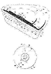
[0015] FIGURE 1 is a schematic diagram, with a portion shown in cross section
and a
portion shown in perspective view, of an illustrative embodiment of a system
for treating a
tissue site on a patient with reduced pressure;
[0016] FIGURE 2 is a schematic, cross-section of an illustrative embodiment of
a
system for treating a tissue site on a patient with reduced pressure;
[0017] FIGURE 3A is a schematic, top plan view of a portion of the system of
FIGURE 2;
[0018] FIGURE 3B is the portion of a reduced-pressure system shown in FIGURE
3A
with a leak shown;
[0019] FIGURE 4 is a schematic, top plan view of an illustrative embodiment of
a
sealing member and a leak-detection member; and
[0020] FIGURE .5 is a schematic, top plan view of an illustrative embodiment
of a
portion of a system for treating a tissue site on a patient with reduced
pressure.
6
CA 02844663 2014-02-06
WO 2013/039622 PCT/US2012/050314
DETAILED DESCRIPTION OF ILLUSTRATIVE EMBODIMENTS
[0021] In the following detailed description of the illustrative, non-limiting
embodiments, reference is made to the accompanying drawings that form a part
hereof. These
embodiments are described in sufficient detail to enable those skilled in the
art to practice the
invention, and it is understood that other embodiments may be utilized and
that logical
structural, mechanical, electrical, and chemical changes may be made without
departing from
the spirit or scope of the invention. To avoid detail not necessary to enable
those skilled in the
art to practice the embodiments described herein, the description may omit
certain information
known to those skilled in the art. The following detailed description is,
therefore, not to be
taken in a limiting sense, and the scope of the illustrative embodiments are
defined only by the
appended claims.
[0022] Referring now to the drawings and initially and primarily to FIGURE 1,
a
system 100 for treating a tissue site 102 on a patient 104 with reduced
pressure is presented
that includes a leak-detection member 106. The tissue site 102 may be, as a
non-limiting
example, an open wound 108 involving a patient's epidermis 110, deimis 112,
and possibly
subcutaneous tissue 114. In other examples, the tissue site 102 may be a
surface wound on the
patient's epidermis 110 or at another tissue site. The tissue site 102 may be
the bodily tissue
of any human, animal, or other organism, including bone tissue, adipose
tissue, muscle tissue,
dermal tissue, vascular tissue, connective tissue, cartilage, tendons,
ligaments, or any other
tissue. Treatment of the tissue site 102 may include the removal of fluids,
e.g., exudate or
ascites.
[0023] The system 100 includes a distribution manifold 116 for disposing
proximate to
the tissue site 102. The distribution manifold 116 has a first side 118 and a
second, tissue-
facing side 120. The distribution manifold 116 references a substance or
structure that is
provided to assist in applying reduced pressure to, delivering fluids to, or
removing fluids
from the tissue site 102. The distribution manifold 116 typically includes a
plurality of flow
channels or pathways that distribute fluids provided to and removed from the
tissue site 102
around the distribution manifold 116. In one illustrative embodiment, the flow
channels or
pathways are interconnected to improve distribution of fluids provided or
removed from the
tissue site 102. The distribution manifold 116 may be a biocompatible material
that is capable
7
CA 02844663 2014-02-06
WO 2013/039622
PCT/US2012/050314
of being placed in contact with the tissue site 102 and distributing reduced
pressure to the
tissue site 102. Examples of the distribution manifold 1 1 6 may include,
without limitation,
devices that have structural elements arranged to form flow channels, such as,
for example,
cellular foam, open-cell foam, porous tissue collections, liquids, gels, and
foams that include,
or cure to include, flow channels. The distribution manifold 116 may be porous
and may be
made from foam, gauze, felted mat, or any other material suited to a
particular biological
application. In one embodiment, the distribution manifold 116 is a porous foam
and includes a
plurality of interconnected cells or pores that act as flow channels. The
porous foam may be a
polyurethane, open-cell, reticulated foam such as GranuFoam0 material
manufactured by
Kinetic Concepts, Incorporated of San Antonio, Texas. In some situations, the
distribution
manifold 116 may also be used to distribute fluids such as medications,
antibacterials, growth
factors, and various solutions to the tissue site 102. Other layers may be
included in or on the
distribution manifold 116, such as absorptive materials. wicking materials,
hydrophobic
materials, and hydrophilic materials.
[0024] In one illustrative embodiment, the distribution manifold 116 may be
constructed from bioresorbable materials that do not have to be removed from a
patient's body
following use of the system 100. Suitable bioresorbable materials may include,
without
limitation, a polymeric blend of polylactic acid (PLA) and polyglycolic acid
(PGA). The
polymeric blend may also include without limitation polycarbonates,
polyfumarates, and
capralactones. The distribution manifold 116 may further serve as a scaffold
for new cell-
growth, or a scaffold material may be used in conjunction with the
distribution manifold 116
to promote cell-growth. A scaffold is a substance or structure used to enhance
or promote the
growth of cells or formation of tissue, such as a three-dimensional porous
structure that
provides a template for cell growth. Illustrative examples of scaffold
materials include
calcium phosphate, collagen, PLA/PGA, coral hydroxy apatites, carbonates, or
processed
allograft materials.
[0025] The system 100 also includes a first or lower sealing member 122 for
disposing
over the distribution manifold 116 and at least a portion of the intact
epidermis 110 of the
patient 104. The lower sealing member 122 creates a sealed space 123 that
contains the
distribution manifold 116. The lower sealing member 122 has a first side 124
and a second,
tissue-facing side 126. The lower sealing member 122 has at least a portion
that is
8
CA 02844663 2014-02-06
WO 2013/039622
PCT/US2012/050314
substantially transparent so that colors and color contrasts on the leak-
detection member 106
may be seen through the lower sealing member 122. The lower sealing member 122
is
typically a drape, but the lower sealing member 122 may be any material that
provides a fluid
seal under normal operating conditions. The lower sealing member 122 may, for
example, be
an impermeable or semi-pemieable, elastomeric material. As used herein,
elastomeric means
having the properties of an elastomer. Elastomeric generally refers to a
polymeric material
that has rubber-like properties. More specifically, most elastomers have
ultimate elongations
greater than 100% and a significant amount of resilience. The resilience of a
material refers to
the material's ability to recover from an elastic defoimation. Examples of
elastomers may
include, but are not limited to, natural rubbers, polyisoprene, styrene
butadiene rubber,
chloroprene rubber, polybutadiene, nitrile rubber, butyl rubber, ethylene
propylene rubber,
ethylene propylene diene monomer, chlorosulfonated polyethylene, polysulfide
rubber,
polyurethane (PU), EVA film, co-polyester, and silicones. Additional, specific
examples of
sealing member materials include a silicone drape, a 3M Tegaderin drape, or a
polyurethane
(PIT) drape such as one available from Avery Dennison Corporation of Pasadena,
California.
[0026] A first attachment device 128 may be used to hold the lower sealing
member
122 against the patient's epidermis 110 or another layer, such as a gasket or
additional sealing
member. The first attachment device 128 may take numerous foims. For example,
the first
attachment device 128 may be a medically acceptable, pressure-sensitive
adhesive that
extends about a periphery, a portion, or the entire lower sealing member 122.
As additional
examples, the attachment device 128 may be a double-sided drape tape, paste,
hydrocolloid,
hydro gel or other sealing devices or elements. The first attachment device
128 may also be a
sealing ring or other device. The first attachment device 128 is disposed on
the second, tissue-
facing side 126 of the lower sealing member 122. Before use, the first
attachment device 128
may be covered by a release liner (not shown).
[0027] A liquid receptor 130 is fluidly coupled to the tissue site 102 for
receiving and,
at least partially, retaining liquids. In the illustrative embodiment of
FIGURE 1, the liquid
receptor 130 is formed by an absorbent layer 132 and may also include a first
wicking layer
134 and a second wicking layer 136. The wicking layers 134, 136 sandwich the
absorbent
layer 132. The wicking layers 134, 136 are fluid peimeable and attract
liquids. The absorbent
layer 132 may, as a non-limiting example, be a layer of super absorbent
fibers. The absorbent
9
CA 02844663 2014-02-06
WO 2013/039622 PCT/US2012/050314
layer 132 may be fluidly coupled through apertures 138 to the lower sealing
member 122, the
first attachment device 128, and consequently to the tissue site 102.
[0028] An upper sealing member 139 may be coupled with a second attachment
device
143 to a portion of the lower sealing member 122. Thus, the lower sealing
member 122 and
upper sealing member 139 may sandwich the absorbent layer 132 and the wicking
layers 134,
136. The upper sealing member 139 may also be substantially transparent, at
least at portions,
so that contrasts on the leak-detection member 106 may be seen through the
upper sealing
member 139.
[0029] The system 100 also includes a reduced-pressure source 140 associated
with the
distribution manifold 116 for providing reduced pressure to the sealed space
123 and, in
particular, to the distribution manifold 116. While the reduced-pressure
source 140 may be
any device for supplying a reduced pressure, such as a vacuum pump, wall
suction, micro-
pump, or other source, in the illustrative embodiment of FIGURE 1, the reduced-
pressure
source 140 is a micro-pump 142 that is adjacent to the liquid receptor 130.
While the amount
and nature of reduced pressure applied to a tissue site will typically vary
according to the
application, the reduced pressure will typically be between -5 mm Hg and -500
mm Hg and
more typically between -75 mm Hg and -300 mm Hg.
[0030] The micro-pump 142 may be a piezoelectric pump that may be sandwiched
between two foam cushion layers 144, 146. The two foam cushion layers 144, 146
may
themselves be sandwiched between a lower ply 148 and an upper ply 150. The
lower ply 148
and upper ply 150 may be bonded at their peripheries. A first power unit 152
and a control
unit 154 may be positioned between the lower ply 148 and the upper ply 150 and
may be
coupled to the micro-pump 142 for powering and controlling the micro-pump 142.
The micro-
pump 142 may exhaust air through a plurality of apertures 156 in the upper ply
150. A central
aperture 158 may fluidly couple a lower pressure side or suction side of the
micro-pump 142
to the second wicking layer 136. Reduced pressure may thereby be delivered
through the
second wicking layer 136, absorbent layer 132, and apertures 138 to the sealed
space 123 and
ultimately to the tissue site 102.
[0031] The system 100 also includes the leak-detection member 106. The leak-
detection member 106 allows a user to identify leaks of air or certain gases
from an exterior
through a location where a substantially gas tight seal has not been formed
between the lower
CA 02844663 2014-02-06
WO 2013/039622 PCT/US2012/050314
sealing member 122 and the patient's epidermis 110. The leak-detection member
106 may be
sized and configured to substantially surround the distribution manifold 116.
The leak-
detection member 106 surrounds at least where reduced pressure enters the
sealed space 123.
The leak-detection member 106 may comprise a detection material that is
reactive to air,
including carbon dioxide and oxygen to develop a color contrast when a portion
is exposed to
air and a portion is not exposed to air.
[0032] The leak-detection member 106 may be a curved member that is disposed
around (substantially 360 degrees about) the tissue site 102 being treated or
around the
distribution manifold 116. If air leaks between the epidermis 110 and the
lower sealing
member 122, a color contrast will develop on a portion of a leak path where
the leak path
encounters the leak-detection member 106. The user may then visually identify
the leak
location since the leak location coincides with the color contrast. The user
may then seal the
leak. The leak may be sealed by rubbing on the lower sealing member 122 to
improve the seal
or by adding additional sealing members along an edge or periphery of the
lower sealing
member 122 where the air first enters.
[0033] The leak-detection member 106 is foimed from the detection material.
The
detection material may be an agent alone or combined with an adhesive. The
agent may
respond visually to the amount of oxygen (02), carbon dioxide (CO2), or other
gas present.
Thus, for example, if more oxygen or more carbon dioxide is present at one
location on the
leak-detection member 106 than at another location, as is the case with a leak
in which air
enters, a visual indication will be established in the folin of a color
contrast. The leak-
detection member 106 may allow leaks with low flow, e.g., as low as or less
than 0.2 ml/hour,
to be identified.
[0034] The leak-detection member 106 may substantially surround the tissue
site 102.
Thus, when a leak occurs in any direction, the leak may be identified. The
leak-detection
member 106 may be a single ring as shown in FIGURE 1 or a plurality of rings
or members or
other shapes as shown in FIGURES 2, 3, and 4. The leak-detection member 106
may also be
formed from curved segments that are spaced. The curved segments preferably
cover 360
degrees around the tissue site 102 so that a leak path in any direction may be
identified. In
another illustrative embodiment, the leak-detection member 106 may be a region
on the tissue-
11
CA 02844663 2014-02-06
WO 2013/039622 PCT/US2012/050314
facing side 126 of the lower sealing member 122 or may be concomitant with the
tissue-facing
side 126 of the lower sealing member 122 altogether.
[0035] In one illustrative embodiment, the detection material may be a
material that
changes color or reacts as the pH changes. Under normal atmospheric
conditions, e.g., with
normal levels of carbon dioxide, the pH of water will be about 5.7. (Carbon
dioxide requires
the presence of water to form a weak acid resulting in a pH drop; similarly,
ammonia requires
moisture to form a weak base). If carbon dioxide is used as a challenge gas,
which will be
explained further below, the pH will be lower (3 ¨ 4). In any event, the pH
will increase when
ammonia gas is detected and will decrease when carbon dioxide is detected. The
change in pH
results in a change in the color. Thus, as the pH changes in a location but
not in other
locations, the color changes and creates a color contrast. Detection materials
that respond as
such to pH changes include the following: litmus, bromocresol purple,
bromocresol blue,
azolitmin, methyl red, bromocresol green. The detection material may also be a
REDOX-
based dye that is sensitive to oxygen. Illustrative examples of REDOX-based
dyes that are
sensitive to oxygen include the following: methylene Blue (available from
Sigma), N-
phenylanthranilic acid (available from Acros Organics), or Neutral Red
(available from Fisher
Scientific).
[0036] As another illustrative detection material, titanium dioxide and
glycerol may be
used. A mixture of titanium dioxide, methylene blue and glycerol becomes a
colorimetric
indicator for oxygen after activation by UV. The titanium dioxide oxidizes the
glycerol (a
sacrificial electron donor), reduces the REDOX dye methylene blue to a
colorless form until,
on exposure to oxygen, the reduced methylene blue is oxidized back to its blue
color.
[0037] In one illustrative embodiment, the detection material may be a
ultraviolet
(UV) light sensitive ink. When exposed to UV, the ink becomes colorless and
sensitive to
oxygen such that a blue color forms under the influence of oxygen. Thus, the
leak path will
show a blue on a portion that is in contrast to the color on the non-leaking
portions. The non-
leaking portions starve the ink of oxygen and become colorless. Thus, the leak-
detection
member 106 may include such an ink and a detection tool, e.g., a UV light
tool, may he
activated to give off UV light and help identify any leak paths.
[0038] In another illustrative example, the detection material is a
phosphorescence
material that becomes more fluorescent or less fluorescent when exposed to
air. Thus, a user
CA 02844663 2014-02-06
WO 2013/039622
PCT/US2012/050314
may cause portions of the leak-detection member 106 to become fluorescent by
exposing the
leak-detection member 106 to a detection tool, e.g., UV light or Infrared
light tool. If a leak
exists, the gas in the air will cause the detection material to be more or
less fluorescent
depending on the specific material used.
[0039] In one illustrative embodiment, the detection material includes a
fluorescent
agent that will fluoresce in response to UV light or IR and that is disposed
on the tissue-facing
side 126 of the lower sealing member 122. The detection material will
fluoresce until the
fluorescent agent contacts moisture and salt that are common on the epidermis
110. Upon
coming into contact with the moisture and salt, the detection material will
discontinue to
fluoresce or not fluoresce with the same strength (fluorescence quenching). In
areas where no
such contact is made between the detection material and the epidermis 110, the
detection
material will continue to fluoresce. Thus, the user may observe a color
contrast in locations
where a leak is probably located, i.e., where the lower sealing member 122 is
not contacting
the epidermis 110.
[0040] In another illustrative embodiment, the leak-detection member 106
includes a
detection material that fluoresces under UV or IR even when in contact with
the epidermis
110. The detection material, however, experiences fluorescent quenching when
exposed to
oxygen. Thus, the leak path will fluoresce less and will have a color
contrast.
[0041] In another illustrative embodiment, the detection material is a
material that
responds to a challenge gas. A challenge gas is a gas presented on an outside
of the sealing
member. If a leak exists, the challenge gas is pulled into the leak path and
reacts with the
detection material. For example, after applying the system 100, the user may
spray the
challenge gas using a challenge gas distributor. The challenge gas is
typically heaver than air.
The challenge gas is sprayed onto the sealing member, and if a leak exists,
the challenge gas
will enter the leak path and cause the detection material to take on a color
contrast.
[0042] Continuing to refer primarily to FIGURE 1, in operation, the user
disposes the
distribution manifold 116 proximate to the tissue site 102 that is to be
treated. The user then
disposes the leak-detection member 106 around the tissue site 102 or
distribution manifold
116. "[he user disposes the lower sealing member 122 over the distribution
manifold 116 and
the leak-detection member 106. The leak-detection member 106 may already be
attached to
the second, tissue-facing side 126 of the lower sealing member 122 and may be
applied as an
13
CA 02844663 2014-02-06
WO 2013/039622 PCT/US2012/050314
aspect of disposing the lower sealing member 122 or may be disposed separately
on the
_________ patient's epidet [Ms 110. In one illustrative embodiment,
disposing the leak-detection member
106 may involve disposing a curved member formed from the detection material
onto the
epidermis 110 of the patient 104 outboard of the tissue site 102. In another
illustrative
embodiment, disposing the leak-detection member 106 around the distribution
manifold 116
may involve applying a liquid that comprises the detection material onto the
intact epidermis
110 of the patient 104 outboard of the tissue site 102.
[0043] Reduced pressure is then provided to the distribution manifold 116,
e.g., by
activating the micro-pump 142. After the system 100 operates for a period of
time, if any
leaks exist, air will be pulled into the leak path and the leak-detection
member 106 will
develop a color contrast as previously noted. The color contrast coincides
with a portion of
the leak path, and the user may use the visual cue to locate the leak. The
user may then seal
the leak by applying force or rubbing the leak path or by applying additional
sealing members
at an edge of the lower sealing member 122 proximate to the identified leak
path.
[0044] Referring now primarily to FIGURE 2, another illustrative embodiment of
the
system 100 for providing reduced pressure to the tissue site 102 on the
patient 104 is
presented. The system is analogous in many respects to the system 100 of
FIGURE 1. In this
embodiment, however, the reduced-pressure source 140 is an external reduced-
pressure source
141 and the liquid receptor 130 is a canister or other external fluid
reservoir 131.
[0045] The external reduced-pressure source 141 is fluidly coupled by a
reduced-
pressure delivery conduit 162 to a reduced-pressure interface 164. hi one
illustrative
embodiment, the reduced-pressure interface 164 is a T.R.A.C.(R) Pad or Sensa
T.R.A.C. Pad
available from KCI of San Antonio, Texas. The reduced-pressure interface 164
allows the
reduced pressure to be delivered to the distribution manifold 116.
[0046] In this illustrative embodiment, only the lower or first sealing member
122 is
used and the leak-detection member 106 includes two concentric members. The
concentric
members forming the leak-detection member 106 are shown best in FIGURES 3A-3B.
Because in this illustrative embodiment the lower sealing member 122 is
transparent, the
portions beneath (on the tissue-facing side) of the lower sealing member 122
are shown
without hidden lines. Other structural aspects of the system 100 of FIGURE 2
are analogous
to FIGURE 1 and are not further described.
14
CA 02844663 2014-02-06
WO 2013/039622
PCT/US2012/050314
[0047] Referring now primarily to FIGURE 3A, a portion of the system of FIGURE
2
is presented in plan view. In FIGURE 3A, either the system 100 has not been
activated or has
been activated but no leak has been detected. No leak is detected as shown by
the absence of
any color contrast on the leak-detection member 106. On the other hand, in
FIGURE 3B, a
leak path 166 is shown by color contrasts 168 on the leak-detection member
106. While
generally not visible (other than the color contrasts 168), the leak path 166
is shown with
broken lines beginning at an edge or periphery 170 and extending to the
distribution manifold
116 from where the leak flows into the reduced-pressure interface 164.
[0048] Application of the system 100 of FIGURES 2-3B is analogous to that
presented
for the system 100 of FIGURE 1. It should be noted that in the various
embodiments, the
leak-detection member 106 may take many forms. The leak-detection member may
be a
single ring, a single member of any shape, a plurality of concentric members
such as
concentric circles shown in FIGURES 3A-3B or concentric squares shown in
FIGURE 4, a
plurality of spaced curved segments, or any other arrangement that will allow
leak paths in any
direction to be detected.
[0049] Referring now primarily to FIGURE 4, an illustrative embodiment of the
lower
sealing member 122 and leak-detection member 106 are presented. In this
embodiment, the
reduced-pressure source 140 has not yet been applied. Visual indicia 172 may
be included on
the lower sealing member 122 to aid the user in centering the lower sealing
member 122 on
the tissue site.
[0050] Referring now primarily to FIGURE 5, a portion of an illustrative
embodiment
of a system 200 for treating a tissue site, e.g., tissue site 102 in FIGURE 1,
on a patient with
reduced pressure is presented. The system 200 is analogous in many respects to
the system of
FIGURE 1, and analogous parts have been indicated by indexing the reference
numerals by
100. The system 200 includes a distribution manifold 216 for disposing
proximate to the
tissue site. The system 200 also includes a sealing member 222 for disposing
over the
distribution manifold 216 and at least a portion of intact epidermis of the
patient. The sealing
member 222 has at least a portion that is substantially transparent to allow
viewing of color
contrasts. "[he sealing member 222 includes a film that is at least partially
covered on a tissue-
facing side with a hydrophilic adhesive 276. The hydrophilic adhesive 276 is
preferably in a
pattern that surrounds an entry point 278. The entry point 278 is where
reduced pressure
CA 02844663 2014-02-06
WO 2013/039622
PCT/US2012/050314
enters a sealed space formed by the sealing member 222. The entry point 278
may be, for
example, where a reduced-pressure interface 264 is fluidly coupled to the
sealed space. The
sealed space is analogous to the sealed space 123 in FIGURES 1 and 2. In the
illustrative
embodiment of FIGURE 5, the pattern of the hydrophilic adhesive 276 includes a
first ring
280 relatively near the entry point 278 and inboard of the peripheral edge of
the distribution
manifold 216 and a second ring 282 outboard of the distribution manifold 216.
[0051] The system 200 includes a reduced-pressure source that is not
explicitly shown
but is analogous to the external reduced-pressure source 141 of FIGURE 2. The
reduced
pressure source 141 is associated with the distribution manifold 216 for
providing reduced
pressure to the distribution manifold 216. Under the influence of reduced
pressure, fluid
exudate from the tissue site is brought into contact with the hydrophilic
adhesive 276 at
locations where reduced pressure is acting and is not brought into contact
with the hydrophilic
adhesive 276 at locations where reduced pressure is not acting. Thus, where a
leak path 266
appears, the reduced pressure will be dissipated and the exudate will not be
brought into
contact with the hydrophilic adhesive 276. Because the exudate has a color or
tint, the
locations on the patterned hydrophilic adhesive 276 where the leak exists will
present a color
contrast 268. As with the previous embodiments, the color contrast 268 shows
the location of
the leak path and the leak may be sealed.
[0052] Referring again to FIGURES 1-4, according to an illustrative non-
limiting
embodiment, the leak-detection member 106 may be a skin-preparation fluid or
included as an
aspect of a skin-preparation fluid. The skin-preparation fluid includes a
detection material that
develops a color contrast when a portion is exposed to air and a portion is
not exposed to air.
The skin-preparation fluid is applied at least around the tissue site. The
tissue site is
surrounded by the skin-preparation fluid. As a non-limiting example of the
skin-preparation
fluid, in addition to skin preparation liquids, a REDOX color dye or other dye
may be
included. The lower sealing member 122 is then applied as previously
described. If a leak
exists, the air contacting the detection material in the skin-preparation
fluid will create a color
contrast in the skin-preparation fluid and thereby indicate the location of
the leak. In another
illustrative embodiment, the skin-preparation fluid includes methylene blue
that is applied.
After applying other aspects of the system 100, the reduced pressure is
applied and the
portions of the skin-preparation fluid under the lower sealing member 122 with
a substantially
16
CA 02844663 2014-02-06
WO 2013/039622 PCT/US2012/050314
air tight seal become starved for oxygen and change colors to become clear.
Any portions
with a leak will, because of the air flow, remain blue and thereby indicate
the leak location.
[0053] According to another illustrative embodiment, the system 100 for
treating the
tissue site 102 on the patient 104 with reduced pressure includes the
distribution manifold 116
for disposing proximate to the tissue site 102 and the lower sealing member
122 for disposing
over the distribution manifold 116 and at least a portion of the intact
epidermis 110 of the
patient 104. The tissue-facing side 126 of the lower sealing member 122 is
covered at least
partially with a first agent. The lower sealing member 122 has at least a
portion that is
substantially transparent to allow viewing of color contrasts. The system 100
also includes the
reduced-pressure source 140 associated with the distribution manifold 116 for
providing
reduced pressure to the distribution manifold 116 and a skin-preparation
fluid.
[0054] The skin-preparation fluid includes a second agent. When the first
agent of the
sealing member and the second agent of the skin-preparation fluid combine,
they form a
contact color indicative of contact between the first agent and second agent.
In places where
they do not contact, the color does not change. Thus, in use, the user will be
able to see a
color contrast at places where the lower sealing member 122 and the skin-
preparation fluid on
the patient's epidermis 110 are not touching. Such locations are probable leak
locations and
may be sealed by applying force, e.g., rubbing the probable leak location, or
applying
additional sealing members at an edge near the probable leak location.
[0055] Although the present invention and its advantages have been disclosed
in the
context of certain illustrative embodiments, it should be understood that
various changes,
substitutions, permutations, and alterations can be made without departing
from the scope of
the invention as defined by the appended claims. It will be appreciated that
any feature that is
described in connection to any one embodiment may also be applicable to any
other
embodiment.
[0056] It will be understood that the benefits and advantages described above
may
relate to one embodiment or may relate to several embodiments. It will further
be understood
that reference to "an" item refers to one or more of those items.
[0057] The steps of the methods described herein may be carried out in any
suitable
order, or simultaneously where appropriate.
17
CA 02844663 2014-02-06
WO 2013/039622
PCT/US2012/050314
[0058] Where appropriate, aspects of any of the embodiments described above
may be
combined with aspects of any of the other embodiments described to form
further examples
having comparable or different properties and addressing the same or different
problems.
[0059] It will be understood that the above description of preferred
embodiments is
given by way of example only and that various modifications may be made by
those skilled in
the art. The above specification, examples and data provide a complete
description of the
structure and use of exemplary embodiments of the invention. Although various
embodiments
of the invention have been described above with a certain degree of
particularity, or with
reference to one or more individual embodiments, those skilled in the art
could make
numerous alterations to the disclosed embodiments without departing from the
scope of the
claims.
18