Note: Descriptions are shown in the official language in which they were submitted.
CA 02844693 2014-02-07
WO 2013/023147 PCT/US2012/050349
COMBUSTOR
Related Applications
This application claims priority to U.S. Provisional Application No.
61/522,412,
filed August 11, 2011, the entirety of which is incorporated herein by
reference.
Technical Field
The invention relates to a fuel burner and, in particular, relates to a
combustor
for a gas turbine engine or heating appliance that imparts a centrifugal force
upon
combustion air or a combination of air and fuel.
Background
Gas turbines, also referred to as jet engines, are rotary engines that extract
energy from a flow of combustion gas. They have an upstream compressor coupled
to
a downstream turbine with a combustion chamber in between. There are many
different variations of gas turbines, but they all use the same basic
principal.
Jet aircraft are usually powered by turbojet or turbofan engines. A turbojet
engine is a gas turbine engine that works by compressing air with an inlet and
a
compressor, mixing fuel with the compressed air, burning the mixture in the
combustor,
and then passing the hot, high pressure gas through a turbine and a nozzle.
The
compressor is powered by the turbine, which extracts energy from the expanding
gas
passing through it. The engine converts energy in the fuel to kinetic energy
in the
exhaust, producing thrust. All the air ingested by the inlet passes through
the
compressor, combustor, and turbine.
A turbofan engine is very similar to a turbojet except that it also contains a
fan
at the front of the compressor section. Like the compressor, the fan is also
powered by
the turbine section of the engine. Unlike the turbojet, some of the flow
accelerated by
the fan bypasses the combustor and is exhausted through a nozzle. The bypassed
flow
is at a lower velocity, but a higher mass, making thrust produced by the fan
more
efficient than thrust produced by the core. Turbofans are generally more
efficient than
turbojets at subsonic speeds, but they have a larger frontal area which
generates more
drag at higher speeds.
Turboprop engines are jet engine derivatives that extract work from the hot
exhaust jet to turn a rotating shaft, which is then used to spin a propeller
to produce
additional thrust. Turboprops generally have better performance than turbojets
or
CA 02844693 2014-02-07
WO 2013/023147 PCT/US2012/050349
-2-
additional thrust. Turboprops generally have better performance than turbojets
or
turbofans at low speeds where propeller efficiency is high, but become
increasingly
noisy and inefficient at high speeds.
Turboshaft engines are very similar to turboprops, differing in that nearly
all of
the energy in the exhaust is extracted to spin the rotating shaft. Turboshaft
engines are
used for stationary power generating plants as well as other applications.
One problem associated with gas turbine engines, especially in aircraft, is
the
possibility of flame-out, which occurs when the flame becomes extinguished
within the
combustion chamber. One of the causes of flame-out is instability of the flame
front
within the combustor. Since engine failure during flight is clearly
problematic, it
would be advantageous to construct a gas turbine engine such that the
possibility of
flame-out was reduced. For stationary power generating systems there is a need
for
reduced emissions, primarily NOx, in order to meet newer, more stringent clean
air
requirements.
Summary of the Invention
The present invention provides a new and improved method of combustion and
a combustor or burner that can be used in a jet engine, as well as other
heating/burner
applications. In the illustrated embodiment, the combustor is shown as it
would be
used with a jet engine of the type that includes a compressor portion and a
turbine
portion.
According to one of the preferred and illustrated embodiments, the jet engine
includes a compressor portion and turbine portion. In this one preferred and
illustrated
embodiment, the combustor includes a longitudinally extending tube having a
central
axis, which is positioned to receive air that is charged by the compressor
portion. The
=
outer tube has an outer surface and an inner surface. An inner tube is
positioned within
the outer tube and includes an associated outer surface that is spaced from
the inner
surface of the outer tube, thereby defining a passage that may be a combustion
chamber
where a fuel mixture can be at least partially combusted.
In the illustrated embodiment, the outer tube includes fluid directing
structure
for communicating at least some of the air discharged by the compressor
portion to a
combustion chamber passage that is defined between the inner surface of the
outer tube
and the outer surface of the inner tube. The fluid directing structure directs
air in a
CA 02844693 2014-02-07
WO 2013/023147 PCT/US2012/050349
-3-
direction offset from the central axis of the outer tube, thereby causing
rotation of the
air about the central axis. At least one fuel supply member directly or
indirectly
supplies fuel to the combustion chamber passage in order to form a rotating or
swirling
fuel air mixture in the combustion chamber passage.
According to the invention, the rotating fuel mixture in the combustion
chamber
passage may be completely or partially burned in the combustion chamber
passage.
In a preferred and illustrated embodiment, the inner tube also includes
associated fluid directing structure for communicating air it receives from
the
compressor portion to the combustion chamber passage. The associated fluid
directing
structure directs the air in a direction that is also offset from the central
axis.
In one embodiment, the fuel member communicates directly with the
combustion chamber passage and directly supplies fuel to the chamber passage
where it
is mixed with the compressor air to form a rotating/swirling combustible
fuel/air
mixture. In an alternate embodiment, the fuel member premixes the fuel with
some
compressor air and then supplies the premixed fuel and air to the combustion
chamber
passage where it is mixed with the rotating compressor air (or fuel/air
mixture) already
delivered to the combustion chamber passage. In another alternative
embodiment, the
fuel member discharges fuel into a stream of air discharged by the compressor
portion
as it flows towards the combustor. In this alternate embodiment, both fuel and
compressor air flow through the fluid directing structure of the outer and/or
inner tubes
into the combustion chamber passage.
According to one illustrated embodiment, the outer and inner tubes are
arranged
such that their respective axes are coincident. According to an alternate
construction of
this embodiment, the axes of the inner and outer tubes are coincident with a
rotation
axis defined by the compressor portion.
According to a preferred embodiment, the fluid directing structure includes a
plurality of openings and a guide associated with each opening, the guides
being angled
relative to a tube surface for imparting a radial rotation to the air about
the central axis.
In the illustrated embodiment, the guides are arranged in a series of rows
that extend
around the periphery of the outer tube. In the preferred embodiment, the inner
tube has
a similar fluid directing structure.
CA 02844693 2014-02-07
WO 2013/023147 PCT/US2012/050349
-4--
In a more preferred embodiment, the fluid directing structure includes a
series
of steps formed in the outer tube, the steps including openings for directing
the air into
the combustion chamber passage in a direction that causes rotation or swirling
of the
mixture radially about the central axis. According to a feature of this more
preferred
embodiment, each step has an L-shape including a first member and a second
member
including the openings for directing the air, such that the openings of one
step direct the
air across the adjoining step to impart rotation to the mixture.
According to an exemplary embodiment, the fluid directing structure includes a
plurality of openings that each extend from the outer surface of the outer
tube to the
inner surface, each opening extending through the outer tube at a relative
angle to an
axis extending normal to the outer surface of the inner tube and through the
central
axis. According to a feature of this embodiment, the outer tube includes a
plurality of
second openings that each extend from the outer surface of the outer tube to
the inner
surface in a direction extending to the central axis. In a more preferred
embodiment,
the inner tube includes similar fluid directing structure.
In a preferred and illustrated embodiment, the outer tube is formed as a
series of
overlapping arcuate plates that define the fluid directing structure, each
plate having a
corrugated profile and having a series of passages through which the air is
directed into
the combustion chamber passage. In this embodiment, the corrugated profile
includes a
plurality of alternating peaks and valleys and, preferably, the overlapping
plates are
longitudinally and radially offset from one another, such that the peaks of
one plate are
positioned between the peaks of adjacent plates. In addition, in this
embodiment, each
plate directs the air in a direction that extends substantially parallel to
the adjoining
plate to impart rotation to the mixture.
In the preferred construction of this embodiment, the inner tube of the
combustor includes a first end that communicates with air discharged by the
compressor portion and a second end having an end wall for closing the second
end of
the inner tube in a gas tight manner. With this construction, the fluid
directing structure
associated with the inner and outer tubes provides the only fluid path to the
combustion
chamber passage.
CA 02844693 2014-02-07
WO 2013/023147
PCT/US2012/050349
-5-
In a combustor constructed in accordance with one or more of the disclosed
embodiments, the rotating mixture is radially layered within the combustion
chamber
passage.
According to still another embodiment of the invention, the combustor includes
a tube having a central axis that is located intermediate the compressor
portion and the
turbine portion and has an outer and inner surface. Fluid directing structure
is formed
on the tube, including passages extending from the outer surface to the inner
surface.
The inner surface of the tube defines a combustion chamber. A passage
communicates
air discharged by the compressor portion with the outer surface of the tube.
The fluid
directing structure directs the compressor air at an angle offset from the
central axis of
the tube, thereby causing rotation of compressor air in the combustion
chamber. A fuel
member supplies fuel or a mixture of fuel and air, directly or indirectly, to
the
combustion chamber.
In the illustrated combustion of this alternate embodiment, a spaced apart
continuous wall surrounds the tube, thereby defining at least a portion of the
passage
for communicating air to the outer surface of the tube. In a more preferred
construction
of this embodiment, the jet engine includes a plurality of these alternate
combustors
that are spatially arranged around an axis of rotation defined by the
compressor portion.
An object of the present invention is to provide a jet engine combustor in
which
air or fuel and air are forced through fluid directing structures to cause
swirling and/or
rotation of the air/fuel mixture about the axis of the combustor.
Other objects and advantages and a fuller understanding of the invention will
be
had from the following detailed description of the preferred embodiments and
the
accompanying drawings.
Additional features and a further understanding of the invention will become
apparent by reading the following detailed description made in connection with
the
accompanying drawings.
Brief Description of the Drawing.s,
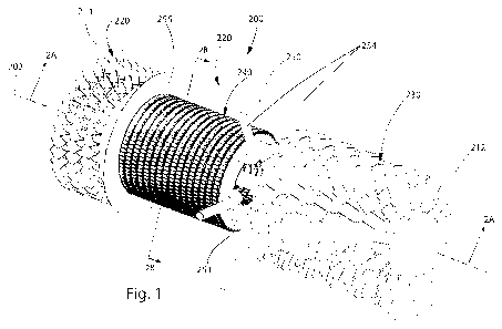
Fig. 1 is a schematic illustration of a combustor for use in a jet engine in
accordance with an aspect of the present invention;
Fig. 2A is a section view taken along line 2A-2A of Fig. 1;
Fig. 2B is a section view taken along line 2B-2B of Fig. 1;
CA 02844693 2014-02-07
WO 2013/023147 PCT/US2012/050349
-6-
Fig. 3A is an enlarged view of a portion of a fluid directing structure
constructed in accordance with a preferred embodiment of the invention;
Fig. 3B is a section view of Fig. 3A taken along line 3B-3B;
Figs. 4A-4D are enlarged views of portions of alternative fluid directing
structure in accordance with the present invention;
Fig. 5 is a schematic illustration of an alternative combustor for use in a
jet
engine in accordance with another aspect of the present invention;
Fig. 6A is a section view taken along line 6A-6A of Fig. 5;
Fig. 7 is a schematic illustration of an alternative combustor for use in a
jet
engine in accordance with another aspect of the present invention;
Fig. 8A is a section view taken along line 8A-8A of Fig. 7;
Fig. 8B is a section view taken along line 8B-8B of Fig. 7;
Fig. 9 is a schematic illustration of an alternative combustor for use in a
jet
engine in accordance with another aspect of the present invention;
Fig. 10 is a section view taken along line 10-10 of Fig. 9, and;
Fig. 11 is a section view taken along line 11-11 of Fig. 10.
Detailed Description
The invention relates to a fuel burner and, in particular, relates to a
combustor
for a gas turbine engine that imparts a centrifugal force upon combustion air
or a
combination of air and fuel. Although the drawings generally depict a turbojet
type
engine and the specification describes the present invention in use in a jet
engine, those
having ordinary skill will appreciate that the combustor of the present
invention
described herein is suitable for use in any of the engine variants described
above.
Figs. 1-2B illustrate a combustor 240 for use in a jet engine 200 in
accordance
with an embodiment of the present invention. As shown in Fig. 1, the jet
engine 200
extends along an axis 202 and includes a housing 210 that extends along the
axis from a
first end 212 to a second end 214. A wall 216 of the housing 210 defines an
interior
passage 218 that extends the length of the housing. A turbine 220, a
compressor 230,
and at least one combustor 240 are positioned within the passage 218 of the
housing
210 and along the axis 202. The compressor 230 includes a shaft or connecting
member 232 that connects the compressor to the turbine 220 such that the
connecting
CA 02844693 2014-02-07
WO 2013/023147 PCT/US2012/050349
-7-
member and turbine rotate together. The combustor 240 is positioned axially
between
the turbine 220 and the compressor 230.
As shown in Figs. 2A-2B, the combustor 240 includes outer and inner tubes
242, 244 that are concentric to one another about a central axis 241 and
secured to one
another and the housing 210. The central axis 241 of the combustor 240 may be
coaxial with the axis 202 of the engine 202 or may be spaced from the axis of
the
engine (not shown). The connecting member 232 extends through the inner tube
244
and a shaft seal 233 is provided between the connecting member and the inner
tube to
prevent fluid from passing between the connecting member and the inner tube
directly
into the turbine 220.
The space between the outer and inner tubes 242, 244 defines a fluid
passage 274 for receiving fuel and air. The periphery of the outer tube 242
includes
fluid directing structure 248 for directing fluid radially inward to the fluid
passage 274.
More specifically, the fluid directing structure 248 is configured to direct
fluid to the
fluid passage 274 in a direction that is offset from the central axis 241 of
the combustor
240 and along a path that is angled relative to the normal of the inner
surface (not
shown) of the outer tube 242.
The periphery of the inner tube 244 includes fluid directing structure 252 for
directing fluid from the interior 250 of the inner tube radially outward into
the fluid
passage 274. More specifically, the fluid directing structure 252 is
configured to direct
fluid into the fluid passage 274 in a direction that is offset from the
central axis 241 of
the combustor 240 and along a path that is angled relative to the normal of
the outer
surface (not shown) of the inner tube 244. The fluid directing structures 248,
252 may
direct their respective fluid in the same general direction. The fluid
directing structure
248, 252 may include a series of openings with associated fins or guides for
directing
the fluid in the desired manner (Figs. 3A-4D).
The jet engine 200 further includes one or more tubular fuel supply members
254 that extend into or are otherwise in direct fluid communication with the
fluid
passage 274 of the combustor 240 and extend radially outward from the passage,
through the wall 216 of the housing 210, and to a fuel source (not shown)
outside of the
housing. The fuel supply members 254 thereby deliver fuel directly to the
fluid
passage 274, as indicated generally by arrows Fl. Although six fuel supply
members
CA 02844693 2014-02-07
WO 2013/023147 PCT/US2012/050349
-8-
254 spaced radially equidistant from one another are illustrated in Figs. 1-
2B, it will be
appreciated that any number of fuel supply members exhibiting any spacing
configuration may be provided in accordance with the present invention.
A ring-shaped wall 251 (see Fig. 2B) is secured to the end of the outer and
inner
tubes 242, 244 closer to the compressor 230 in order to seal one end of the
fluid
passage 274 in a fluid-tight manner. The wall 251 is provided with openings
253 that
receive ends of the fuel supply members 254 to establish the direct fluid path
between
the fuel supply members and the fluid passage 274.
In operation, air enters the compressor 230 at the first end 212 of the
housing
210 in the direction indicated generally by the arrows D2 (Fig. 2A) and exits
the
compressor as compressed air. Some of the compressed air exiting the
compressor 230
flows directly into the interior 250 of the inner tube 244 as indicated
generally by the
arrows D3 and through the fluid directing structure 252 in the inner tube 244
into the
fluid passage 274. Some of the compressed air also flows to the peripheral
annular
space 277 between the outer tube 242 and the wall 216 of the housing 212,
where it
flows through the fluid directing structure 248 in the outer tube and into the
fluid
passage 274 as indicated generally by arrows D4. A wall 255 secured to the end
of the
outer and inner tubes 242, 244 closer to the turbine 220 and between the outer
tube and
the wall 216 of the housing 210 prevents the compressed air D4 from passing
into the
turbine without first passing through the combustor 240.
The compressed air D3, D4 is mixed with fuel Fl that is injected into the
combustor 240 via the fuel supply members 254. Since the ring-shaped wall 251
blocks the end of the fluid passage 274 adjacent to the compressor 230, the
fuel Fl is
directed by the fuel supply members 254 directly into the fluid passage 274.
Accordingly, the fluid directing structures 248, 252 of the combustor 240 only
control
the flow of compressed air D4, D3 into the fluid passage 274 such that the
compressed
air mixes with the fuel Fl from the fuel supply members 254 within the fluid
passage
274 in a desired manner. More specifically, as the peripheral air D4 passes
through the
fluid directing structure 248 in the outer tube 242 and into the fluid passage
274, the air
mixes with the fuel Fl exiting the fuel supply members 254. Due to the
configuration
of the fluid directing structure 248, the compressed air D4 is imparted with a
centrifugal force about the central axis 241 of the combustor 240 as it enters
the fluid
CA 02844693 2014-02-07
WO 2013/023147 PCT/US2012/050349
-9-
passage 274. The swirling air D4 mixes with the fuel Fl to create a swirling
air/fuel
mixture within the fluid passage 274 and about the central axis 241 of the
combustor
240.
Likewise, the compressed air D3 enters the interior 250 of the inner tube 244
and passes through the fuel directing structure 252 of the inner tube 244 and
into the
fluid passage 274, thereby imparting a centrifugal force upon the compressed
air D3
about the central axis 241 of the combustor 240. The swirling air D3 mixes
with the
fuel Fl to create an additional swirling air/fuel mixture within the fluid
passage 274 and
about the central axis 241 of the combustor 240. The mixture formed from the
fuel Fl
and the compressed air D3 mixes with and becomes indistinguishable from the
mixture
fo -flied from the fuel Fl and the compressed air D4 within the fluid passage
274.
Since the fluid directing structures 248, 252 extend around the entire
periphery
of the outer tube 242 and the inner tube 244, respectively, the collective
air/fuel mixture
within the fluid passage 274 is forced generally in a single direction,
indicated by arrow
R (Fig. 2B), that is transverse to the central axis 241 of the combustor 240.
It will be
appreciated that the fluid directing structures 248, 252 may direct the
respective air/fuel
mixtures in the same direction, e.g., clockwise relative to the central axis
241, within
the fluid passage 274. Consequently, the air/fuel mixture within the fluid
passage 274
undergoes a rotational, spiraling effect relative to the central axis 241 of
the combustor
240 and within the fluid passage 274. The rotating, spiraling air/fuel mixture
is ignited
by an ignition device (not shown) of any number of types well known in the art
and
positioned in any number of suitable locations to light the combustor 240. For
example, the wall 251 may be provided with an opening (not shown) through
which an
igniter extends. Flame proving means (not shown) may be positioned in any
number of
suitable locations to detect the presence of flame.
Due to the continued supply of air and fuel to the combustor 240 from the
compressor 230 and the fuel supply members 254, subsequent spiraling air/fuel
mixtures are created within the fluid passage 274 prior to complete combustion
of prior
air/fuel mixtures within the passage such that the spiraling air/fuel mixtures
become
radially layered within the fluid passage. The swirling or rotation of the air
fuel
mixture in the passage 274 provides thorough mixing of the fuel and air,
thereby
CA 02844693 2014-02-07
WO 2013/023147 PCT/US2012/050349
-10-
improving combustion. The swirling pattern imparted to the fuel air mixture
contributes to combustion stability and, therefore, reduces the chances of
flame out.
As shown in Figs. 2A-2B, the combustion products from the ignited air/fuel
mixture exit the combustor 240 rotating about the central axis 241 of the
combustor 240
and the axis 202 of the jet engine 200 as indicated generally by arrows R2.
The
combustion products of the air/fuel mixture exit the combustor 240 at elevated
pressure
and velocity and pass through the turbine 220, thereby imparting rotation upon
the
turbine as indicated generally by arrow R3. The turbine 220, in turn, directs
the
combustion products out of the jet engine 200 in the direction indicated
generally by
arrows T to provide thrust to the aircraft. Since the connecting member 232
rotatably
connects the turbine 220 to the compressor 230, the rotating turbine drives
the
compressor.
Each of the fluid directing structures 248, 252 may have any configuration
suitable for imparting rotation to the compressed air D4, D3, respectively, to
form an
air/fuel mixture with the fuel Fl and within the fluid passage 274 that swirls
about the
central axis 241 of the combustor 240 in accordance with the present
invention. Figs.
3A-3B illustrate one configuration of the fluid directing structure 252 of the
inner tube
244 and those having ordinary skill will appreciate that the fluid directing
structure 248
of the outer tube 242 may have a similar construction to the fluid directing
structure
252. Alternatively, the fluid directing structures 248 and 252 may be
dissimilar (not
shown). In any case, the fluid directing structure 248 is configured to direct
fluid
radially inward while the fluid directing structure 252 is configured to
direct fluid
radially outward.
As shown in Figs. 3A-B, the fluid directing structure 252 includes a plurality
of
openings 284 in the inner tube 244 for allowing the compressed air D3 to pass
radially
outward from the central passage 250 of the inner tube to the fluid passage
274. Each
of the openings 284 extends entirely through the inner tube 244 from an inner
surface
282 to an outer surface 280. Each opening 284 may have any shape, such as
rectangular, square, circular, triangular, etc. The openings 284 may all have
the same
shape or different shapes. The openings 284 are aligned with one another along
the
periphery, i.e., around the circumference, of the inner tube 244 to form an
endless loop.
One or more endless loops of openings 284 may be positioned adjacent to one
another
CA 02844693 2014-02-07
WO 2013/023147 PCT/US2012/050349
-11-
or spaced from one another along the length of the inner tube 244. Each loop
may have
any number of openings 284. The openings 284 in adjacent loops may be aligned
with
one another or may be offset from one another. The size, shape, configuration,
and
alignment of the openings 284 in the inner tube 244 is dictated by desired
flow and
performance characteristics of the compressed air D3 flowing through the
openings.
Although the openings 284 are illustrated as being arranged in a predetermined
pattern
along the inner tube 244, it will be appreciated that the openings may be
randomly
positioned along the inner tube (not shown).
Each opening 284 includes a corresponding fluid directing projection or guide
286 for directing the compressed air D3 passing through the associated opening
radially
outward into the fluid passage 274 and in a direction that is offset from the
central axis
241 of the combustor 240, i.e., a direction that will not intersect the
central axis. The
guides 286 are formed on or integrally attached to the inner surface 282
and/or the
outer surface 280 (not shown) of the inner tube 244. Each guide 286 extends at
an
angle (shown in Fig. 3b) relative to the outer surface 280 of the inner tube
244. The
guides 286 may extend at the same angle or at different angles relative to the
outer
surface 280 of the inner tube 244. Each guide 286 extends at an angle,
indicated at a2,
relative to an axis 287 extending normal to the outer surface 280 of the inner
tube 244.
Since the fluid directing structure 248 on the outer tube 242 may be formed
similar to the fluid directing structure 252 on the inner tube 244, those
having ordinary
skill in the art will appreciate that guides and openings associated with the
fluid
directing structure 248 (not shown) direct the compressed air D4 passing
through the
outer tube radially inward toward the central passage 274 and in a direction
that is
offset from the central axis 241 of the combustor 240. Similar to the fluid
directing
structure 252 on the inner tube 244, the guides of the fluid directing
structure 248 on
the outer tube 242 may be formed in or integrally attached to the inner
surface and/or
the outer surface of the outer tube (not shown). In the illustrated
embodiment, the fluid
directing structures 248, 252 direct the associated incoming compressed air
D4, D3 in
the same general direction such that the combined air/fuel mixture swirls
within the
fluid passage 274 around the central axis 241 of the combustor 240 in the same
general
direction.
CA 02844693 2014-02-07
WO 2013/023147 PCT/US2012/050349
-12-
Figs. 4A-D illustrate alternative configurations of the fluid directing
structure
252 in the inner tube 244 in accordance with the present invention. The fluid
directing
structure 252a-d directs the incoming compressed air D3 radially outward into
the fluid
passage 274 and in a direction that is 1) offset from the central axis 241 and
2) angled
relative to the normal of the outer surface 280 of the inner tube 244 such
that
compressed air mixes with the fuel Fl to form an air/fuel mixture within the
central
passage 274 that exhibits a swirling, rotational path around the central axis
while
becoming radially layered relative to the central axis. The openings in the
fluid
directing structure may be randomly positioned along the inner tube 244 or may
be
arranged in any predetermined pattern dictated by desired flow and performance
criterion.
Figs. 4A-D illustrate alternative configurations of the fluid directing
structure
252, 248 that may be formed on or integrally attached to the inner and/or
outer surface
of the respective tube 244, 242 in accordance with the present invention. More
specifically, either of the fluid directing structures 248, 252 may exhibit
any of the
configurations shown in Figs. 4A-D. In the preferred embodiment, the fluid
directing
structure 248 directs the incoming compressed air D4 radially inward into the
fluid
passage 274 and in a direction that is 1) offset from the central axis 241 and
2) angled
relative to the normal of the inner surface of the outer tube 242 (not shown)
such that
the compressed air mixes with the fuel Fl to foim an air/fuel mixture that
exhibits a
swirling, rotational path within the central passage 274 and around the
central axis.
Likewise, the fluid directing structure 252 directs the incoming compressed
air D3
radially outward into the fluid passage 274 and in a direction that is 1)
offset from the
central axis 241 and 2) angled relative to the normal of the outer surface 280
of the
inner tube 244 (not shown) such that compressed air mixes with the fuel Fl to
form an
air/fuel mixture that exhibits a swirling, rotational path within the central
passage 274
and around the central axis. In each ease, the openings in the fluid directing
structure
248, 252 may be randomly positioned along the respective tube 242, 244 or may
be
arranged in any predetermined pattern dictated by desired flow and performance
criterion.
In Fig. 4A, the fluid directing structure 252a includes a plurality of guides
286a
that define openings 284a in the inner tube 244a. The guides 286a are arranged
in a
CA 02844693 2014-02-07
WO 2013/023147
PCT/US2012/050349
-13-
series of rows that extend around the periphery of the inner tube 244a. The
annular
rows are positioned next to one another along the length of the inner tube
244a. The
guides 286a of adjacent rows may be radially offset from one another or may be
radially aligned with one another (not shown). The guides 286a in each row may
be
similar or dissimilar to one another. The guides 286a direct the compressed
air D3
passing through the openings 284a in a radially inward direction that is
offset from the
central axis 241 and at an angle (12 relative to the axis 287a extending
normal to the
outer surface 280a of the inner tube 244a. If the guides 286a within a row are
fully or
partially aligned with one another around the periphery of the inner tube
244a, the
compressed air D3 exiting each guide in that row is further guided in a
direction offset
from the central axis 241 by the adjacent guide(s) in the same row.
In Fig. 4B, the inner tube 244b is formed as a series of steps that each
includes a
first member 283 and a second member 285 that extends substantially
perpendicular to
the first member to form an L-shaped step. The second member 285 of each step
includes a plurality of openings 284b for directing the compressed air D3 in a
direction
that is offset from the central axis 241 and angled relative to the axis (not
shown)
extending normal to the outer surface 280b of the inner tube 244b. In
particular, the
openings 284b in each second member 285 direct the compressed air D3 across
the first
member 283 of the adjoining step to impart rotation to the compressed air and,
thus, to
the air/fuel mixture within the fluid passage 274 about the central axis 241.
In Fig. 4C, the fluid directing structure 252c includes a plurality of
openings
284c that extend from the inner surface 282c of the inner tube 244c to the
outer surface
280c. The openings 284c extend through the inner tube 244c at an angle
relative to the
axis 287c extending normal to the outer surface 280c of the inner tube 244c
and
through the central axis 241 of the combustor 240. The openings 284c in the
inner tube
244c direct the compressed air D3 and, thus, the air/fuel mixture within the
fluid
passage 274 in a direction that is offset from the central axis 241 and at an
angle
relative to the axis 287c in order to impart rotation to the air/fuel mixture
within the
fluid passage about the central axis.
In Fig. 4D, the fluid directing structure 252d is formed by a series of
arcuate,
overlapping plates 330 that cooperate to form the inner tube 244d. Each plate
330 has a
corrugated profile that includes peaks 332 and valleys 334. The plates 330 are
CA 02844693 2014-02-07
WO 2013/023147
PCT/US2012/050349
-14-
longitudinally and radially offset from one another such that that peaks 332
of one plate
330 are spaced between the peaks of adjacent plates. In this configuration,
the peaks
332 and valleys 334 of the plates create passages 336 through which the
compressed air
D3 is directed. Each plate 330 directs the compressed air D3 in a direction
that extends
substantially parallel to the adjoining arcuate plate to impart rotation to
the compressed
air and, thus, to the air/fuel mixture within the fluid passage 274 about the
central axis
241. The air/fuel mixture within the fluid passage 274 is thereby directed in
a direction
that is offset from the central axis 241 of the combustor 240 and angled
relative to the
axis (not shown) extending normal to the plates 330.
Figs. 5-6A illustrate a jet engine 200a in accordance with another embodiment
of the present invention. Features in Figs. 5-6A that are identical to
features in Figs. 1-
2B have the same reference number as Figs. I-2B, whereas features in Figs. 5-
6A that
are not similar to features in Figs. 1-2B are given the suffix "a". Figs. 5-6A
illustrate a
jet engine 200a similar to the jet engine 200 of Figs. 1-2B. In the jet engine
200a of
Figs. 5-6A, the fuel being delivered via the fuel pipe 254a is partially mixed
with air
prior to being injected into the region 274. The partially pre-mixed fuel is
indicated by
the reference character F3 and, as seen best in Fig. 6A, the fuel pipe 254a
passes
through a pre-mix chamber 254'. As seen best in Fig. 6A, the pre-mix chamber
254'
receives compressor air indicated by the reference character D5 through a port
(not
specifically shown) formed in the pre-mix chamber 254'. Fuel passing through
the
chamber mixes with the incoming air stream (D5) and is injected to the region
274
where it is mixed with additional air D4, D3 delivered through ports 252, 248
formed in
the members 244, 242, respectively (see also Fig. 2B).
The jet engine burner shown in Fig. 6A operates essentially similar to the
burner
shown in Fig. 2A, except that the fuel is pre-mixed with some air prior to
being injected
into the region 274. The fuel and air movement patterns shown in Fig. 2B are
equally
applicable to the burner shown in Fig. 6A. In the jet engine 200a of Figs. 5-
6A,
however, the fuel delivered by the fuel supply members 254a is partially pre-
mixed
with the incoming compressed air D5 before being discharged into the chamber
274.
This partial fuel mixture is further mixed with compressed air D3 and D4 which
is
injected through the respective fluid directing structure 252 and 248 and into
the fluid
CA 02844693 2014-02-07
WO 2013/023147 PCT/US2012/050349
-15-
passage/combustion chamber 274' where the fully mixed fuel charge is ignited
and
burned.
The fluid directing structure 252 allows the air D3 within the passage 250 to
be
directed radially outward into the fluid passage 274, and the fluid directing
structure
248 allows the air D4 in the region 277 outside of the outer tube 242 to be
directed
radially inward into the fluid passage 274. Either or both of the fluid
directing
structures 248, 252 may have any of the configurations illustrated in Figs. 3A-
4D.
The compressed air D3, D4 mixes with the partial fuel mixture F3 from the fuel
supply members 254a to form an air/fuel mixture within the fluid passage 274
that
swirls around the axis 241 of the combustor 240a. Due to the configuration of
the fluid
directing structure 248, the compressed air D4 is imparted with a centrifugal
force
about the axis 241 of the combustor 240a as it passes into the fluid passage
274.
Likewise, the compressed air D3 enters the interior 250 of the inner tube 244
and then
through the directing structure 252 of the inner tube 244 and into the fluid
passage 274,
thereby imparting a centrifugal force upon the air/fuel mixture about the axis
241 of the
combustor 240a.
Those having ordinary skill in the art will appreciate that a mixture of air
and
fuel is formed in the fluid passage and imparted with a centrifugal force that
causes the
air/fuel mixture within the fluid passage 274 to rotate or spiral around the
central axis
of the combustor, thus improving and stabilizing combustion.
Figs. 7-8 illustrate a jet engine 200b in accordance with another embodiment
of
the present invention. Features in Figs. 7-8 that are identical to features in
Figs. 1-2B
or Figs. 5-6A have the same reference number as Figs. 1-2B or Figs. 5-6A,
whereas
features in Figs. 7-8 that are not similar to features in Figs. 1-2B are given
the suffix
"b". Similar to the jet engine 200 of Figs. 1-2B, a wall 251b is secured to
the end of the
combustor 240b closer to the compressor 230 and a wall 255b is secured to the
end of
the combustor closer to the turbine 220. In the jet engine 200b of Figs. 7-8,
however,
the fuel F4 is injected upstream from the combustor and is completely mixed
with
compressed air D4' before entering the combustor 240b.
The jet engine 200b of Figs. 7-8 includes a fluid mixing element 290 secured
to
the housing 210 for pre-mixing the compressed air D4' and fuel F4 exiting the
fuel
supply members 254b such that the air and fuel is completely mixed prior to
entering
CA 02844693 2014-02-07
WO 2013/023147 PCT/US2012/050349
-16-
the combustor 240b. The fluid mixing element 290 is positioned along the axis
202 of
the jet engine 200b between the fuel supply members 254b and the combustor
240b and
includes an outer element 292 and an inner element 294 positioned concentric
to one
another and the connecting member 232. The outer element 292 is ring-shaped
and has
a generally frustoconical configuration that tapers radially inward in a
direction
extending towards the combustor 240b, i.e., leftward as viewed in Fig. 8. The
inner
element 294 is positioned in the interior of the outer element 292 and is
secured to or
integrally formed with the outer element. The compressor/turbine connecting
member
232 extends through an opening indicated generally by the reference character
294a in
the inner element 294.
An annular gap 296 extends between the inner element 294 and the outer
element 292 and tapers inwardly in a direction extending towards the combustor
240b,
i.e., the cross-sectional area of the gap along the axis 202 decreases in the
direction
towards the combustor. The fluid mixing element 290 is configured such that
the
compressed air D4' from the compressor and the fuel F4 exiting the fuel supply
members 254b must pass through the gap 296 in the mixing element in order to
reach
the combustor 240b. Since the cross-sectional area of the gap 296 decreases
along the
length of the fluid mixing element 290, the compressed air D4' and fuel F4
become
mixed together as the air and fuel travel through the fluid mixing element.
The air D4'
and fuel F4 exit the fluid mixing element 290 as a fully pre-mixed mixture,
indicated
generally as M in Fig. 8. Although the fluid mixing element 290 is illustrated
as having
a particular construction, those having ordinary skill will appreciate that
any structure
or structures may be used that are configured to mix the compressed air D4'
and fuel F4
to form a fully pre-mixed mixture M that enters the combustor 240b to be
ignited.
The mixture M enters the combustor 240b along two different pathways. Some
of the mixture M flows to the region 277, i.e., the exterior of the combustor
240b
between the wall 216 of the housing 210 and the outer tube 242, where it is
directed
radially inward by the fluid directing structure 248 of the outer tube 242
into the fluid
passage 274. The remainder of the mixture M flows into the interior 250 of the
inner
tube 244 where it is directed radially outward by the fluid directing
structure 252 of the
inner tube into the fluid passage 274. The fluid directing structures 248, 252
cause the
collective mixture M to swirl within the fluid passage 274 around the axis 241
of the
CA 02844693 2014-02-07
WO 2013/023147 PCT/US2012/050349
-17-
combustor 240b in a manner similar to that illustrated in Fig. 2B. The mixture
M is
then ignited within the fluid passage 274 by an ignition source (not shown)
and the
combustion products of the ignited mixture are expelled from the combustor
240b
towards the turbine 220 in the manner indicated generally by arrows R2 in
order to
drive the turbine in the manner described.
Figs. 9-11 illustrate a jet engine 200c in accordance with another aspect of
the
present invention. In the jet engine 200c of Figs. 9-11, a plurality of
combustors 240c
is arranged about the central axis 202 of the jet engine. Each of the
combustors 240c
may constitute the non-pre-mixed combustor 240 of Figs. 1-2B, the partially
pre-mixed
combustor 240a of Figs. 5-6B or the fully pre-mixed combustor 240b of Figs. 7-
8 or
modifications thereof. Features in Figs. 9-11 that are identical to features
in Figs. 1-8
have the same reference number as Figs. 1-8, whereas features in Figs. 9-11
that are
similar to features in Figs. 1-8 are given the suffix "c".
As shown in Fig. 9, the compressor 230 and the turbine 220 are positioned
within the housing 210 on opposing sides of the combustors 240e. The
combustors
240e are preferably axially aligned with one another and are radially spaced
about the
axis 202 of the jet engine 200c (Fig. 9). Although five combustors 240c are
illustrated
in Figs. 9-11, it will be appreciated that more or fewer combustors may be
provided in
accordance with the present invention. Furthermore, the combustors 240c may be
symmetrically or asymmetrically spaced about the central axis 202. The
combustors
240c may extend substantially parallel to one another and the axis 202 or may
extend at
an angle relative to one another and/or the axis. A wall 270 is provided
between the
wall 212 of the housing 210 and the combustors 240c and between the combustors
to
ensure that fluid only flows into the combustors, i.e., not around or between
the
combustors and the wall of the housing. Another wall 272 is also preferably
provided
to prevent air or fuel/air from bypassing the combustors. The walls 270, 272
may also
serve as mounting plates or supports for the combustors 240c.
The combustors 240c are different from the combustors 240, 240a, 240b in that
no inner tube is used. The outer tube 242' of the combustor has fluid
directing
structure 248 such that the mixture of air and fuel is directed from a fluid
passage 277'
radially inward through the fluid directing structure into the interior 274'.
In this
configuration, each combustor 240c includes a solid outer wall 297 that has a
CA 02844693 2014-02-07
WO 2013/023147 PCT/US2012/050349
-18-
continuous surface such that no fluid passes radially through it. A cap 251e
is provided
on each combustor 240c to fluidly seal the upstream end of the tube 242 closer
to the
turbine 200 such that air and/or the fuel/air mixture cannot axially enter the
passage
274' of the combustor 240c, i.e., the air and/or fuel mixture must pass
radially inward
through the fluid directing structure 248' and into the interior passage 274'.
The
downstream end of the annular passage 277' is sealed by a cap 257a which
ensures that
all the air (or fuel-air mixture) travels into the combustion passage 274'.
Air exiting the compressor 230 is distributed amongst the combustors 240c.
The air is mixed with fuel delivered by the fuel pipe 254c and is ultimately
swirled and
burned in the inner combustion chamber 274'. Several methods and apparatus for
injecting fuel into the burner 240c are illustrated in Fig. 10. A fuel pipe
254c is shown
in solid and, in the solid configuration, fuel is injected upstream of the
combustor 240c
where it is fully mixed with air delivered by the compressor 230 as described
in
connection with Figs. 7, 8A and 8B. This fully mixed fuel/air charge then
enters the
region 277' and travels into the combustion passage 274' via ports 248 formed
in the
tubular member 242'. As explained earlier, the ports are arranged to cause
rotation of
the fuel/air mixture in the combustion passage 274'.
In an alternate embodiment, each combustor 240c utilizes the fuel/air delivery
system described in connection with Figs. 5 and 6A. A fuel pipe 254c' includes
a pre-
mix chamber 254". In this configuration, the fuel being delivered by the fuel
pipe
254e' is partially mixed with air received by the pre-mix chamber 254" from
the
compressor 230. This partial fuel mixture is injected into the chamber 274'
through the
cap 251c where it fully mixed with compressor air D6 that enters the chamber
274' via
the passage 277' and then the ports 248 formed in the tubular member 242'.
In still another embodiment, the combustors 240c utilize the fuel/air delivery
system described in connection with Figs. 1 and 2A. In this configuration, the
fuel is
injected directly into the combustion passage 274' via the fuel pipe 254c, the
downstream end of which extends thought the cap 251c. The injected fuel is
mixed
with the swirling air delivered through the tubular member 242'.
In all of these embodiments, an igniter (not shown) within the interior 274'
of
the tube member 242' of each combustor 240e ignites the swirling air/fuel
mixtures.
The swirling combustion products collectively exit the combustors 240c and
pass
CA 02844693 2014-02-07
WO 2013/023147 PCT/US2012/050349
-19--
through the turbine 220, causing rotation of the turbine and expulsion of the
combustion products from the jet engine 200c.
The combustor of the present invention for use in a jet engine is advantageous
over conventional combustors or burners for several reasons. Unlike
conventional
combustors in which the flame is propagated primarily by molecular conduction
of heat
and molecular diffusion of radicals from the flame into the approaching stream
of
reactants, i.e., the air/fuel mixture, the combustor of the present invention
forces
additional heat transfer by convection and radiation from the high velocity
flame
envelope overlaying and intermixing with the incoming air/fuel mixture. The
incoming
air/fuel mixture is pre-heated while the flame zone is being cooled, which
advantageously helps to reduce NOR. Radicals are also forced into the incoming
reactant stream by the overlaying and intermixing flame envelope. The presence
of
radicals in a mixture of reactants lowers the ignition temperature and allows
the fuel to
burn at lower than normal temperature. It also helps to significantly increase
flame
speed, which shortens the reaction time, thereby additionally reducing NO
formation
while significantly improving flame stability/flame retention. The improved
stability
and flame retention reduces the chances of flame out.
Due to the exceptional flame retention/stability of the combustor of the
present
invention, it is capable of running at very high combustion loadings. High
loadings
allow the burner to run in a stable "lifted flame" mode i.e., the flame is
spaced from the
combustor surfaces. Lifting of the flame in this manner is desirable in that
the
combustor surfaces are not directly heated, thereby maintaining the surfaces
at a lower
temperature and lengthening the usable life of the combustor. A high
combustion
loading also allows the use of a smaller, space saving, and less costly
combustor for a
given application. Furthermore, the combustor of the present invention, due to
the
exceptional flame retention as discussed above, is also capable of operating
cleanly
(low CO) at very high levels of excess air, which produces NOx levels well
below
those achievable with conventional combustors.
The preferred embodiments of the invention have been illustrated and described
in detail. However, the present invention is not to be considered limited to
the precise
construction disclosed. For example, it will be understood that any of the
combustors
described above may incorporate a "variable volume" combustion chamber, e.g.,
fluid
CA 02844693 2014-02-07
WO 2013/023147 PCT/US2012/050349
-20-
passage, by configuring the wall 251c (shown in Fig. 9) secured to the inner
and outer
tubes to be movable along the axis of the jet engine. Such a construction
would allow
for optimized combustion performance by matching the combustion chamber volume
to
the power output required.
The invention has been described in detail in connection with a jet engine
application. Those skilled in the art will recognize that the principles of
this invention
may be applied to burners used in heating appliances such as hot water tanks,
furnaces
and boilers. Those skilled in the art will recognize that the disclosed burner
configurations can be adapted for use in the identified heating applications.
For some
applications, the burner would be configured as a power burner in which a
blower or
the suitable device would force air into the burner where it would be mixed
with the
suitable liquid fuel such as fuel oil or a gaseous fuel such as natural gas or
propane.
Various adaptations, modifications and uses of the invention may occur to
those
skilled in the art to which the invention relates and the intention is to
cover hereby all
such adaptations, modifications, and uses which fall within the spirit or
scope of the
appended claims.