Language selection

Search

Patent 2844753 Summary

Third-party information liability

Some of the information on this Web page has been provided by external sources. The Government of Canada is not responsible for the accuracy, reliability or currency of the information supplied by external sources. Users wishing to rely upon this information should consult directly with the source of the information. Content provided by external sources is not subject to official languages, privacy and accessibility requirements.

Claims and Abstract availability

Any discrepancies in the text and image of the Claims and Abstract are due to differing posting times. Text of the Claims and Abstract are posted:

  • At the time the application is open to public inspection;
  • At the time of issue of the patent (grant).
(12) Patent Application: (11) CA 2844753
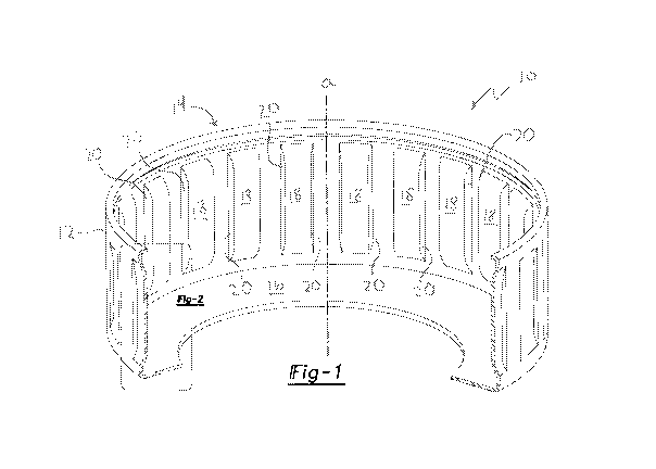
(54) English Title: LANCE-AND-FORM SPLINES WITH FORMED HOUSING LIP SNAP RING RETENTION
(54) French Title: CANNELURES DE PERFORATION ET FORMATION PRESENTANT UNE RETENTION A CLIP CIRCULAIRE A LEVRE DE LOGEMENT FORME
Status: Deemed Abandoned and Beyond the Period of Reinstatement - Pending Response to Notice of Disregarded Communication
Bibliographic Data
(51) International Patent Classification (IPC):
  • F16D 13/68 (2006.01)
  • F16D 13/38 (2006.01)
(72) Inventors :
  • SZUBA, JOSEPH (United States of America)
(73) Owners :
  • VALUE EXTRACTION LLC
  • SZUBA CONSULTING, INC.
(71) Applicants :
  • VALUE EXTRACTION LLC (United States of America)
  • SZUBA CONSULTING, INC. (United States of America)
(74) Agent: GOWLING WLG (CANADA) LLP
(74) Associate agent:
(45) Issued:
(86) PCT Filing Date: 2012-08-13
(87) Open to Public Inspection: 2013-02-21
Examination requested: 2015-08-25
Availability of licence: N/A
Dedicated to the Public: N/A
(25) Language of filing: English

Patent Cooperation Treaty (PCT): Yes
(86) PCT Filing Number: PCT/US2012/050584
(87) International Publication Number: US2012050584
(85) National Entry: 2014-02-10

(30) Application Priority Data:
Application No. Country/Territory Date
13/572,003 (United States of America) 2012-08-10
61/522,797 (United States of America) 2011-08-12

Abstracts

English Abstract

A housing for use with a clutch assembly includes an annular wall disposed around an axis and extending between an open end of the housing and a floor of the housing with the floor extending toward the axis. A plurality of splines are spaced around the annular wall and extends between the open end and the floor. The splines define a work surface for engaging teeth of a clutch plate with the work surface being fractured from the annular wall providing a substantially normal relationship to the annular wall.


French Abstract

La présente invention concerne un logement devant être utilisé avec un ensemble embrayage, qui comprend une paroi annulaire disposée autour d'un axe et s'étendant entre une extrémité ouverte du logement et un fond du logement, le fond s'étendant vers l'axe. Plusieurs cannelures sont espacées sur la paroi annulaire et s'étendent entre l'extrémité ouverte et le fond. Les cannelures définissent une surface de travail pour des dents de mise en prise d'un plateau d'embrayage, la surface de travail étant séparée de la paroi annulaire ce qui forme une relation sensiblement normale avec la paroi annulaire.

Claims

Note: Claims are shown in the official language in which they were submitted.

CLAIMS
What is claimed is:
1. A housing for use with a clutch assembly, comprising:
an annular wall disposed around an axis and extending between an open end
of said housing and a floor of said housing with said floor extending toward
said axis;
a plurality of splines spaced around said annular wall and extending between
said open end and said floor, said splines defining a work surface for
engaging teeth
of a clutch plate with said work surface being fractured from said annular
wall thereby
providing a substantially normal relationship to said annular wall.
2. The housing set forth in claim 1, wherein said annular wall is disposed
on a clutch hub.
3. The housing set forth in claim 1, wherein said annular wall defines a
base surface and each of said splines define a distal surface being spaced
from said
base surface and a proximal surface being proximate to said base surface.
4. The housing set forth in claim 3, wherein said proximal surface is
disposed above said base surface of said annular wall providing a space
between said
proximal surface and said base surface.
5. The housing set forth in claim 3, wherein said proximal surface is
disposed below said base surface of said annular wall.
6. The housing set forth in claim 1, wherein each of said plurality of
splines is spaced from said open end of said housing.
7. The housing set forth in claim 1, wherein said floor of said housing
defines an annular opening.
8. The housing set forth in claim 1, wherein said floor extends to a shaft
disposed at said axis defined by said annular wall.
6

9. The housing set forth in claim 1, wherein said work surfaces of
adjacent said splines are substantially parallel.
10. The housing set forth in claim 1, wherein each of said plurality of
splines include opposing work surfaces being oriented in a substantially
parallel
relationship.
11. The housing set forth in claim 1, wherein plurality of splines extends
toward said axis defined by said annular wall.
7

Description

Note: Descriptions are shown in the official language in which they were submitted.


CA 02844753 2014-02-10
WO 2013/025609 PCT/US2012/050584
LANCE-AND-FORM SPLINES WITH FORMED HOUSING LIP SNAP RING
RETENTION
PRIOR APPLICATIONS
[0001] This Application
claims priority to United States Provisional
Patent Application 61/522,797, filed on August 12, 2011.
FIELD OF THE INVENTION
[0002] The present
invention relates generally towards an improved
clutch hub and clutch housing. More specifically, the present invention
relates to an
improved spline configuration for a clutch hub and clutch housing.
BACKGROUND OF THE INVENTION
[0003] Clutch assemblies
are known to be integral parts of vehicle
transmissions. Clutch housings and hubs define an annular wall circumscribing
a
housing axis. The annular wall defines a plurality of splines that extend from
an open
end to a floor of the housing, and are generally parallel to the axis. The
splines
engage clutch plates in a known manner to shift transmission gears in response
to an
accelerating or decelerating vehicle.
[0004] Presently, splines
are formed in the annular wall of the
housings by a series of die presses or in a progressive die. These dies are
known to be
exceedingly expensive, requiring a press having a high tonnage and associated
transfer system for moving the pre-form to the sequentially arranged dies.
[0005] Additionally, soft
or low strength sheet metal is required to
allow the dies to form each of the splines. Still further, because the splines
are formed
in a die press, die relief is required of each spline to facilitate separating
two halves of
the die after formation. This requires each spline to have a trapezoidal
configuration,
where a work surface is substantially angled to the annular wall providing die
relief.
1

CA 02844753 2014-02-10
WO 2013/025609
PCT/US2012/050584
Due to the trapezoidal shape required of each spline for proper formation, a
limited
number of splines can be formed in the annular wall, reducing surface area of
contact
between the splines and the clutch plate.
[0006 1
Therefore, it would be desirable to provide a new form of
spline to resolve the problems associated with the prior art spline
configuration clutch
housings and hubs.
SUMMARY
[0007] A
housing for use with a clutch assembly includes an annular
wall disposed around an axis and extending between an open end of the housing
and
the floor of the housing. The floor of the housing extends toward the axis. A
plurality of splines are spaced around the annular wall and extend between the
open
end and the floor. The splines define a work surface for engaging teeth of a
clutch
plate with the work surface being fractured from the annular wall, providing a
substantially normal relationship to the annular wall.
[0008]
Fracturing the work surface from the annular wall, also known
as lance and form, solves the mechanical deficiencies associated with the
prior art
clutch housings and hubs. For example, forming a spline through a lance and
form
process eliminates a substantial number of work stations required of a
progressive die
system. This significantly reduces the cost associated with forming the
splines in the
annular wall. Furthermore, the fracturing process used to form a work surface
significantly reduces the width of each spline because die relief is not
required.
Therefore, an increase in the number of splines formed in the annual wall is
now
possible, which increases the surface area of contact between the splines and
the
clutch plates.
2

CA 02844753 2014-02-10
WO 2013/025609 PCT/US2012/050584
BRIEF DESCRIPTION OF THE DRAWINGS
[0009] Other advantages of
the present invention will be readily
appreciated as the same becomes better understood by reference to the
following
detailed description when considered in connection with the accompanying
drawings
wherein:
[0010] Figure 1 shows a
partial perspective view of the clutch housing
of the present application;
[0011] Figure 2 shows a
fragmented side view of the clutch housing
showing the inventive spline of the present application;
[0012] Figure 3 shows a
sectional view through line 3-3 of Figure 2;
and
[0013] Figure 4 shows a
sectional view of an alternative embodiment
of the inventive splines of the present Application.
DETAILED DESCRIPTION
[0014] Referring to Figure
1, a clutch housing of the present invention
is generally shown at 10. The housing 10 includes an annular wall 12 disposed
around an axis a. The wall 12 extends between an open end 14 and a floor 16 of
the
housing 10. The floor 16 extends toward the axis a.
[0015] A plurality of
splines 18 are spaced around the annular wall 12
and extend between the open end 14 and the floor 16 of the housing 10. Each of
the
splines 18 define a work surface 20 for engaging the teeth of a clutch plate
(not
shown). The work surface 20 is fractured from the annular wall 12 providing a
substantially normal relationship of the work surface 20 with the annular wall
12.
[0016] The fracturing of
the work surface 20 from the annular wall 12
is contemplated to be performed by lancing and forming the splines 18 from the
3

CA 02844753 2014-02-10
WO 2013/025609 PCT/US2012/050584
annular wall 12. Although the figures represent the splines 18 protruding from
the
annular wall inwardly toward the axis a, it should be understood by those of
skill in
the art that the splines 18 may also project radially outwardly of the annular
wall 12
away from the axis a. It is further contemplated by the inventor that the
steel used to
form the housing is a high carbon steel ASTM 1030 to 1035 standard. This is
contemplated to be cooperable to harden clutch plates also formed of ASTM 1030
steel.
[0017] Because the work
surfaces 20 of each of the plurality of splines
18 is substantially normal to the annular wall 12, adjacent work surfaces 20
of
adjacent splines 18 are substantially parallel. Figure
1B shows an alternate
embodiment of the present invention at 22 where like numerals represent like
parts to
the first embodiment. In the alternative embodiment, the housing 24 takes the
form of
a clutch hub having a central shaft 24 aligning with the axis a of the
original
embodiment.
[0018] Figure 2 shows an
oil slot 26 defined between the splines 18
and the annular wall 12. The configuration of the oil slots 26 will be
explained
further herein below.
[0019] The housing 10
defines a retainer 28 formed at the open end 14
of the annular wall 12. The retainer 28 is configured to retain a snap ring
(not shown)
in a groove 30. Therefore, it is represented that the plurality of splines 18
are spaced
from the open end of the annular wall 12.
[0020] Referring now to
Figure 3, a sectional view of the annular wall
12 taken through line 3-3 of Figure 2 is shown. The annular wall 12 defines a
base
surface 32. The spline 18 define a distal surface 34 that is spaced from the
base
surface 32, and also define a proximal surface 36 that is proximate to the
base surface
4

CA 02844753 2014-02-10
WO 2013/025609 PCT/US2012/050584
32 of the annular wall 12. In this embodiment, the proximal surface 36 is
spaced from
the base surface 32 of the annular wall 12, providing the oil slot 26 also
represented in
Figure 2. Figure 4 shows an alternate embodiment where the proximal surface 36
is
located below the base surface 32 of the annular wall 12. Therefore, the oil
slots are
closed by virtue of the overlap between the splines 18 and the annular wall
12.
[0021] While the invention
has been described with reference to an
exemplary embodiment, it will be understood by those skilled in the art that
various
changes may be made and equivalents may be substituted for elements thereof
without departing from the scope of the invention. In addition, many
modifications
may be made to adapt a particular situation while material to the teachings of
the
invention without departing from the essential scope thereof. Therefore, it is
intended
that the invention not be limited to the particular embodiment disclosed as
the best
mode contemplated for carrying out this invention but that the invention will
include
all embodiments falling within the scope of the appended claims.

Representative Drawing
A single figure which represents the drawing illustrating the invention.
Administrative Status

2024-08-01:As part of the Next Generation Patents (NGP) transition, the Canadian Patents Database (CPD) now contains a more detailed Event History, which replicates the Event Log of our new back-office solution.

Please note that "Inactive:" events refers to events no longer in use in our new back-office solution.

For a clearer understanding of the status of the application/patent presented on this page, the site Disclaimer , as well as the definitions for Patent , Event History , Maintenance Fee  and Payment History  should be consulted.

Event History

Description Date
Time Limit for Reversal Expired 2017-08-15
Application Not Reinstated by Deadline 2017-08-15
Deemed Abandoned - Failure to Respond to Maintenance Fee Notice 2016-08-15
Letter Sent 2015-09-01
Request for Examination Received 2015-08-25
Request for Examination Requirements Determined Compliant 2015-08-25
All Requirements for Examination Determined Compliant 2015-08-25
Inactive: First IPC assigned 2014-04-04
Inactive: IPC assigned 2014-04-04
Inactive: IPC removed 2014-04-04
Inactive: Cover page published 2014-03-24
Inactive: Notice - National entry - No RFE 2014-03-14
Inactive: Applicant deleted 2014-03-14
Inactive: IPC assigned 2014-03-14
Inactive: First IPC assigned 2014-03-14
Application Received - PCT 2014-03-14
National Entry Requirements Determined Compliant 2014-02-10
Application Published (Open to Public Inspection) 2013-02-21

Abandonment History

Abandonment Date Reason Reinstatement Date
2016-08-15

Maintenance Fee

The last payment was received on 2015-07-29

Note : If the full payment has not been received on or before the date indicated, a further fee may be required which may be one of the following

  • the reinstatement fee;
  • the late payment fee; or
  • additional fee to reverse deemed expiry.

Patent fees are adjusted on the 1st of January every year. The amounts above are the current amounts if received by December 31 of the current year.
Please refer to the CIPO Patent Fees web page to see all current fee amounts.

Fee History

Fee Type Anniversary Year Due Date Paid Date
Basic national fee - standard 2014-02-10
MF (application, 2nd anniv.) - standard 02 2014-08-13 2014-07-21
MF (application, 3rd anniv.) - standard 03 2015-08-13 2015-07-29
Request for examination - standard 2015-08-25
Owners on Record

Note: Records showing the ownership history in alphabetical order.

Current Owners on Record
VALUE EXTRACTION LLC
SZUBA CONSULTING, INC.
Past Owners on Record
JOSEPH SZUBA
Past Owners that do not appear in the "Owners on Record" listing will appear in other documentation within the application.
Documents

To view selected files, please enter reCAPTCHA code :


To view images, click a link in the Document Description column. To download the documents, select one or more checkboxes in the first column and then click the "Download Selected in PDF format (Zip Archive)" or the "Download Selected as Single PDF" button.

List of published and non-published patent-specific documents on the CPD .

If you have any difficulty accessing content, you can call the Client Service Centre at 1-866-997-1936 or send them an e-mail at CIPO Client Service Centre.


Document
Description 
Date
(yyyy-mm-dd) 
Number of pages   Size of Image (KB) 
Description 2014-02-09 5 176
Representative drawing 2014-02-09 1 38
Drawings 2014-02-09 2 139
Claims 2014-02-09 2 46
Abstract 2014-02-09 1 73
Notice of National Entry 2014-03-13 1 194
Reminder of maintenance fee due 2014-04-14 1 111
Acknowledgement of Request for Examination 2015-08-31 1 176
Courtesy - Abandonment Letter (Maintenance Fee) 2016-09-25 1 172
PCT 2014-02-09 6 268
Request for examination 2015-08-24 2 50