Note: Descriptions are shown in the official language in which they were submitted.
CA 02845083 2014-03-03
CHARGING ASSEMBLIES FOR MAINTAINING STERILITY OF
SURGICAL INSTRUMENT BATTERIES DURING CHARGING
BACKGROUND
Technical Field
100011 The present disclosure relates to battery charging and, more
particularly,
to charging assemblies for maintaining sterility of surgical instrument
batteries during
charging of such batteries.
Background of Related Art
100021 Battery-powered surgical instruments are advantageous in that they
obviate the need for cables coupling the device to an electrical outlet or
external power
source. A typical rechargeable battery pack for a battery-powered surgical
instrument
includes a housing containing one or more battery cells coupled to one another
via a
powering circuit through which the battery pack is able to provide electrical
power to the
surgical instrument and receive electrical power from a charger.
100031 Maintaining sterility in a surgical environment reduces the
likelihood of
infection and helps prevent the spread of disease. In order to maintain a
sterile surgical
environment, surgical instrumentation is sterilized and maintained in sterile
condition
prior to entering the sterile surgical environment. Reusable surgical
instruments, or
reusable components of surgical instruments, are thus required to be
sterilized, e.g., via
autoclaving or using a Sterrad system, after each use and/or prior to re-
entering the
sterile surgical environment. Rechargeable battery packs additionally require
charging
after each use or several uses.
1
CA 02845083 2014-03-03
SUMMARY
[0001] As used herein, the term "distal" refers to the portion that is
being
described which is further from a user, while the term "proximal" refers to
the portion
that is being described which is closer to a user. Further, to the extent
consistent, any
of the aspects described herein may be used in conjunction with any or all of
the other
aspects described herein.
[0004] In accordance with aspects of the present disclosure, a charging
assembly
is provided. The charging assembly includes a container and an external
charging
portion. The container includes a base defining an interior volume and a
cover. The
cover is releasably engagable with the base for enclosing the interior volume.
The
container is configured to maintain the interior volume in a sterile
condition. At least one
electrical contact is disposed within the interior volume of the base. The
external
charging portion is operably couplable to the container for charging a battery
assembly
positioned within the interior volume of the base via the at least one
electrical contact.
[0005] In aspects, the container includes at least one charging bay
disposed
within the interior volume. The at least one charging bay is configured to
receive a
battery assembly.
[0006] In aspects, the base of the container is configured for wireless
power
transmission with the external charging portion. More specifically, the base
of the
container may include a support member incorporating an inductive coil and the
external charging portion may include an inductive charging mat. The support
member
and charging mat are configured for wireless power transmission therebetween.
2
CA 02845083 2014-03-03
100071 In aspects, the container includes an exterior receptacle for
coupling the
container to the external charging portion. More specifically, the charging
assembly
may further include a connector cable configured to couple between the
exterior
receptacle of the container and the external charging portion for transmitting
power
therebetween.
100081 In aspects, the container is formed from a sterilizable material.
In
particular, the container may be configured for hydrogen peroxide
sterilization.
100091 A system provided in accordance with the present disclosure
includes a
surgical instrument, a battery assembly, and a charging assembly. The battery
assembly is releasably engagable with the surgical instrument for powering the
surgical
instrument. The battery assembly is sterilizable. The charging assembly
includes a
container having a base configured to receive the battery assembly and a cover
releasably engagable with the base for enclosing the battery assembly within
the
container. The container is configured to maintain the battery assembly in a
sterile
condition. The charging assembly further includes an external charging
portion. The
external charging portion is operably couplable to the container for charging
the battery
assembly.
100101 In aspects, the battery assembly includes at least one electrical
contact
through which the battery assembly is charged and discharged.
100111 In aspects, the container further includes at least one electrical
contact
configured to couple to the at least one electrical contact of the battery
assembly for
charging the battery assembly.
3
CA 02845083 2014-03-03
[0012] In aspects, the container includes a charging bay configured to
receive the
battery assembly.
[0013] In aspects, the base of the container is configured for wireless
power
transmission with the external charging portion. Alternatively, the container
may include
an exterior receptacle for coupling the container to the external charging
portion.
[0014] In aspects, the container and battery assembly are sterilizable
with the
battery assembly disposed within the container. In particular, the container
and battery
assembly may be sterilizable via hydrogen peroxide sterilization.
[0015] A method provided in accordance with aspects of the present
disclosure
includes performing at least one surgical task with a battery-powered surgical
device,
disengaging a battery assembly from the battery-powered surgical device,
sterilizing the
battery assembly, sterilizing a container, enclosing the battery assembly
within the
container, electrically coupling an external charging portion to the container
for charging
the battery assembly, and returning the sterile battery assembly to a sterile
environment.
[0016] In aspects, the step of enclosing the battery assembly within the
container
is performed before sterilizing the battery assembly and sterilizing the
container such
that the battery assembly and container are sterilized with the battery
assembly
enclosed within the container.
[0017] In aspects, the step of coupling the external charging portion to
the
container for charging the battery assembly includes approximating wireless
power
transmission components of the external charging portion and container
relative to one
another.
4
CA 02845083 2014-03-03
[0018] In aspects, the step of coupling the external charging portion to
the
container for charging the battery assembly includes coupling a connector
cable
between the container and the external charging portion.
BRIEF DESCRIPTION OF THE DRAWINGS
[0019] Various aspects of the present disclosure are described hereinbelow
with
reference to the drawings, wherein:
[0020] FIG. 1 is a side, perspective view of a portable, battery-powered
surgical
instrument configured for use in accordance with the present disclosure;
100211 FIG. 2 is a side, perspective view of another portable, battery-
powered
surgical instrument configured for use in accordance with the present
disclosure;
[0022] FIG. 3 is a side, perspective view of a battery assembly provided
in
accordance with the present disclosure and configured for use with either or
both of the
instruments of FIGS. 1 and 2;
100231 FIG. 4 is an exploded, perspective view of the battery assembly of
FIG. 3;
[0024] FIG. 5A is an exploded, perspective view of a sterilization and
charging
container provided in accordance with the present disclosure;
[0025] FIG. 5B is an exploded, perspective view of the sterilization and
charging
container of FIG. 5A including the battery assembly of FIG. 3 disposed
therein;
[0026] FIG. 6A is a perspective view of the sterilization and charging
container of
FIG. 5A shown in conjunction with associated external charging components
provided in
accordance with the present disclosure;
[0027] FIG. 6B is a perspective view of another sterilization and charging
container provided in accordance with the present disclosure and shown in
conjunction
CA 02845083 2014-03-03
with associated external charging components provided in accordance with the
present
disclosure;
100281 Fig. 7A is a perspective view of a sterile wrap housing a charging
device
provided in accordance with the present disclosure; and
[0029] FIG. 7B is a side view of the sterile wrap and charging device
shown in
FIG. 7A.
DETAILED DESCRIPTION
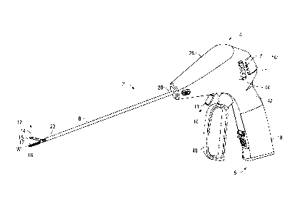
100301 Referring now to FIGS. 1 and 2, FIG. 1 depicts a portable, battery-
powered electrosurgical instrument 2 and FIG. 2 depicts a portable, battery-
powered
ultrasonic surgical instrument 102. For the purposes herein, either an
electrosurgical
instrument, e.g., instrument 2, an ultrasonic instrument, e.g., instrument
102, or any
other suitable battery-powered device, e.g., a surgical instrument, handheld
tool,
electronic device, or the like, may be utilized in accordance with the present
disclosure.
Obviously, different considerations apply to each particular type of device;
however, the
features and aspects of the present disclosure are equally applicable and
remain
generally consistent with respect to any suitable battery-powered device. For
the
purposes herein, electrosurgical instrument 2 and ultrasonic instrument 102
are
generally described.
100311 With reference to FIG. 1, electrosurgical instrument 2, shown as an
electrosurgical forceps, generally includes a housing 4, a battery assembly
18, an
electrosurgical generator 28, a handle assembly 6, a rotating assembly 7, a
shaft 8, a
trigger assembly 10, a drive assembly (not shown), and an end effector
assembly 12.
End effector assembly 12 operatively connects to handle assembly 6 via the
drive
6
CA 02845083 2014-03-03
assembly (not shown) for imparting movement of one or both of jaw members 14,
16 of
end effector assembly 12 between a spaced-apart position and an approximated
position for grasping tissue therebetween.
[0032] Continuing with reference to FIG. 1, shaft 8 is coupled to housing
4 at
proximal end 20 thereof and extends distally from housing 4 to define a
longitudinal axis
"A-k" End effector assembly 12, including jaw members 14 and 16, is disposed
at a
distal end 22 of shaft 8. End effector assembly 12 is shown configured as a
unilateral
assembly wherein jaw member 16 is fixed relative to shaft 8 and jaw member 14
is
pivotable relative to jaw member 16 and shaft 8 between the spaced-apart and
approximated positions. However, this configuration may be reversed, e.g.,
wherein jaw
member 14 is fixed relative to shaft 8 and jaw member 16 is pivotable relative
to jaw
member 14 and shaft 8. Alternatively, end effector assembly 12 may be
configured as a
bilateral assembly, e.g., wherein both jaw members 14, 16 are pivotable
relative to one
another and shaft 8 between the spaced-apart and approximated positions.
100331 Electrosurgical instrument 2 may be configured as a bipolar
instrument.
That is, each of the jaw members 14, 16 may include a respective seal plate
15, 17 that
is configured to function as an active (or activatable) and/or return
electrode. Each seal
plate 15, 17 is electrically coupled to generator 28 via one or more
electrical leads (not
shown) that extend from generator 28, through shaft 8, and eventually coupling
to one
or both of seal plates 15, 17 for conducting energy through tissue grasped
therebetween. However, forceps 2 may alternatively be configured as a
monopolar
instrument.
7
CA 02845083 2014-03-03
[00341
Handle assembly 6 includes a moveable handle 40 that is movable
relative to fixed handle portion 42 for moving jaw members 14, 16 of end
effector
assembly 12 between the spaced-apart and approximated positions. Rotating
assembly 7 is rotatable in either direction about longitudinal axis "A-A" to
rotate shaft 8
and, thus, end effector assembly 12 about longitudinal axis "A-A." Trigger
assembly 10
is in operable communication with a knife assembly (not shown) including a
knife blade
(not shown) that is selectively translatable between jaw members 14, 16 to cut
tissue
grasped therebetween, e.g., upon actuation of trigger 11 of trigger assembly
10.
[00351
With continued reference to FIG. 1, housing 4 is configured to releasably
engage electrosurgical generator 28 and battery assembly 18. Generator 28 is
releasably engagable with body portion 44 of housing 4, while battery assembly
18 is
releasably engagable with fixed handle portion 42 of housing 4. More
specifically,
battery assembly 18 is configured to engage fixed handle portion 42 of housing
4 such
that battery assembly 18 functions as the stationary handle of housing 4 to
facilitate
grasping of the forceps 2. Generator 28 releasably engages body portion 44 of
housing
4 and may be selectively removable from body portion 44 either in connection
with the
removal of battery assembly 18 or independently.
[0036]
When forceps 2 is assembled, generator 28 is disposed in operable
communication with battery assembly 18 to provide electrosurgical energy to
end
effector 12 for electrosurgically treating tissue, e.g., to seal tissue,
although forceps 2
may alternatively be configured to deliver any other suitable form of energy
to tissue,
e.g., thermal energy, microwave energy, light energy, etc.
With respect to
electrosurgical tissue treatment, generator 28 may include suitable
electronics that
8
CA 02845083 2014-03-03
convert the electrical energy from battery assembly 18 into an RF energy
waveform to
energize one or both of jaw members 14, 16. That is, generator 28 may be
configured
to transmit RF energy to seal plate 15 of jaw member 14 and/or seal plate 17
of jaw
member 16 to conduct energy therebetween for treating tissue. Activation
switch 1
disposed on housing 4 is activatable for selectively enabling generator 28 to
generate
and subsequently transmit RF energy to seal plate 15 and/or seal plate 17 of
jaw
members 14, 16, respectively, for treating tissue grasped therebetween.
100371 Referring now to FIG. 2, ultrasonic instrument 102 includes
components
similar to that of forceps 2 shown in Fig. 1, namely, a housing 104, a battery
assembly
118, a generator 128, a handle assembly 106, a shaft 108, and an end effector
assembly 112. Accordingly, only the difference between ultrasonic instrument
102 and
forceps 2 (FIG. 1) will be described in detail below.
[0038] Housing 104 is configured to releasably engage ultrasonic generator
128
and battery assembly 118. Shaft 108 extends distally from housing 104 to
define
longitudinal axis "B-B" and includes end effector assembly 112 disposed at
distal end
122 thereof. One or both of jaw members 114 and 116 of end effector assembly
112
are movable relative to one another, e.g., upon actuation of moveable handle
124,
between an open position and a clamping position for grasping tissue
therebetween.
Further, one of the jaw members, e.g., jaw member 116, serves as an active or
oscillating ultrasonic blade that is selectively activatable to ultrasonically
treat tissue
grasped between jaw members 114, 116.
[0039] Generator 128 includes a transducer (not shown) configured to
convert
electrical energy provided by battery assembly 118 into mechanical energy that
9
CA 02845083 2014-03-03
produces motion at the end of a waveguide, e.g., at blade 116. More
specifically, the
electronics (not explicitly shown) of the generator 128 convert the electrical
energy
provided by battery assembly 118 into a high voltage AC waveform that drives
the
transducer (not shown). When the transducer (not shown) and the waveguide are
driven at their resonant frequency, mechanical, e.g., ultrasonic, motion is
produced at
the active jaw member 116 for treating tissue grasped between jaw members 114,
116.
Further, an activation button 110 disposed on housing 104 is selectively
activatable to
operate instrument 102 in two modes of operation: a low-power mode of
operation and
a high-power mode of operation.
[0040] With reference to FIGS. 3-4, battery assembly 118 generally
includes an
outer housing 130, a battery pack 140, battery circuitry 159, and a contact
cap 180.
Battery assembly 18 of electrosurgical instrument 2 (FIG. 1) may be configured
similarly
to battery pack 118 and, thus, will not be described herein for purposes of
brevity.
[0041] Outer housing 130 of battery assembly 118 is formed from first and
second housing parts 132, 134 that cooperate to house battery pack 140 and
battery
circuitry 159. Housing parts 132, 134 define cut-outs 133, 135, respectively,
that
cooperate to form a window configured to retain contact cap 180. Contact cap
180 is
electrically coupled to battery circuitry 159, which, in turn, is electrically
coupled to
battery pack 140. Contact cap 180 includes a plurality of contacts 182
configured to
provide an electrical interface between battery assembly 118, e.g., battery
pack 140 and
battery circuitry 159, and both the battery-powered device, e.g.,
electrosurgical
instrument 2 (FIG. 1) or ultrasonic instrument 102 (Fig. 2), and battery
charging device,
e.g., charging assembly 200 (FIG. 6A), charging assembly 300 (FIG. 66), or
charging
CA 02845083 2014-03-03
assembly 400 (FIGS. 7A-7B), for transmitting power and/or control signals
therebetween. Battery pack 140 includes a plurality of battery cell assemblies
142a,
142b, 142c, 142d, e.g., four (4) battery cell assemblies 142a-142d, although
greater or
fewer battery cell assemblies 142a-142d are also contemplated.
[0042] Turning now to FIGS. 5A-7B, with respect to the sterilization of
battery
assemblies, it has been found that the risk of thermal runaway and/or other
damage to
the battery assembly is increased in instances where the state of charge of
the battery
assembly approaches 100%, e.g., when the battery is fully or near-fully
charged. Thus,
after use, it is desirable to sterilize the battery assembly prior to charging
the battery
assembly, rather than the other way around. However, sterilizing the battery
assembly
prior to charging the battery assembly requires that the battery assembly be
maintained
in sterile condition during the charging process. Accordingly, the present
disclosure
provides various embodiments of charging assemblies 200, 300, 400 (FIGS. 5A-
6A, 6B,
and 7A-7B, respectively) configured for charging battery assembly 118 (FIGS. 3-
4), or
any other suitable rechargeable battery assembly, while maintaining battery
assembly
118 (FIGS. 3-4) in a sterile condition and/or allowing for sterilization of
battery assembly
118 (FIGS. 3-4). Each of charging assemblies 200, 300, 400 (FIGS. 5A-6A, 6B,
and
7A-7B, respectively) will be described in greater detail, in turn, below.
[0043] Referring to FIGS. 5A-6A, charging assembly 200 is shown generally
including a sterilization and charging container 210 (FIGS. 5A-5B) and an
external
charging portion 240 (FIG. 6A). Sterilization and charging container 210
generally
includes a base 212 and a cover 222 that cooperate to fully enclose and retain
battery
assembly 118 therein. Container 210 is formed from a sterilizable material,
e.g.,
11
CA 02845083 2014-03-03
thermoplastics such as polycarbonate and low-density polyethylene (LDPE),
and/or is
wrapped in a sterilizable wrapping, e.g., synthetic wrappings such as Tyvek .
[00441
With reference to FIGS. 5A-5B in particular, base 212 of container 210
defines a generally rectangular configuration, although other configurations
are
contemplated. Base 212 includes a planar support member 213, a pair of opposed
long
walls 215 and a pair of opposed short walls 216. Long and short walls 215,
216,
respectively, are disposed about the outer periphery of planar support member
213 so
as to define an interior volume within base 212. Planar support member 213
defines an
interior surface 214a, and an exterior surface 214b and incorporates inductive
charging
components, e.g., an inductive coil, for inductively charging battery assembly
118 upon
abutment of exterior surface 214b of planar support member 213 and charging
surface
244 of external charging portion 240 (FIG. 6A), as will be described in
greater detail
below. The inductive charging components may include any suitable components
and/or features known in the art. As an alternative to inductive charging,
planar support
member 213 may include any other suitable wireless charging components know in
the
art.
[00451 A
charging bay 217 is disposed on interior surface 214a of planar support
member 213 and is configured to at least partially receive battery assembly
118.
Charging bay 217, or a portion thereof, may be shaped complementary to battery
assembly 118 to retain battery assembly 118 in position within base 212 during
transport of container 210. A
plurality of contacts 218 electrically coupled to the
inductive components of planar support member 213 and configured to
electrically mate
with two or more of contacts 182 (FIGS. 3-4) of battery assembly 118 are
disposed
12
CA 02845083 2014-03-03
within charging bay 217 such that, upon seating of battery assembly 118 within
charging
bay 217, contacts 182 (FIGS. 3-4) and contacts 218 electrically mate with one
another.
It is also envisioned that base 212 of container 210 include a plurality of
charging bays
217 for retaining a plurality of battery assemblies 118 therein.
100461 Short walls 216 of base 212 each include one or more engagement
features, e.g., protrusions 219a, respectively, configured to releasably
engage
corresponding engagement features, e.g., dimples 229 of flanges 228 of cover
222.
Alternatively or additionally, the engagement features may be disposed on long
walls
215. Short walls 216 further define cut-outs 219b configured to facilitate the
grasping of
base 212 during transport and/or to facilitate engaging and removing cover 222
from
base 212.
100471 Continuing with reference to FIGS. 5A-5B, cover 222 of container
210
includes a planar member 224 and an overhang 226 extending about the outer
periphery of planar member 224. Planar member 224 is dimensioned similarly to
planar
support member 213 of base 212 such that, upon positioning of cover 222 about
base
212, overhang 226 is disposed about and positioned in abutting relation with
walls 215,
216 of base 212 to engage cover 222 about base 212. Overhang 226 of cover 212
includes a pair of flanges 228 extending from opposed sides thereof (only one
flange
228 is shown). Flanges 228 are configured to extend along short walls 216 of
base 212
and, as mentioned above, each flange 228 includes a dimple 229 configured to
receive
a respective protrusion 219a of base 212 to releasably engage cover 222 about
bases
212. Flanges 228 are resiliently movable relative to cover 222 to permit a
user to
disengage protrusions 219a from dimples 229 to release cover 222 from base
212.
13
CA 02845083 2014-03-03
Other suitable releasable engagement mechanisms for engaging cover 222 about
base
212 and/or for facilitating the releasable engagement of cover 222 about base
212 are
also contemplated.
100481 Turning now to FIG. 6A, in conjunction with FIGS. 5A-5B, external
charging portion 240 of charging assembly 200 includes a charging mat 242
defining a
charging surface 244. A power cord 246 is coupled to and extends from charging
mat
242. Charging mat 242 incorporates indicative charging components, e.g., an
inductive
coil, or other suitable components for wirelessly providing power to container
210, for
charging battery assembly 118. Power cord 246 includes a receptacle 248 for
coupling
external charging portion 240 to a standard outlet (not shown), although other
configurations are also contemplated. External charging portion 240 need not
be
sterilizable or maintained in sterile condition since, as can be appreciated,
battery
assembly 118 can be maintained within container 210, in sterile condition,
while being
charged by external charging portion 240 via the wireless power transfer
between
charging mat 242 and planar support member 213 of container 210 and,
ultimately, the
electrically coupled contacts 218, 182 of container 210 and battery assembly
118,
respectively.
100491 Turning now to FIG. 6B, another embodiment of a charging assembly
provided in accordance with the present disclosure is shown generally
identified by
reference numeral 300. Charging assembly 300 includes a sterilization and
charging
container 310 that is similar to and may include any of the features of a
sterilization and
charging container 210 of charging assembly 200 (FIG. 5A-6A). Accordingly,
only the
differences between charging assembly 300 and charging assembly 200 (FIGS. 5A-
6A)
14
CA 02845083 2014-03-03
will be described in detail below for purposes of brevity. Charging assembly
300 further
includes an external charging portion 340.
[0050] Container 310 of charging assembly 300 includes a connector cable
330
extending from one of the walls that forms base 312 of container 310. More
specifically,
base 312 of container 310 includes a receptacle 332 disposed on an external
surface
thereof that is configured to engage first end 333 of connector cable 330.
First end 333
of connector cable 330 may be releasably engagable with receptacle 332 or may
be
fixedly engaged thereto. Receptacle 332 is electrically coupled to the
contacts disposed
within the charging bay (not explicitly shown; similar to contacts 218 and
charging bay
217 of container 210 (FIGS. 5A-5B)) of container 310. Further, it is
envisioned that
connector cable 330, similarly as container 310, be sterilizable, at least in
embodiments
where connector cable 330 is fixedly engaged to container 310.
[0051] Connector cable 330 extends to a second end 335 thereof that
includes a
plug 336. Plug 336 is configured to releasably engage a slot 344 defined
within base
member 342 of external charging portion 340 charging assembly 300, although
other
suitable releasable engagement mechanisms are also contemplated. For example,
rather than being fixedly engaged to container, connector cable 330 may be
fixedly
engaged to external charging portion 340. Base member 342 houses suitable
circuitry
for transmitting controlling the power supplied to connector cable 330 and,
ultimately, to
container 310 for charging battery assembly 118 (FIGS. 3-4). Base member 342
further
includes a power cord 346 having a plug 348 at the free end thereof for
coupling
charging portion 340 to a standard outlet (not shown), although other
configurations are
also contemplated. Similarly as described above with respect to external
charging
CA 02845083 2014-03-03
portion 240 (FIG. 6A), external charging portion 340 need not be sterilizable
nor
maintained in sterile condition.
[0052] Referring again to FIGS. 5A-6A, in conjunction with FIGS. 2 and 3,
the use
and operation of charging assembly 200 for charging battery assembly 118 is
described. The use and operation of charging assembly 300 (FIG. 6B) is similar
to that
of charging assembly 200 and, thus, will not be described herein to avoid
unnecessary
repetition.
[0053] Initially, with battery assembly 118 engaged to ultrasonic
instrument 102,
ultrasonic instrument 102 is be used to perform one or more surgical tasks
during a
surgical procedure. At the completion of the surgical procedure, battery
assembly 118
is removed from ultrasonic instrument 102 and is sterilized, e.g., via steam
sterilization
(by placing battery assembly 118 in an autoclave), hydrogen peroxide
sterilization (for
example, using the Sterrad system), or other suitable sterilization
technique. As
mentioned above, sterilizing battery assembly 118 prior to charging reduces
the
likelihood of thermal runaway or other damage to battery assembly 118. If not
already
sterilized, container 210 may also be sterilized separately or with battery
assembly 118
disposed therein. In one particular embodiment, battery assembly 118 is
properly
seated within base 212 of container 210 and cover 222 of container 210 may be
engaged about base 212 to enclose battery assembly 118 within container 210
prior to
sterilization. Thereafter, battery assembly 118 and container 210 may be
sterilized
together as a unit, without requiring removal of battery assembly 118. In some
situations, it may be desirably to clean battery assembly 118, e.g., wipe down
battery
16
CA 02845083 2014-03-03
assembly 118, prior to placing battery assembly 118 within container 210 for
sterilization.
[0054] Once battery assembly 118 is sterilized, battery assembly 118 is
placed in
base 212 of container 210 (if not sterilized within container 210), such that
battery
assembly 118 is properly seated within charging bay 217 with contacts 218 of
container
210 and contacts 182 of battery assembly 118 electrically coupled to one
another.
Thereafter, cover 222 is engaged about base 212 to enclose battery assembly
118
within container 210. The positioning of battery assembly 118 within container
210 and
the engagement of cover 222 of container about base 212 of container 210 is
performed
in a sterile environment so as not to expose battery assembly 118 or the
interior of
container 210 to unsterile conditions. Thereafter, container 210 may be
removed from
the sterile environment without compromising the sterility of battery assembly
118, as
battery assembly 118 is enclosed within container 210.
[0055] With battery assembly 118 enclosed within container 210, container
210
may be placed on charging mat 242 to charge battery assembly 118. As can be
appreciated, the non-sterile external charging portion 240 of charging
assembly 200
allows for the charging of battery assembly 118 without compromising the
sterility of
battery assembly 118. Referring additionally to FIG. 6B, with respect to
charging
assembly 300, cable connector 330 is coupled between base member 342 of
external
charging portion 340 and container 310 to likewise charge battery assembly 118
without
compromising its sterility. Once battery assembly 118 is sufficiently charged,
battery
assembly 118 can be removed from container 210 in a sterile manner and to the
sterile
surgical environment, eventually for engagement with a surgical instrument,
e.g., a new
17
CA 02845083 2014-03-03
or sterilized ultrasonic instrument 102 (FIG. 2), for subsequent use of
battery assembly
118. Although the use of charging assembly 200 is described above in a
particular
order, it is envisioned that the above-described steps of use be performed in
any
suitable order, depending on the circumstances.
100561 Turning now to FIGS. 7A-7B, also provided in accordance with the
present
disclosure is a charging assembly 400 that generally includes a charging base
410 and
a sterile wrap or enclosure 420 sealing the charging base 410 within enclosure
420.
Charging base 410 is shown including a plurality of charging bays 412, each of
which is
configured to receive a battery assembly 118 for charging the battery assembly
118.
Each charging bay 412 further includes a plurality of LED's 414 associated
therewith
and configured to indicate a charging status and/or charging condition of the
battery
assembly 118 being charged therein. A power cord 416 extends from charging
base
410. Power cord 416 includes a plug 418 disposed at the free end thereof for
coupling
charging base 410 to a standard wall outlet (not shown), although other
configurations
are also contemplated. Further, charging base 410 may include any additional
or
alternative features and/or components known in the art to facilitate the
charging of
battery assemblies, e.g., one or more of battery assemblies 118.
100571 Continuing with reference to FIGS. 7A-7B, enclosure 420 surrounds
and
encloses charging base 410. Enclosure 420 serves as a sterile barrier to
maintain
charging base 410 in sterile condition. It is contemplated that charging base
410 be
sterilized, e.g., as a last phase of manufacturing, and placed in enclosure
420 during
manufacture or, alternatively, that a sterile charging base 410 be
positionable within
enclosure 420 by the end-user to maintain its sterility.
18
CA 02845083 2014-03-03
[0058] It is envisioned that enclosure 420 be formed from a
transparent material
to allow visualization of a charging base 410 for monitoring charging of
battery
assemblies 118 or other similarly purposes. As best shown in FIG. 7B,
enclosure 420
includes first and second flaps 422, 424 that overlap one another in a closed
position to
fully enclose charging base 410. Flaps 422, 424 are movable from this closed
position
' to an open, spaced-apart position to permit insertion and/or removal of
battery
assemblies into enclosure 420. Flaps 422, 424 may be retained in the
overlapping,
closed position via friction or any other suitable mechanism, e.g., magnets,
snaps,
tongue and groove engagement, etc.
[0059] With continued reference to FIGS. 7A-7B, enclosure 420 further
includes
an aperture 426 defined therethrough that is configured to receive power cord
416 of
charging base 410. Aperture 426 allows power cord 416 to extend through
enclosure
420 such that charging base 410 may be maintained within enclosure 420 in
sterile
condition while allowing plug 418 of power cord 416 to extend outside the
sterile barrier
for engagement with a wall outlet (not shown) for powering charging base 410.
Aperture 426 may be surrounded by an 0-ring 428 or other suitable sealing
member,
e.g., a sealing gasket, compression ring, etc., for sealing about power cord
416.
100601 In use, rather than charging battery assembly 118 prior to
sterilization
which, as mentioned above, may damage battery assembly 118, battery assembly
118
may be sterilized and then transferred in a sterile manner into enclosure 420
and, more
specifically, into engagement with one of charging bays 412 of charging base
410.
Thus, battery assembly 118 can be charged without compromising the sterility
of battery
assembly 118.
19
CA 02845083 2014-03-03
[0061]
While several embodiments of the disclosure have been shown in the
drawings, it is not intended that the disclosure be limited thereto, as it is
intended that
the disclosure be as broad in scope as the art will allow and that the
specification be
read likewise. Therefore, the above description should not be construed as
limiting, but
merely as exemplifications of particular embodiments. Those skilled in the art
will
envision other modifications within the scope and spirit of the claims
appended hereto.