Note: Descriptions are shown in the official language in which they were submitted.
CA 02845403 2014-02-14
WO 2013/025213 PCT/US2011/048130
DUAL STROKE MECHANICALLY LATCHED MECHANISM
BACKGROUND
[0001] The present disclosure relates generally to the field of latching
mechanisms. More
specifically, the present disclosure relates to the field of solenoid actuated
electromechanical switches.
[0002] In the field of capacitor switches (e.g., vacuum interrupter based
voltage switches)
an operating rod is used to separate electrical contacts and bring the
electrical contacts
together. Conventional switches use magnetic actuators to move the operating
rod to
separate electrical contacts and bring the electrical contacts together.
Magnetic actuators
use rare Earth magnets to hold the operating rod at the end of each stroke,
are costly, and
require sophisticated controls. Other conventional switches use motor operated
spring
loaded mechanisms to move the operating rod to separate electrical contacts
and bring the
electrical contacts together. Motor operated spring loaded mechanisms are
complex, costly,
and have limited speeds. Other switches have used solenoid actuated mechanisms
to move
the operating rod that either require one solenoid for each direction of
travel or require
electronic controls to maintain current at the end of each stroke. These
requirements
increase reliability concerns and cost.
[0003] There is a need for an improved latching mechanism. Thus, there is also
a need for
a switch that includes a lower cost mechanism for moving the operating rod.
Further still,
there is a need for a system for and method of moving an operating rod that
does not require
one solenoid for each direction of travel or require electronic controls to
maintain current at
the end of each stroke. Yet further, there is a need for an actuator that does
not require rare
Earth magnets.
SUMMARY
[0004] One embodiment of the disclosure relates to a switch for an electrical
circuit. The
switch includes a base, a cam rotatably coupled to the base and defining a
first profile and a
second profile, a solenoid comprising alternating first and second cycles, a
liffl( including a
first portion and a second portion, and a member configured to move between an
extended
position and a retracted position and comprising a cam follower configured to
follow the
second profile. The first profile of the cam includes a first position, a
second position, a
-1-
CA 02845403 2014-02-14
WO 2013/025213 PCT/US2011/048130
third position, and a fourth position. The first cycle of the solenoid
includes a first
energized state and a first de-energized state and the second cycle of the
solenoid includes a
second energized state and a second de-energized state. The first portion of
the liffl( couples
to the solenoid, and the second portion of the liffl( movably couples to the
first profile of the
cam. When the solenoid is in the first cycle, the member moves from the
retracted position
to the extended position, and when the solenoid is in the second cycle, the
member moves
from the extend position to the retracted position.
[0005] Another embodiment relates to a switch for an electrical circuit. The
switch
includes a solenoid having alternating energized and de-energized states, a
cam defining a
first profile and a second profile, a link having a first portion and a second
portion, and a
member configured to move between an extended position and a retracted
position and
comprising a cam follower configured to follow the second profile. The first
portion of the
link couples to the solenoid, and the second portion of the link movably
couples to the first
profile. The cam is configured such that alternating energized states of the
solenoid cause
opposite linear motion of the member.
[0006] Another embodiment relates to a latching system. The latching system
includes a
solenoid having a first energized state and a second energized state, a member
configured to
translate between an extended position and a retracted position, and a
mechanical linkage
operatively coupling the solenoid to the member, the mechanical linkage having
a first
orientation and a second orientation. The mechanical linkage is configured
such that when
the solenoid is in the first energized state, the member moves from the
retracted position to
the extended position and the mechanical linkage moves from the first
orientation to the
second orientation. The mechanical linkage is further configured such that
when the
solenoid is in the second energized state, the member moves from the extended
position to
the retracted position and the mechanical linkage moves from the second
orientation to the
first orientation.
[0007] Another embodiment relates to a switch. The switch includes an
operating rod
having a first position and a second position, and a solenoid actuator for
moving the
operating rod from the first position to the second position and from the
second position to
the first position. The solenoid actuator includes only one solenoid for
causing travel in
each direction between the first position and the second position and does not
require
electronic controls to maintain current at the first position and the second
position.
-2-
CA 02845403 2014-02-14
WO 2013/025213 PCT/US2011/048130
BRIEF DESCRIPTION OF THE DRAWINGS
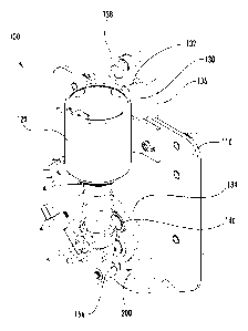
[0008] FIG. 1 is a perspective view of a latching mechanism, shown according
to an
exemplary embodiment.
[0009] FIG. 2 is a front planar view of the latching mechanism of FIG. 1.
[0010] FIG. 3 is a right side planar view of the latching mechanism of FIG. 1.
[0011] FIG. 4 is a rear planar view of the latching mechanism of FIG. 1.
[0012] FIG. 5 is an exploded view of the latching mechanism of FIG. 1.
[0013] FIG. 6 is an enlarged view of a component of the latching mechanism of
FIG. 1,
shown according to an exemplary embodiment.
[0014] FIG. 7 is a front planar view of the latching mechanism of FIG. 1,
shown in an
exemplary second arrangement.
[0015] FIG. 8 is a front planar view of the latching mechanism of FIG. 1,
shown in an
exemplary third arrangement.
[0016] FIG. 9 is a front planar view of the latching mechanism of FIG. 1,
shown in an
exemplary fourth arrangement.
DETAILED DESCRIPTION
[0017] Referring generally to the FIGURES, a latching mechanism and components
thereof are shown according to an exemplary embodiment. The latching mechanism
generally includes a solenoid, an operating rod, and a mechanical linkage
(shown to include
a cam) coupling the solenoid to the operating rod. Actuation of the mechanical
linkage
causes the operating rod to move between a retracted position and an extended
position.
Further, the linkage provides a toggle action. That is, each time the solenoid
is actuated, it
provides the opposite linear motion on the operating rod. Accordingly, a
single-direction
solenoid may be used to provide both push and pull functionality, thereby
reducing cost and
complexity, which, in turn, increases reliability.
[0018] According to an exemplary embodiment, the latching system may be used
as
vacuum interrupter based medium voltage capacitor switch. In such an
embodiment, the
operating rod may be configured to selectively couple at least two electrical
contacts in
response to movement between the refracted position and the extended position.
The
medium voltage switch may be used in utility power distribution environments,
for
-3-
CA 02845403 2014-02-14
WO 2013/025213 PCT/US2011/048130
example, in a pole-mounted or pad-mounted interrupter, operating in circuits
of 15,000
Volts to 35,000 Volts and 200 amps to 400 amps.
[0019] While the exemplary embodiment may be configured as an
electromechanical
switch, it is contemplated that the mechanism disclosed herein may be used in
any
application where push and pull functionality is required, for example, as a
latch or deadbolt
for a door, gate, or safe.
[0020] Before discussing further details of the latching mechanism and/or the
components
thereof, it should be noted that references to "front," "back," "rear,"
"upward,"
"downward," "inner," "outer," "right," and "left" in this description are
merely used to
identify the various elements as they are oriented in the FIGURES. These terms
are not
meant to limit the element which they describe, as the various elements may be
oriented
differently in various applications.
[0021] It should further be noted that for purposes of this disclosure, the
term coupled
means the joining of two members directly or indirectly to one another. Such
joining may
be stationary in nature or moveable in nature and/or such joining may allow
for the flow of
fluids, electricity, electrical signals, or other types of signals or
communication between the
two members. Such joining may be achieved with the two members or the two
members
and any additional intermediate members being integrally formed as a single
unitary body
with one another or with the two members or the two members and any additional
intermediate members being attached to one another. Such joining may be
permanent in
nature or alternatively may be removable or releasable in nature.
[0022] Referring to FIGS. 1-6, a latching mechanism 100 and components thereof
are
shown according to an exemplary embodiment. A base 110 is shown supporting a
solenoid
120, a member (e.g., finger, bar, rod, etc.), shown as an operating rod 130,
and a mechanical
linkage 150. According to the embodiment shown, the base 110 is approximately
6 inches
(15 cm) wide and approximately 8 inches (20 cm) tall. However, the latching
mechanism
100 can easily be scaled up or down in size to suit the desired application.
[0023] The solenoid 120 includes a housing 122 and an armature or plunger 124.
The
plunger 124 extends from the housing 122 to a distal end 126 and defines a
longitudinal axis
L. When the solenoid 120 is energized, the distal end 126 moves towards the
housing 122
along the axis L to an energized position, as shown in FIGS. 7 and 9. When the
solenoid
120 is de-energized, a spring 128 causes the distal end 126 to move away from
the housing
122 and to return to a de-energized position, as shown in FIGS. 1-4 and 8.
According to the
-4-
CA 02845403 2014-02-14
WO 2013/025213 PCT/US2011/048130
embodiment shown, the solenoid 120 couples to base 110 with fasteners 112.
Using
fasteners facilitates replacement of the solenoid 120, which facilitates
repair and enables the
solenoid 120 to be exchanged for a solenoid having different characteristics
(e.g., speed,
strength, etc.). According to alternative embodiments, the solenoid 120 may be
welded,
adhered, or otherwise coupled to the base 110.
[0024] The operating rod 130 may be movably coupled to base 110. The operating
rod
130 translates between a refracted position, as shown in FIGS. 1-4 and 9, and
an extended
position shown in FIGS. 7 and 8. According to the embodiment shown, the
distance
between the extended position and the retracted position is approximately 0.4
inches (1 cm).
The length of the stroke of the operating rod 130 may be modified by changing
the stroke of
the solenoid 120 and/or the configuration of the mechanical linkage 150.
[0025] The operating rod 130 includes a first end 132 and a second end 134.
The
operating rod 130 may also include rearward extending flanges 136, which
provides
strength and may be configured to guide the movement of the operating rod 130
in a
channel 114 defined by the base 110. The first end 132 may include a forwardly
extending
flange 138. According to the embodiment shown, the first end 132 is configured
to
indirectly push together separate electrical contacts via an extension coupled
to the flange
138, but may be configured to directly connect and disconnect the contacts.
The second end
134 includes a cam follower 140.
[0026] The cam follower 140 is shown to be supported by a fastener 142, which
extends
through the operating rod 130 and an arm or blade 144. Referring to FIG. 4,
the blade 144
is rotatably coupled to a rear side of base 110 with a fastener 146. As blade
144 pivots
about fastener 146, fastener 142 sweeps an arc to which the stroke of the
operating rod 130
is substantially tangential. Further, since the stroke of the operating rod
130 is short relative
to the distance from the pivot (e.g., fastener 146) to the arc (e.g., fastener
142), the arc
swept by the blade 144 at the fastener 142 as it rotates about fastener 146 is
approximately
linear. Accordingly, the blade 144 couples the operating rod 130 to the base
110 while
permitting substantially linear motion of the operating rod 130. According to
alternative
embodiments, the cam follower 140 may be the head of the fastener or may be
integrally
formed as part of the operating rod 130.
[0027] A mechanical linkage 150 is shown to include a bar (e.g., finger,
member, linkage,
etc.), shown as a link 160, and a structure (e.g., plate, member, rotor,
etc.), shown as a cam
200. The link 160 includes a first portion 162 and a second portion 164,
located opposite
-5-
CA 02845403 2014-02-14
WO 2013/025213 PCT/US2011/048130
first portion 162. The first portion 162 is rotatably coupled to distal end
126 of plunger 124,
thereby allowing the second portion 162 to depart from the axis L of the
plunger 124 during
the energizing and de-energizing cycles. The second portion 164 includes a cam
driver 166,
which may be coupled to the liffl( 160 or integrally formed as part of the
link 160. Referring
to FIG. 4, the cam driver 166 may be seen through a hole 119 in the base 110
when the
operating rod 130 is in a retracted position and the solenoid 120 is de-
energized. Viewing
cam driver 166 in this position from the rear side of base 110 enables a user
(e.g., a
technician) to confirm that the switch is open (i.e., powered off) before
beginning repairs.
[0028] Referring to FIG. 6, the cam 200 defines a hole or aperture defined by
the cam
200, shown as an opening 202, a first profile (e.g., slot, channel, groove,
etc.), shown as a
driving profile 210, and a second profile (e.g., slot, channel, groove, etc.),
shown as an
operating profile 250. A bearing 152 is located in the opening 202 and
supports the cam
200 while permitting rotation of the cam 200 relative to the base 110. The cam
200 and the
bearing 152 may be coupled to the base 110 by a fastener 154. The driving
profile 210 is
configured to receive the cam driver 166 coupled to the link 160, and the
operating cam
profile 250 is configured to receive the cam follower 140 coupled to the
operating rod 130.
Accordingly, the mechanical linkage 150 operatively couples the solenoid 120
to the
operating rod 130. According to various alternative embodiments, the cam 200
may be
replaced by a multi-bar linkage mechanism.
[0029] The driving profile 210 is shown to have an inner contour 213 and an
outer contour
214 and to comprise a plurality of segments, shown as a first segment 221, a
second
segment 222, a third segment 223, and a fourth segment 224. The first segment
221 extends
at an angle from the second segment 222 to a first end 216. The first segment
221 and the
second segment 222 form an outwardly convex first corner 231 of the inner
contour 213 and
form an inwardly concave first corner 241 of the outer contour 214. The second
segment
222 and the third segment 223 are substantially continuous and follow a
somewhat
circumferential path around opening 202. The fourth segment 224 extends at an
angle from
the third segment 223 to a second end 218. The fourth segment 224 and the
third segment
223 form an outwardly convex second corner 232 of the inner contour 213 and
form an
inwardly concave second corner 242 of the outer contour 214.
[0030] The distance from the first corner 241 to the second corner 242 of the
outer
contour 214 is greater than the distance from the first corner 231 to the
second corner 232 of
inner contour 213. The first corner 231 of the inner contour 213 is closer to
the longitudinal
-6-
CA 02845403 2014-02-14
WO 2013/025213 PCT/US2011/048130
axis L of the plunger 124 than is the first corner 241 of the outer corner
214. Similarly, the
second corner 232 of the inner contour 213 is closer to the longitudinal axis
L of the plunger
124 than is the second corner 242 of the outer corner 214. Accordingly, when
the solenoid
120 is in a de-energized state and the cam driver 166 rests in either the
first corner 241 or
the second corner 242 of the outer contour 214, the cam driver 166 is biased
to enter the
first segment 221 or the fourth segment 224, respectively, when solenoid 120
is energized.
According to alternative embodiments, the driving profile 210 may comprise
other shapes,
e.g., a substantially V-shaped opening having a wide base such the cam driver
166 is biased
to one side or the other of the fork in the V when the solenoid 120 is de-
energized.
[0031] The operating profile 250 is shown to include a first portion, shown as
a retracted
portion 251, and a second portion, shown as a transition portion 252, and a
third portion,
shown as an extend portion 253. The retracted portion 251 includes a radially
outward
turned end which prevents cam 200 from rotating in response to force applied
to operating
rod 130, thereby retaining operating rod 130 in a retracted position. The
transition portion
252 extends between the retracted portion 251 and the extended portion 253 and
is
configured to cause the operating rod 130 to move between a retracted position
and an
extended position in response to rotation of the cam 200 about the bearing
152. The
extended portion 253 is configured to retain the operating rod 130 in an
extended position.
For example, the extended portion 253 includes a constant radius about the
opening 202
which prevents rotation of the cam 200 in response to force applied to the
operating rod 130
and prevents retraction of the operating rod 130 in response to minor rotation
of the cam
200. Accordingly, the operating rod 130 may be mechanically latched at either
the
extended position or the retracted position. The operating profile 250 may
also be
configured to provide torque multiplication. According to the exemplary
embodiment, the
solenoid 120 provides 30 pounds (133 newtons) of force, whereas operating rod
130
provides over 100 pounds (445 newtons) of force to the electrical contacts.
[0032] Referring to FIGS. 3-4, the cam 200 may include a flange 270, which
includes a
radially outward extending portion 272 and a rearward extending portion 274.
The
rearward extending portion 274 extends from a front side or cam side of the
base 110 to a
back side or handle side of the base 110. On the back side of the base 110,
the flange 270 is
coupled to a lever or handle 170 by a spring 172, the handle 170 being
rotatably coupled to
the base 110 by a fastener 174. As the cam 200 rotates between a first or
retracted
orientation (shown in FIGS. 2 and 9) and a second or extended orientation
(shown in FIGS.
-7-
CA 02845403 2014-02-14
WO 2013/025213 PCT/US2011/048130
7-8), the rearward extending portion 274 of the flange 270 concentrically
follows a curved
edge 118 of base 110. In turn, the handle 170 rotates between a first or
retracted position
and a second or extended position as it is pulled by the spring 172. The
handle 170 may be
used for manual override of the cam 200. That is, the cam 200 will rotate
between the
extended and retracted orientations in response to movements of the handle 170
between the
extended and retracted positions, respectively. According to alternative
embodiments, the
handle 170 may be located forward of the base 110, or the flange 270 may be
configured to
be a handle, e.g., extend outward so as to provide a gripping surface for a
user.
[0033] The lever mechanism of handle 170 may further be configured to retain
the cam
200 in extended or retracted orientations. The flange 270 sweeps a
substantially circular arc
around the curved edge 118 as the cam 200 rotates, the curved edge 118 of base
110
following an arc of substantially constant radius around the fastener 154. As
shown, the
axis of rotation of the handle 170 (e.g., the fastener 174) is diametrically
opposite the axis of
rotation of the cam 200 (e.g., the fastener 154) from the midpoint of the arc
of the curved
edge 118. Accordingly, the distance from the handle 170 to the rearward
extending portion
of the flange 270 is greater when the cam 200 is between the extended and
retracted
orientations than when the cam 200 is in one of the extended orientation and
retracted
orientation. As such, when the cam 200 rotates from the retracted orientation
to the
extended orientation, the spring 172 stretches, and the tensile forces in the
spring increase,
until the apex of the curved path of the flange 270 is reached. As the cam 200
continues to
rotate passed the apex of the curve, the spring 172 decreases in length until
the extended
orientation is reached. Rotating the cam 200 back to the retracted orientation
would require
again stretching the spring 172. Accordingly, the spring 172 retains the cam
200, and
therefore the operating rod 130, in an extended or retracted position, and
when the cam 200
and the handle 170 rotate past the apex of the curve, the spring 172 pulls the
cam 200 and
the handle 170 to the end position or orientation. According to alternate
embodiments, the
axis of rotation (e.g., the fastener 174) or the handle 170 may be located so
that the point of
maximum stretch of the spring 172 is not at mid-rotation of cam 200.
Accordingly, the
tensile force of the spring 172 may be configured to correspond to (e.g.,
assist) the forces
generated by the operating profile 250 on the cam follower 154.
[0034] The latching mechanism 100 may include one or more position sensors
configured
to determine the position or orientation of the cam 200. According to the
embodiment
shown, the latching mechanism 100 includes first and second switches, shown as
a retracted
-8-
CA 02845403 2014-02-14
WO 2013/025213 PCT/US2011/048130
switch 116a and an extended switch 116b, coupled to the base 110. The
refracted switch
116a is configured to output a signal in response to the cam 200 being in the
retracted
orientation. For example, the cam 200 may include a radially outward extending
flange
260, and the retracted switch 116a may open or close a circuit when the flange
260 contacts
the retracted switch 116a. Similarly, the extended switch 116b may output a
signal in
response to the cam 200 being in the extended orientation, in which case the
flange 260
contacts the extended switch 116b.
[0035] According to an exemplary embodiment, the switches 116a and 116b may be
coupled to the power circuit for the solenoid 120. Accordingly, the circuit
may be
configured such that the solenoid 120 is de-energized when it reaches the
extended or
retracted position. That is, when the flange 260 contacts the switch 116a or
116b
respectively, power to the solenoid 120 is switched off This prevents the
solenoid 120
from attempting to push or pull the operating rod 130 too far, thereby
reducing burnout of
the solenoid and extending the life of the solenoid. The position sensors also
enable remote
monitoring and diagnostics of the mechanical latch 110. According to
alternative
embodiments, the sensor may be a Hall effect sensor or a rotational position
senor coupled
to the rotational axis of the cam 200, e.g., if the fastener 154 were fixedly
coupled to the
cam 200. Alternatively again, the sensor may output a signal in response to
the position of
the operating rod 130, the handle 170, or the solenoid plunger 124.
[0036] While many components of the latching mechanism 100 are shown disposed
on
the base 110, it is contemplated that the components may be supported by one
or more other
structures. Each of the fasteners described may be the same or different type
and/or size.
Further, it is contemplated that any fastener may be replaced by a stud, boss,
pin or other
suitable coupling mechanism.
[0037] Referring now to FIGS. 2 and 7-9, the operation of the latching
mechanism 100 is
described according to an exemplary embodiment. FIG. 2 depicts the solenoid
120 in a de-
energized position and the cam 200 in a retracted orientation; FIG. 7 depicts
the solenoid
120 in an energized position and the cam 200 in an extended orientation; FIG.
8 depicts the
solenoid 120 in a de-energized position and the cam 200 in a retracted
orientation; and FIG.
9 depicts the solenoid 120 in an energized position and the cam 200 in an
extended
orientation
[0038] According to an exemplary embodiment, transition from FIG. 2 to FIG. 7
comprises a first energized state of the solenoid 120; transition from FIG. 7
to FIG. 8
-9-
CA 02845403 2014-02-14
WO 2013/025213 PCT/US2011/048130
comprises a first de-energized state; transition from FIG. 8 to FIG. 9
comprises a second
energized state of solenoid 120; and transition from FIG. 9 to FIG. 2
comprises a second de-
energized state. A first cycle may comprise the first energized state and the
first de-
energized state. A second cycle may comprise the second energized state and
the second
de-energized state. As described below, the latch mechanism 100 is configured
such that
the first and second cycles alternate, and alternating energized states of the
solenoid 120
cause opposite linear motion of operating rod 130.
[0039] Beginning with FIG. 2, and with reference to FIG. 6, the operating rod
130 is
shown in a retracted position, and the cam driver 166 is shown resting in the
first corner 241
of the outer contour 214 of the driving profile 210 of the cam 200. In this
position, the cam
driver 166 may be viewed through the hole 119 in the base 110 from the rear
side of the
base 110 (See FIG. 4). As the solenoid 120 is energized (e.g., is in the first
energized state),
the plunger 124 retracts upward, which pulls the liffl( 160 upward. Since the
first corner
241 of the outer contour 214 is biased outwards of the first corner 231 of the
inner contour
213, the cam driver 166 follows the inner contour 213 into the first segment
221 of the
driving profile 210 until it reaches the first end 216. As the plunger 124
continues to retract,
the cam driver 166 pulls on the first end 216 of the driving profile 210,
thereby causing
rotation of the cam 200 about the bearing 152. As the cam 200 rotates, the
operating profile
250 acts upon the cam follower 140. The cam follower 140 leaves the retracted
portion
251, passes through the transition portion 252, and enters the extended
portion 253. As the
cam follower 140 passes through the transition portion 252, the cam follower
140 is forced
upwards, which in turn moves the operating rod 130 from the retracted position
to the
extended position. According to the embodiment shown, the cam 200 rotates
approximately
87 degrees between the retracted orientation and the extended orientation.
[0040] At this point, the latching mechanism 100 is arranged as in FIG. 7,
with the
operating rod 130 in the extended position. The flange 260 of the cam 200
contacts the
switch 116b and closes the power circuit to the solenoid 120. As the solenoid
120 de-
energizes (e.g., is in the first de-energized state), the spring 128 forces
the plunger 124
downward, which pushes the link 160 downward. The cam driver 166 follows the
driving
profile 210 until coming to rest in the second corner 242 of the outer contour
214. At
which point, the first cycle is complete, with the latching mechanism 100
arranged as shown
in FIG. 8, and the operating rod 130 mechanically latched into the extended
position by the
cam 200. In this position, the cam driver 166 is offset from the hole 119 and,
therefore,
-10-
CA 02845403 2014-02-14
WO 2013/025213 PCT/US2011/048130
may not be viewable through the hole 119 in the base 110 from the rear side of
the base
110. Accordingly, a user would be alerted that the operating rod 130 may be in
an extended
position.
[0041] When solenoid 120 is next energized (e.g., in the second energized
state), the
plunger 124 is drawn upward, but because the second corner 241 of the outer
contour 214 is
biased outwards of the second corner 232 of the inner contour 213, the cam
driver 166
follows the inner contour 213 towards the second end 218 of the driving
profile 210. As the
plunger 124 continues to draw upward, the cam driver 166 pulls on the second
end 218,
causing the cam 200 to rotate oppositely to the direction it rotated during
the first energized
state. As the cam 200 rotates, the cam follower 140 leaves the extended
portion 253 of the
operating profile 250, passes through the transition portion 252, and enters
the retracted
portion 251. As the cam follower 140 passes through the transition portion
252, the cam
follower 140 is forced downwards, which causes the operating rod 130 to move
from the
extended position to the refracted position.
[0042] At this point, the latching mechanism 100 arranged as in FIG. 9, with
the operating
rod 130 in the retracted position. The flange 260 of the cam 200 contacts the
switch 116a,
which closes the power circuit to the solenoid 120. As the solenoid 120 de-
energizes (e.g.,
is in the second de-energized state), the spring 128 forces the plunger 124
downward, which
pushes the liffl( 160 downward. The cam driver 166 follows the driving profile
210 until
coming to rest in the first corner 241 of the outer contour 214. At which
point, the second
cycle is complete, with the latching mechanism 100 arranged as shown in FIG.
2, and the
operating rod 130 mechanically latched into the extended position by the cam
200. When
the solenoid 120 is next energized, the latching mechanism 100 will respond as
described
for the first cycle.
[0043] The cam 200 and the solenoid 120 may be configured to control the
velocity of
operating rod 130. According to an exemplary embodiment in which the latch
mechanism
100 is used in a voltage capacitor switch, the operating rod 130 should
generate 70% of its
total contact force between the electrical contacts within a half-loop of
alternating current
(e.g., at 60 hertz, approximately 8.3 milliseconds), so that the electrical
contacts can couple
at less than maximum current, thereby reducing arcing between the contacts. At
the same
time, the velocity of the operating rod 130 should be limited so as not to
cause premature
wear and failure of the bellows used in a vacuum interrupter application.
Further,
-11-
CA 02845403 2014-02-14
WO 2013/025213 PCT/US2011/048130
excessive velocity may cause the electrical contacts to bounce or rebound off
of one
another, thereby causing arcing, which reduces the life of the equipment.
[0044] It is also important to note that the construction and arrangement of
the elements of
the latching mechanism as shown in the exemplary embodiments are illustrative
only.
Although only a few embodiments of the present disclosure have been described
in detail,
those skilled in the art who review this disclosure will readily appreciate
that many
modifications are possible (e.g., variations in sizes, dimensions, structures,
shapes and
proportions of the various elements, values of parameters, mounting
arrangements, use of
materials, colors, orientations, etc.) without materially departing from the
novel teachings
and advantages of the subject matter recited. For example, elements shown as
integrally
formed may be constructed of multiple parts or elements. It should be noted
that the
elements and/or assemblies of the enclosure may be constructed from any of a
wide variety
of materials that provide sufficient strength or durability, in any of a wide
variety of colors,
textures, and combinations. Additionally, in the subject description, the word
"exemplary"
is used to mean serving as an example, instance or illustration. Any
embodiment or design
described herein as "exemplary" is not necessarily to be construed as
preferred or
advantageous over other embodiments or designs. Rather, use of the word
exemplary is
intended to present concepts in a concrete manner. Accordingly, all such
modifications are
intended to be included within the scope of the present inventions. Other
substitutions,
modifications, changes, and omissions may be made in the design, operating
conditions, and
arrangement of the preferred and other exemplary embodiments without departing
from the
spirit of the appended claims.
[0045] The order or sequence of any process or method steps may be varied or
re-
sequenced according to alternative embodiments. Any means-plus-function clause
is
intended to cover the structures described herein as performing the recited
function and not
only structural equivalents but also equivalent structures. Other
substitutions,
modifications, changes and omissions may be made in the design, operating
configuration,
and arrangement of the preferred and other exemplary embodiments without
departing from
the spirit of the appended claims.
-12-