Note: Descriptions are shown in the official language in which they were submitted.
PF 0000072523 CA 02845485 2014-02-14
1
Method for the expulsion of a plant protection composition and spray gun
The present invention relates to a method for the expulsion of a plant
protection
composition. In the method, the plant protection composition is filled into a
fluid
chamber. Subsequently, a pressure is exerted on the plant protection
composition
located in the fluid chamber and the plant protection composition is expelled
via a
spray orifice. Furthermore, the invention relates to a spray gun for the
expulsion of a
fluid, in particular a plant protection composition. The spray gun comprises a
fluid
chamber and a spray orifice which communicates with the fluid chamber.
Furthermore,
the spray gun has a pressure device which is coupled to the fluid chamber and
by
means of which a pressure can be exerted on the fluid located in the fluid
chamber.
It is known to expel liquids by means of what is known as a spray bottle. In
this case, a
pumping mechanism acts directly on the liquid which is expelled through a
nozzle.
Furthermore, in spray devices, it is known to use a pumping mechanism to
increase the
air pressure in a chamber which accommodates the water to be expelled. When a
trigger is then actuated, the water located in the chamber is sprayed outward
through a
nozzle on account of the compressed air in the chamber.
EP 0 462 749 B1 discloses a spray gun which is actuated by means of a hand
lever.
The spray gun has a connection for a liquid supply, via which connection
pressurized
liquids are supplied to the spray gun. At the outlet end of the spray gun, an
outlet
nozzle is provided for expelling liquid in a particular spray pattern.
Provided between
the connection for the liquid supply and the outlet nozzle is a control valve
which can
be opened by means of a trigger.
EP 1 136 135 B1 describes a fluid pump dispenser having a piston mechanism. In
this
pump dispenser, the formation of droplets or drops of the product at the
outlet orifice is
avoided in that the product is drawn into the pump chamber at the start of
each piston
return stroke.
DE 196 12 524 A1 describes a spray gun which is designed particularly for the
expulsion of medium- to high-viscosity liquids, such as, for example, pasty
adhesives.
The substance to be applied is spread in particular over the surface of a
sheet-like
structure. The spray gun has a substance supply connection piece and a
substance
outflow connection piece. Arranged between these is a piston chamber in which
a
PF 72523 EP CA 02845485 2014-02-14
2
piston can be moved back and forth. The piston is coupled to a switching
lever. By the
switching lever being actuated, the throughflow through the piston chamber can
be
closed and opened as a result of the movement of the piston. Provided at the
switching
lever is a sensor switch which is in the form of an inductive proximity switch
and
switches off substance transport when the switching lever approaches in a
stipulated
proximity state. In this case, the propulsive pressure of substance transport
is reduced
before the closure of substance transport takes place. This is intended to
prevent
material from continuing to flow.
Furthermore, spray guns in which a liquid is atomized into small drops with
the aid of a
pressure difference are known. For example, the substance to be expelled can
be
sucked out of a container with the aid of a Venturi tube and then atomized.
Spray guns
of this type are used, for example, for the spraying of paint. In this case,
it is also
known to put the paint under pressure by means of a pump and to press it
through a
nozzle such that the paint is finely atomized.
Finally, US 5,441,180 discloses a spray gun which is designed in particular
for the
expulsion of plant protection compositions. This spray gun comprises a
reservoir for the
plant protection composition to be expelled. Furthermore, the spray gun
comprises a
pivotable trigger by means of which a piston can be moved. As a result of the
movement of the piston, the volume in a chamber in which the plant protection
composition to be expelled is located is reduced, so that the plant protection
composition is expelled. When the trigger is pivoted back again, the piston is
moved in
the opposite direction, so that the volume of the chamber increases. This
generates a
negative pressure which sucks the plant protection composition back out of the
expulsion orifice.
Plant protection compositions are usually applied in the form of liquid active
substance
preparations. These are prepared, as a rule, by the dilution of commercially
customary
active substance concentrates, such as, for example, suspension concentrates
(SC),
oil dispersions (OD), capsule dispersions (CS), emulsifiable concentrates
(EC),
dispersible concentrates (DC), emulsions (EW, EO), suspoemulsion concentrates
(SE),
solution concentrates (SL), water-dispersible and water-soluble powders (WP
and SP),
and water-soluble and water-dispersible granules (WG, SG) with or in water. In
addition, use is also made of products in the form of active substance
solutions, which
contain the active substance in a concentration suitable for application, what
are known
PF 72523 EP CA 02845485 2014-02-14
3
as ULVs. Furthermore, in order to combat arthropodic pests, use is frequently
made of
active substance-containing gels, which, before being applied, are optionally
diluted
with water to the desired application concentration. Therefore, here and in
the following
text, the term "plant protection composition" is used both for liquid active
substance
formulations, including active substance-containing gel formulations, having
an active
substance concentration suitable for application, and for liquid active
substance
preparations, including diluted gel formulations, which are obtainable by the
dilution of
active substance concentrates.
When plant protection compositions are expelled or sprayed by means of a spray
gun,
it is particularly important that the spray gun can be handled safely and
easily. The
spray gun should be suitable for mobile use, that is to say it should be
capable of being
carried easily by a person. Furthermore, it is particularly important that the
expelled
fluid, that is to say the plant protection composition, can be metered very
accurately.
Finally, the plant protection composition should be capable of being applied
precisely to
a desired area from a specific distance by means of the spray gun. In this
case, it
should be ensured that, during the expulsion operation, no plant protection
composition
can pass into regions which are not intended to come into contact with the
plant
protection composition. In particular, it should be ensured that there is no
possibility of
the user coming into contact with the plant protection composition. Moreover,
dripping
at the end of the expulsion operation should be avoided. The spray gun should,
in
particular, also be suitable for the application of active substance-
containing gels, for
example active substance-containing gels for combating arthropodic pests, and
should
allow targeted application, for example in the form of spots or
strips/strands. Moreover,
the spray gun should be insensitive to inhomogeneities of the liquid plant
protection
composition, such as may occur, for example, during the preparation of the
active
substance preparation used for application, when the commercially available
active
substance concentrates are diluted with or in water to the concentration
desired for
application.
It is the object of the present invention to provide a method and a spray gun
of the type
initially mentioned, with which it is possible to achieve very accurate
metering of the
expelled fluid. Furthermore, an outflow of the fluid after the conclusion of
the expulsion
operation, that is to say a dripping of fluid, is to be prevented.
PF 72523 EP CA 02845485 2014-02-14
4
According to the invention, this object is achieved by a method having the
features of
claim 1 and a spray gun having the features of claim 9. Advantageous
refinements and
developments can be gathered from the dependent claims.
In the method according to the invention, the plant protection composition is
expelled
by means of a fluid chamber which communicates with the spray orifice via an
electrically activatable fluid valve. In the method, a pressure and a length
of a time
interval for the expulsion of the plant protection composition are set.
Subsequently, the
plant protection composition is filled into the fluid chamber. The previously
set pressure
is exerted on the plant protection composition located in the fluid chamber.
Finally, the
fluid valve is opened for the previously set time interval by means of an
electric control
signal and is closed after the end of the time interval so that a defined
volume or a
defined weight of the plant protection composition is expelled through the
spray orifice.
By way of the electric activation of the fluid valve, it is possible to
control the expulsion
time very precisely. As a result, the quantity of the plant protection
composition which is
expelled during an expulsion operation can be metered very accurately.
In the method according to the invention, in particular the pressure exerted
on the plant
protection composition located in the fluid chamber is kept constant during
the time
interval in which the fluid valve is open. Since the quantity of plant
protection
composition that is expelled is not only dependent on the length of time that
the fluid
valve is open but is also dependent on the pressure which is exerted on the
plant
protection composition, the quantity expelled can be set accurately in a
simple manner.
Specifically, it is not necessary to take into consideration a variable
pressure profile
during the expulsion operation.
According to one refinement of the method according to the invention, the
pressure
exerted on the plant protection composition located in the fluid chamber is
generated
by means of a pressurized gas or a pump. The pressurized gas can be provided
for
example from a gas cylinder which contains a large quantity of highly
pressurized gas,
e.g. air. Furthermore, the pressurized gas can be generated by a compressor.
As a
result, a constant pressure for the expulsion operation can be provided in a
simple and
cost-effective manner.
According to one refinement of the method according to the invention, the
distance
between the fluid valve and the spray orifice is less than 50 cm, in
particular less than
PF 72523 EP CA 02845485 2014-02-14
10 cm and advantageously less than 2 cm. Furthermore, according to one
refinement
of the method according to the invention, the fluid volume located between the
spray
orifice and the fluid valve is less than 14 cm3, preferably less than 2.8 cm3,
further
preferably less than 1.4 cm3 and in particular less than 0.57 cm3.
Particularly
5 preferably, the fluid valve is arranged directly at the spray orifice.
In the method according to the invention, in particular a plant protection
composition in
the form of a fluid (liquid) is expelled and consequently applied. Fluids
suitable for
application have as a rule a dynamic viscosity in the range of from 0.5 to
1000 mPa.s,
frequently from 0.8 to 500 mPa.s (determined by Brookfield's rotational
viscometry to
DIN 53019 (ISO 3219) at 25 C and with a shear gradient of 100 s-1). Suitable
fluids
may be Newtonian liquids or non-Newtonian liquid, the latter preferably being
shear-
thinning, that is to say viscoelastic or pseudoplastic non-Newtonian fluids.
According to one embodiment of the method according to the invention, low-
viscosity
fluids are expelled, that is to say in particular liquids having a viscosity
of no more than
50 mPa.s, in particular no more than 30 mPa.s, e.g. from 0.5 to 50 mPa.s, in
particular
from 0.8 to 20 mPa.s (determined by Brookfield's rotational viscometry to DIN
53019
(ISO 3219) at 25 C and with a shear gradient of 100 s-1). These include both
organic
liquids, in particular solutions of plant protection active substances, in
organic solvents,
and also aqueous liquids, for example aqueous active substance solutions, but
also
emulsions, suspoemulsions and suspensions, in which the plant protection
active
substance is present in dispersed form in a coherent aqueous phase.
According to a further refinement of the method according to the invention,
the plant
protection composition expelled is a gel-like fluid. Unlike low-viscosity
fluids, gel-like
fluids have an increased viscosity. As a rule, such gel-like fluids are
viscoelastic and as
a rule have at 25 C a zero shear viscosity i0 of at least 100 mPa.s and in
particular at
least 200 mPa.s. However, the dynamic viscosity of the gel-like fluid will not
as a rule
exceed a value of 1000 mPa.s, in particular 500 mPa.s and especially 300 mPa.s
(determined by Brookfield's rotational viscometry to DIN 53019 (ISO 3219) at
25 C and
with a shear gradient of 100 s-1) and lies in particular in the range of from
30 to
1000 mPa.s, frequently in the range of from 30 to 800 mPa.s and in particular
in the
range of from 50 to 500 mPa.s. Preferably, at 25 C the limit value of the
viscosity in the
case of an infinite shear gradient 100 is no more than 300 mPa.s and in
particular no
more than 250 mPa.s. The gel-like liquid may be a gel formulation which
contains the
PF 72523 EP CA 02845485 2014-02-14
6
active substance in the concentration required for application. In particular,
it is a liquid
which is obtained by dilution of a gel formulation to the concentration
required for
application.
The rheological properties of the fluid or the formulation of the fluid are
selected in
particular such that they are temperature independent or at least scarcely
temperature
dependent. Preferably, the rheological properties of the fluid or the
formulation of the
fluid change within a temperature range of from 15 C to 35 C only such that
the
quantity expelled per unit time at a given pressure at a particular nozzle or
spray orifice
fluctuates only in a range of +/- 10%, in particular in a range of +/- 5%.
According to a development of the method according to the invention, the
length of the
time interval is set by a previously carried out calibration. In the
calibration, the
dependence of the expelled volume or weight of a plant protection composition
of a
particular viscosity on the exerted pressure and the length of the time
interval is
determined. In this way, the parameters for the expulsion operation are set
very
precisely beforehand for a particular plant protection composition. Before the
fluid valve
is opened, a defined pressure, which was set during the previously carried out
calibration, is generated. If a plant protection composition of known
viscosity is now
filled into the fluid chamber, it is possible to determine very accurately
from the
previously carried out calibration the length of the time interval in order to
expel a
desired volume or weight of the plant protection composition. For this
previously
defined time interval, in the case of the method according to the invention,
the fluid
valve is opened and the plant protection composition is expelled through the
spray
orifice. This achieves very accurate metering of the expelled volume or weight
of the
plant protection composition.
The spray gun according to the invention is distinguished in that an
electrically
activatable fluid valve for opening and closing the passage from the fluid
chamber to
the spray orifice is arranged at the spray orifice. The fluid valve is data-
coupled to an
electric control device by way of which an electric control signal for opening
the fluid
valve for a particular previously defined time interval and for closing the
fluid valve after
the end of the time interval can be generated so that a defined volume or a
defined
weight of the fluid is expelled via the spray orifice.
PF 72523 EP CA 02845485 2014-02-14
s
7
The spray gun according to the invention is suitable in particular for
carrying out the
method according to the invention. Therefore, it also has the same advantages.
By
means of the spray gun according to the invention, in particular the expelled
volume of
fluid or the expelled weight of fluid can be set very precisely.
A spray gun is understood within the meaning of the invention to be an
appliance by
means of which a fluid can be expelled, squirted, sprayed or atomized through
an
orifice. However, upon outflow, a fluid jet, in particular, can be generated
by the spray
gun according to the invention.
According to one refinement of the spray gun according to the invention, the
control
device comprises a memory for storing a previously set pressure and a
previously set
length of the time interval. During the spraying operation, the control device
then
controls the fluid valve and the pressure device such that the previously
stored
pressure is exerted on the fluid during the spraying operation and the fluid
valve is
opened precisely for the stored length of the time interval.
According to another refinement of the spray gun according to the invention,
the
previously set pressure is not stored. Instead, an adjustable pressure valve
is provided
and is permanently set in order that it ensures that a particular pressure is
always
exerted on the plant protection composition in the fluid chamber.
According to one refinement of the spray gun according to the invention, the
pressure
device comprises a pump, by means of which the pressure can be exerted on the
fluid
located in the fluid chamber. This refinement has the advantage that it allows
a very
simple structure of the spray gun.
According to another refinement of the spray gun according to the invention,
the
pressure device comprises at least one cylinder in which a piston for exerting
the
pressure on the fluid located in the fluid chamber is mounted movably. In this
way, a
fluid located in the fluid chamber is pressed out of the cylinder by the
movement of the
piston in the latter. In such piston metering or piston pumping devices, the
problem
often arises that at the end of an expulsion operation, at which there is
scarcely any
more fluid in the fluid chamber, the pressure by which the fluid is expelled
drops. The
result of this pressure drop is that the expelled fluid jet stalls. The
quantity of fluid last
expelled no longer has the same expulsion velocity as fluid volumes previously
,
PF 72523 EP CA 02845485 2014-02-14
,
8
expelled, and therefore the fluid expelled at the end no longer arrives at the
target in
the same way as the previous fluid volumes. As a result of this, part of the
expelled
fluid jet falls onto a region between the target area and the spray gun. This
is
particularly disadvantageous when the spray gun is used for the expulsion of
plant
protection compositions.
In the spray gun according to the invention, this drop in velocity at the end
of fluid
expulsion can be prevented, for example, in that at the cylinder there is
provided a
sensor by way of which a defined position of the piston, in which there is
still sufficient
fluid in the fluid chamber during the expulsion operation, can be detected.
The sensor
ensures that the expulsion operations with a filling of the fluid chamber can
be carried
out such that even during the last expulsion operation the maximum pressure is
still
exerted by the piston on the remaining fluid in the fluid chamber. Even the
quantity of
fluid expelled last therefore still has the same expulsion velocity as the
fluid volumes
previously expelled. In this way, a coherent fluid jet, in which the entire
expelled fluid
has substantially the same velocity, can be generated and so the entire
quantity of fluid
expelled during the last expulsion operation reaches the desired target area.
In
particular, no drop in expulsion velocity occurs at the end of this expulsion
operation,
thereby ensuring that no regions between the target of the expulsion operation
and the
spray orifice of the spray gun come into contact with the expelled fluid. This
is
advantageous particularly when the expelled fluid is a plant protection
composition, in
particular a liquid, in particular gel-like, high-viscosity plant protection
composition.
The defined position of the piston is selected, in particular, such that there
is still
sufficient fluid in the fluid chamber to ensure that a pressure drop will not
occur at the
spray orifice at the end of the last expulsion operation. In particular, in
this position, the
piston has not yet reached its end position in the cylinder in which it butts
against a
cylinder wall.
In one refinement of the spray gun according to the invention, the defined
position of
the piston is detected by the sensor by means of a magnetic field generated or
varied
by the piston. For example, a permanent magnet may be integrated into the
piston,
said permanent magnet generating a magnetic field, the field strength of which
at the
location of the sensor depends on the position of the piston. If the field
strength of the
magnetic field at the sensor exceeds or falls below a specific limit value,
the state of
the sensor changes. In this case, the limit value for the field strength of
the magnetic
PF 72523 EP CA 02845485 2014-02-14
9
field is set such that the piston is in this case in the desired position
within the cylinder
at which there will be no pressure drop during the last expulsion operation.
The sensor comprises, in particular, what is known as a reed contact. In a
reed contact,
an electrical contact is closed when the field strength of the magnetic field
at the
location of the sensor exceeds a limit value.
Thus, during the expulsion operation, the sensor of this refinement of the
spray gun
according to the invention detects the position of the piston by means of a
measured
value which depends directly on the position of the piston in the cylinder. As
a result,
the position of the piston in the cylinder can be detected with great
accuracy. By way of
subsequent electronic processing of the signal generated by the sensor, the
last
expulsion operation can be detected very precisely, with the result that a
pressure drop
at the end of the last expulsion operation is avoided.
According to a development of the spray gun according to the invention, the
pressure
device furthermore comprises a compressed gas line which is coupled to the
fluid
chamber for exerting the pressure on the fluid located in the fluid chamber.
The
compressed gas, which is supplied via the compressed gas line, can exert a
pressure
on the fluid directly. Furthermore, it is possible for the compressed gas to
exert a
pressure via the movable piston on the fluid which is located in the fluid
chamber. To
this end, for example in the cylinder there may be formed a pressure chamber
at which
there is formed a cylinder orifice which is connected to a first connection
for a
compressed gas line, in particular a compressed air line. Thus, compressed gas
can
pass into the pressure chamber via the cylinder orifice. When the pressure in
the
pressure chamber exceeds the pressure in the fluid chamber, the movable piston
is
pressed in the direction of the fluid chamber in which the fluid is located.
Thus, the
volume of the pressure chamber is increased and the volume of the fluid
chamber
reduced, as a result of which the fluid is pressed out through the first
cylinder orifice
when the fluid valve is opened. At the same time, by the first connection
being
connected to the compressed gas line, the pressure can be kept constant in the
pressure chamber, so that a constant pressure is exerted on the fluid in the
fluid
chamber by the piston during the expulsion operation.
According to a further refinement of the spray gun according to the invention,
said
spray gun additionally or alternatively has a compression spring which acts
between a
PF 72523 EP CA 02845485 2014-02-14
stop and the piston. The compression spring can exert on the piston a force in
the
direction of a reduction in the volume of the fluid chamber. In this case, it
is possible to
configure the spray gun such that no pressure chamber is formed and the
cylinder is
not connected to a compressed gas line. In this case, the piston pressure is
generated
5 solely by the compression spring. The pressure exerted on the fluid
during the filling of
the fluid chamber must then optionally exceed the pressure exerted by the
compression spring, so that, during the filling of the fluid chamber with the
fluid, the
compression spring is compressed and the volume of the fluid chamber
increases.
Moreover, it is possible, however, to provide the compression spring in
addition to the
10 pressure chamber. In this case, the compression spring supports the
pressure which is
exerted on the piston by the compressed gas in the pressure chamber.
Furthermore, the spray gun according to the invention may have a regulating
device,
by means of which the movement of the piston in the cylinder and therefore the
maximum volume of the fluid chamber can be limited. Thus, the fluid volume
expelled
during the expulsion operations can be set by means of the regulating device.
According to another refinement, the sensor is adjustable in the longitudinal
direction of
the cylinder. In this case, the expelled fluid volume of a series of fluid
expulsions can
be set by the position of the sensor being set in relation to the cylinder.
According to a development of the spray gun according to the invention, the
latter has
a second connection for a fluid reservoir. The fluid reservoir may be
integrated into the
spray gun. lf, however, the fluid reservoir is intended to accommodate
relatively large
quantities of fluid, the fluid reservoir is provided separately from the spray
gun, and so
the fluid is supplied to the spray gun via the second connection. This second
connection may be connected to a further cylinder orifice, via which fluid can
be
supplied to the fluid chamber. However, it is also possible for the second
connection to
be connected to the cylinder orifice via which the fluid is pressed to the
spray orifice,
and so the fluid can be conveyed into the fluid chamber via the second
connection and
the cylinder orifice. Thus, the fluid then flows through the cylinder orifice
both into the
fluid chamber of the cylinder and out of this fluid chamber.
In this case, it is possible, furthermore, to design the fluid valve as a
first 3/2-way valve,
in which, in a first position, a fluid passage from the cylinder orifice to
the spray orifice
. PF 72523 EP CA 02845485 2014-02-14
11
is provided, and, in a second position, a fluid passage from the second
connection to
the cylinder orifice is provided.
A 3/2-way valve is understood to be a valve with three connections and two
switch
positions. The fluid reservoir or the second connection, the spray orifice and
the
cylinder orifice are connected to the three connections of the valve. In the
first position
of the valve, a passage from the cylinder orifice to the spray orifice is
provided, the
passage from the fluid reservoir or the second connection to the cylinder
orifice being
closed. In the second position of the valve, a fluid passage from the fluid
reservoir or
the second connection to the cylinder orifice is provided, the passage from
the cylinder
orifice to the spray orifice being closed. Thus, by means of the first 3/2-way
valve, both
fluid transport to the spray orifice during the expulsion operation and fluid
transport for
filling the fluid chamber of the cylinder for the fluid are carried out.
Furthermore, in the spray gun according to the invention, a compressed gas
valve
configured as a second 3/2-way valve may be arranged between the first
connection,
via which a compressed gas can be supplied to the spray gun, and the cylinder
orifice
for introducing the compressed gas. In the first position of this compressed
gas valve, a
compressed gas passage from the first connection to this cylinder orifice is
provided. In
the second position of the compressed gas valve, a reduction in the pressure
of the
compressed gas within the pressure chamber is made possible. For example, in
the
second position, a compressed gas passage from the cylinder orifice into the
open may
be provided.
According to a development of the spray gun according to the invention, the
fluid
reservoir is connected to a device for the provision of compressed gas, in
particular
compressed air. The device may be, for example, a compressed air tank, a
compressor
and a hand pump. However, the fluid may also be put under pressure directly,
for
example by a pump. In addition, the fluid reservoir is connected via a line to
the first
connection of the compressed gas valve. A connection from the compressed gas
valve
to the fluid reservoir is thus provided. This connection may be integrated
into the spray
gun or be formed separately from the spray gun. In the second position of the
compressed gas valve, the pressure chamber can thus be acted on with
compressed
gas. Furthermore, the fluid reservoir is acted on with compressed gas in order
to effect
fluid transport for filling the fluid chamber of the cylinder.
PF 72523 EP CA 02845485 2014-02-14
12
According to a development of the spray gun according to the invention, the
sensor is
coupled to the first and the second 3/2-way valve. In this case, the sensor
switches the
first and the second 3/2-way valve into the second position when the piston
has
reached or passed the defined position, so that fluid is conveyed by means of
the
compressed gas from the fluid reservoir into the fluid chamber via the first
3/2-way
valve. After the last expulsion operation has been ended, the fluid chamber of
the
cylinder is thus refilled with fluid automatically via the two 3/2-way valves.
Switching of
the valves takes place in particular electronically. Preferably, the two
valves are
changed over simultaneously, or first of all the first 3/2-way valve for the
fluid is
changed over and shortly thereafter the second 3/2-way valve for the
compressed gas.
According to a further refinement of the spray gun according to the invention,
the fluid
chamber and the spray orifice are connected together via a connecting line. In
this
case, the fluid valve is arranged adjacent to the spray orifice in the
connecting line and
in particular is arranged directly at the spray orifice. The distance of the
spray orifice
from the fluid valve is less than 50 cm, preferably less than 10 cm, further
preferably
less than 5 cm and in particular less than 2 cm. In this case, the fluid
volume located
between the spray orifice and the fluid valve is less than 14 cm3, preferably
less than
2.8 cm3, further preferably less than 1.4 cm3 and in particular less than 0.57
cm3. The
fluid valve is thus positioned as close as possible to the spray orifice. As a
result, it is
possible to prevent dripping even when viscous or highly viscous fluids are
expelled by
means of the spray gun. Specifically, it has been found that in this case
dripping cannot
be prevented by for example a ball valve which is arranged at the spray
orifice.
However, such dripping can be prevented by the electronically activated fluid
valve
directly at the spray orifice.
The spray gun according to the invention also has in particular a trigger, for
example a
manual trigger. An expulsion operation is initiated by this trigger once the
fluid chamber
has been filled. However, before the control device opens the fluid valve for
expelling
the fluid following the actuation of the trigger, a check is advantageously
carried out as
to whether the pressure exerted on the fluid in the fluid chamber corresponds
to a
pressure which was set during a previously carried out calibration. This
pressure is
stored in the memory of the control device for each fluid that can be used
with the
spray gun. The current pressure within the fluid chamber or within the
pressure
chamber, via which the pressure is exerted on the fluid in the fluid chamber,
is detected
by means of a pressure sensor which is data-coupled to the control device.
Only when
PF 72523 EP CA 02845485 2014-02-14
13
the measured pressure lies ideally at the previously stored pressure or in a
previously
stored pressure range is the fluid valve opened for the previously defined
time interval
following the actuation of the trigger. The time interval associated with the
respective
pressure is also stored in the memory of the control device for a fluid of a
particular
viscosity.
The electrically activatable fluid valve of the spray gun according to the
invention is a
valve which can receive an electronic control signal which effects the opening
and
closing of the valve. In order to open and close the valve, the valve can be
actuated for
example electromagnetically. For example, a particular voltage can be applied
to the
valve in order to open the valve. This voltage leads to an electromagnetic
actuation of
the valve, in which the valve is moved into an open state. If the voltage is
no longer
applied, the valve is automatically closed. Thus, in order to open the fluid
valve for the
defined time interval, the control device applies a voltage to the fluid valve
for this time
interval, said voltage keeping the fluid valve in an open state.
The trigger, too, is in particular an electronic trigger, on the actuation of
which a control
signal is transmitted to the control device. Finally, the further fluid valves
for filling the
fluid chamber and the compressed gas valve can also be electrically activated
and
electromagnetically actuated. On account of the electronic control of the
valves and the
electronic trigger for the spray gun, it is possible to design the mechanical
structure of
the spray gun very simply. A reduction in the weight of the spray gun can
thereby be
achieved, this being advantageous particularly in the case of mobile use of
the spray
gun. What is achieved by the electronic control of the valves is that the
fluid expulsion
can be controlled very accurately, this being important particularly when
plant
protection compositions are being expelled.
In an alternative refinement of the spray gun according to the invention, a
first and a
second fluid chamber are formed in the cylinder. In the first fluid chamber,
at least one
first cylinder orifice is formed. In the second fluid chamber, at least one
second cylinder
orifice is formed. In this alternative refinement, the fluid accommodated in
the first fluid
chamber can be pressed out by fluid being pressed under pressure into the
second
fluid chamber, as a result of which a force is exerted on the piston in the
direction of a
reduction in the size of the first fluid chamber. Conversely, the fluid
accommodated in
the second fluid chamber can be pressed out by fluid being pressed under
pressure
into the first fluid chamber, as a result of which a force is exerted on the
piston in the
PF 72523 EP CA 02845485 2014-02-14
14
direction of a reduction in the size of the second fluid chamber. In this
refinement of the
spray gun according to the invention, the pressure chamber which can be filled
with
compressed gas has thus been replaced by a fluid chamber. In this case,
pressure is
exerted on the piston not by a compressed gas, but by the fluid located in the
other
fluid chamber in each case, so that the fluid is expelled alternately out of
the two fluid
chambers. The advantage of this refinement is that the intermissions between
two
series of expulsion operations of the spray gun are very much shorter, since
it is no
longer necessary to wait until the fluid chamber has filled again in order to
start the next
series of fluid expulsions. Specifically, the filling of one fluid chamber
causes the
expulsion of fluid via the other fluid chamber.
According to a development of this refinement of the spray gun according to
the
invention, a first sensor is provided in the first fluid chamber and a second
sensor is
provided in the second fluid chamber. As explained above, a defined position
of the
piston, in which fluid is still located in the respective fluid chamber during
the expulsion
operation, can be detected by the sensor. The respective fluid valve is closed
by
means of the sensor when the defined position of the piston has been detected.
According to a development of this refinement of the spray gun according to
the
invention, the sensors can be adjusted in the longitudinal direction of the
cylinder. In
this case, the expelled fluid volume of a series of fluid expulsions can be
set by the
position of the sensors being set in relation to the cylinder.
According to a further alternative refinement of the spray gun according to
the
invention, said spray gun comprises a first and a second cylinder. A first
fluid chamber
with a first cylinder orifice is formed in the first cylinder, and a second
fluid chamber
with a second cylinder orifice is formed in the second cylinder. Furthermore,
a first
pressure chamber is formed in the first cylinder and a second pressure chamber
is
formed in the second cylinder, the first and the second pressure chamber
communicating with one another and comprising a non-compressible working
fluid. The
first fluid chamber is separated from the first pressure chamber by a first
piston. The
second fluid chamber is separated from the second pressure chamber by a second
piston, the volume of the first fluid chamber decreasing when the volume of
the second
fluid chamber increases. Conversely, the volume of the first fluid chamber
increases
when the volume of the second fluid chamber decreases. According to this
refinement,
the fluid accommodated in the first fluid chamber can be pressed out by fluid
being
PF 72523 EP CA 02845485 2014-02-14
pressed under pressure into the second fluid chamber, a force being exerted on
the
second piston and being transmitted to the first piston via the working fluid.
Conversely,
the fluid accommodated in the second fluid chamber can be pressed out by fluid
being
pressed under pressure into the first fluid chamber, as a result of which a
force is
5 exerted on the first piston and is transmitted to the second piston via
the working fluid.
In this refinement, the fluid valve is coupled to the first cylinder orifice
and the second
cylinder orifice, it being possible to produce a fluid passage to the spray
orifice only in
each case to one cylinder orifice. Furthermore, the fluid valve can preferably
also be
10 shut off completely.
In this further refinement, too, the time interval between two series of
expulsion
operations can be shortened, since the filling of one fluid chamber causes the
expulsion operations of the fluid out of the other fluid chamber.
The spray orifice may be designed such that the fluid is atomized, but
preferably a
liquid jet is generated. To this end, the spray orifice is preferably
surrounded by a spray
nozzle which generates a liquid jet when the liquid or aqueous solution passes
through,
that is to say the liquid or solution is in particular not atomized.
The spray nozzle of the spray gun according to the invention is in particular
designed
such that a plant protection composition can be expelled by way of the spray
gun, said
plant protection composition having been described above with regard to the
method
according to the invention. The spray gun is designed in particular for a
liquid plant
protection composition, the spray orifice in this case being surrounded by a
spray
nozzle which generates a liquid jet when the liquid plant protection
composition passes
through. Furthermore, the spray gun can be designed for a gel-like plant
protection
composition. In this case the spray nozzle generates a jet when the gel-like
plant
protection composition passes through. The gel-like plant protection
composition can
thus be applied in a punctiform manner, that is to say in the form of drops,
or in a linear
manner, that is to say in the form of strands or strips. Examples of suitable
spray
nozzles are conical nozzles without a baffle plate, jet nozzles or hole-type
nozzles.
Examples of gel formulations which can be applied in optionally diluted form
by means
of the method according to the invention or the spray gun according to the
invention
are in particular those gel formulations which are used for combating
arthropodic pests.
PF 72523 EP CA 02845485 2014-02-14
16
Gel formulations of this type are known, for example, from WO 2008/031870. As
a rule,
these gels typically comprise at least one active substance which is active
against
arthropodic pests, such as insects or arachnids (Arachnida). In addition,
these gels
typically comprise water, at least one thickener or gel former and optionally
one or
more attractants and/or feeding stimulants.
The above-described spray guns are suitable in particular for the application
of liquids
which comprise one or more plant protection active substances in a dissolved
or
dispersed, that is to say suspended or emulsified form. The active substance
concentration in these liquids is typically in the range of from 0.001 to 10
g/I. The use of
the spray gun is in this regard not restricted to specific plant protection
active
substances and is suitable for the application of all active substances which
are usually
employed in plant protection and are used in the form of liquid application
forms,
including low-viscosity or gel-like application forms. These include in
principle all plant
protection active substances from the group of rodenticides, herbicides,
herbicide
safeners, fungicides, insecticides, acaricides, nematicides, molluscicides,
virucides,
bactericides, algicides, growth regulators, pheromones, above all sexual
pheromones
(mating disruptors) and activators and also fertilizers.
The present invention relates, furthermore, to the use of the above-described
spray
gun for the expulsion of the following liquid products:
- Aqueous active substance preparations of active substances, in
particular plant
protection active substances, which are obtainable by dilution of active
substance
concentrates with water to the desired application concentration and which
comprise one or more of the abovementioned plant protection active substances
in dissolved or dispersed form.
Non-aqueous solutions or suspensions of active substances, in particular plant
protection active substances, which comprise the active substance in a
concentration suitable for application.
- Aqueous gel-like liquids which comprise one or more active substances,
in
particular plant protection active substances, especially from the group of
insecticides, acaricides or pheromones, and which, with suitable viscosity,
are
applied as such or optionally after dilution with water to the desired
application
concentration, and which comprise one or more of the abovementioned plant
protection active substances in dissolved or dispersed form, and also water,
at
PF 72523 EP CA 02845485 2014-02-14
17
least one thickener or gel former and optionally one or more attractants
and/or
feeding stimulants.
The spray gun according to the invention can be used in a wide variety of
sectors of
plant protection, in particular for the treatment of plants, especially of
their leaves (foliar
application), but also for the treatment of plant materials capable of
propagation (seed).
The spray gun according to the invention is also suitable for the treatment of
inanimate
materials, in particular of inanimate organic materials, such as wood, straw,
paper,
leather, textiles or plastic, or of inanimate inorganic materials, such as
glass or metal,
which are infected with harmful organisms or are intended to be protected from
infection with harmful organisms, such as fungi or insects, with a liquid
active
substance composition, which contain one or more suitable active substances.
Moreover, such materials can be hung up as bait and be charged or recharged
with a
suitable formulation by means of the spray gun.
The plant protection composition is in particular not atomized by the spray
gun as in
conventional application, but is applied to the target area in the form of a
compact jet.
In this case, application may take place at a single point (spot application)
or may cover
a strip arising from forward movement. On account of the consistency of the
plant
protection composition, the quantities applied remain adhering to the target
area. The
plant protection composition therefore has in particular a gel consistency.
The above-described spray gun is used in particular for the expulsion of plant
protection compositions, the rheological properties of which are selected such
that they
are temperature independent or at least scarcely temperature dependent.
Preferably,
the rheological properties of the plant protection composition change within a
temperature range of from 15 C to 35 C only such that the quantity expelled
per unit
time at a given pressure at a particular nozzle or spray orifice fluctuates
only in a range
of +/- 10%, in particular in a range of +/- 5%.
Exemplary embodiments of the spray gun according to the invention are
explained in
detail in the following text with reference to the drawings, in which:
PF 72523 EP CA 02845485 2014-02-14
,
18
Figure 1 schematically shows the structure of a first exemplary
embodiment of the
spray gun according to the invention and the coupling of this spray gun to a
fluid reservoir and to a compressed gas container,
Figure 2 schematically shows the structure of a second exemplary embodiment of
the spray gun according to the invention and the coupling of this spray gun
to a fluid reservoir and to a compressed gas container,
Figure 3 schematically shows the structure of a third exemplary embodiment of
the
spray gun according to the invention and the coupling of this spray gun to a
fluid reservoir,
Figure 4 schematically shows the structure of a fourth exemplary embodiment of
the
spray gun according to the invention and the coupling of this spray gun to a
fluid reservoir,
Figure 5 schematically shows the structure of a fifth exemplary embodiment of
the
spray gun according to the invention and the coupling of this spray gun to a
fluid reservoir,
Figure 6 schematically shows the structure of a sixth exemplary embodiment of
the
spray gun according to the invention and the coupling of this spray gun to a
fluid reservoir, and
Figure 7 shows a diagram which illustrates the relationship of
the fluid loss
depending on the mixing ratio between the active substance and water, i.e.
of the viscosity of the fluid, and on the distance between the spray nozzle
and the fluid valve.
First of all, the first exemplary embodiment of the spray gun according to the
invention
is explained with reference to figure 1:
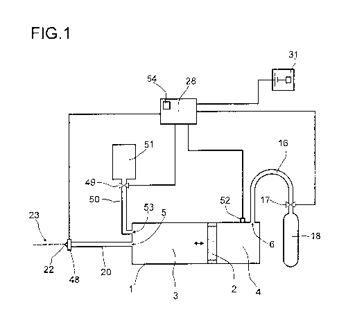
The spray gun comprises a cylinder 1, in which there is formed a fluid chamber
3.
Formed at one end face of the cylinder 1 is a cylinder orifice 53 for filling
the fluid
chamber 3 with fluid. The cylinder orifice 53 is connected to a fluid
reservoir 51 via a
fluid line 50 and a valve 49. The valve 49 is an electrically activatable and
electromagnetically actuable valve which is coupled to a control device 28.
The control
device 28 controls the opening and closing of the valve 49. When the valve 49
is
opened by means of the control device 28, fluid flows from the fluid reservoir
51 into
the fluid chamber 3 via the line 50. When the fluid chamber 3 is completely
full, the
valve 49 is closed again by means of the control device 28.
PF 72523 EP CA 02845485 2014-02-14
19
At the end face of the cylinder 1, the latter has a further cylinder orifice
5, which is
connected to a spray nozzle 22 via a line 20. Formed in the spray nozzle 22 is
a spray
orifice. The spray nozzle is designed such that a fluid jet 23 is created when
a fluid, for
which the spray gun is configured, is pressed under pressure through the spray
nozzle
22.
Arranged immediately upstream of the spray nozzle 22, that is to say at that
end of the
line 20 which is adjacent to the spray nozzle 22, is an electrically
activatable fluid valve
48 for opening and closing the passage from the fluid chamber 3 to the spray
orifice of
the spray nozzle 22. The distance of the spray orifice of the spray nozzle 22
from the
fluid valve 48 is in this exemplary embodiment less than 5 cm, preferably less
than
2 cm. In order to electrically activate the fluid valve 48, the latter is data-
coupled to the
control device 28. By means of a control signal which is generated by the
control
device 28, the fluid valve 48 can be opened for a precisely defined time
interval and
can be closed again after the end of the time interval.
In order to exert a pressure on a fluid located in the fluid chamber 3, the
spray gun
comprises a pressure device. In the exemplary embodiment shown in figure 1, a
piston
2 is mounted movably in the cylinder 1 for this purpose. The cylinder 1 is
subdivided in
a fluid-tight manner by the piston 2 into the fluid chamber 3 for the fluid to
be expelled
and a pressure chamber 4. Provided in the pressure chamber 4 is a further
cylinder
orifice 6, which is connected via a line 16 and a compressed gas valve 17 to a
device
for providing compressed air, for example a compressed air cylinder 18. The
compressed gas valve 17 is also an electrically activatable and
electromagnetically
actuable valve which is data-coupled to the control device 28. The control
device 28
can regulate the pressure in the pressure chamber 4 via the compressed gas
valve 17.
Provided for this purpose in the pressure chamber 4 is a pressure sensor 52,
which
detects the pressure in the pressure chamber 4 and transmits a corresponding
measured value to the control device 28.
Furthermore, an electronic, manually actuable trigger 31 is provided and is
coupled to
the control device 28. By actuating the trigger 31, the user can initiate an
expulsion
operation.
The manner in which the above-described spray gun is calibrated is described
in the
following text:
PF 72523 EP CA 02845485 2014-02-14
First of all, the fluid valve 48 is closed by the control device 28. Then, the
valve 49 is
opened by the control device 28 and a particular fluid of known viscosity is
introduced
into the fluid chamber 3 from the fluid reservoir 51. During this operation,
the piston 2 is
5 moved optionally in the direction of an increase in the volume of the
fluid chamber 3.
Once the fluid chamber 3 has been filled with a particular quantity of fluid,
the valve 49
is closed by the control device 28. Thereupon, the control device 28 generates
a
particular pressure in the pressure chamber 4. For this purpose, the control
device 28
activates the compressed gas valve 17 and checks the pressure in the pressure
10 chamber 4. Optionally, the compressed gas valve 17 can have an outlet
orifice via
which compressed air can be let out of the pressure chamber 4 in order to
lower the
pressure in the pressure chamber 4. This letting out of compressed air via the
outlet
orifice in the compressed gas valve 17 is also controlled by the control
device 28. The
pressure generated in the pressure chamber 4 is transmitted to the fluid,
which is
15 located in the fluid chamber 3, via the movable piston 2. The pressure
is sufficiently
large for the operation of expelling the fluid via the spray nozzle 22.
Subsequently, the fluid valve 48 is opened for a particular time interval by
means of the
control device 28. During this time interval, fluid is expelled from the fluid
chamber 3 via
20 the spray nozzle 22. The expelled fluid is collected and the expelled
volume and/or the
expelled weight are measured. Subsequently, the pressure during the expulsion
operation, the viscosity of the expelled fluid, the length of the time
interval for which the
fluid valve 48 was open, and the volume and/or the weight of the expelled
fluid are
stored in a memory 54 in the control device 28. Optionally, this operation is
repeated at
different pressures and time intervals until the desired parameters for the
expulsion
operation have been set for the fluid having the defined viscosity. These
parameters,
that is to say the viscosity of the fluid, the pressure during the expulsion
operation and
the length of the time interval for the expulsion operation are stored as
setpoint values
in the memory 54 in the control device 28. Moreover, the calibration can be
executed
before each series of expulsions. In this case, storing in a memory is not
necessary.
Optionally, the temperature of the fluid during the expulsion operation can
additionally
be sensed and stored. The calibration can be carried out for fluids of
different
viscosities.
Thus, a pressure and a length of a time interval for the expulsion of a fluid,
for example
a plant protection composition, having a particular viscosity are set in
advance.
PF 72523 EP CA 02845485 2014-02-14
21
In the following text, an exemplary embodiment of the method according to the
invention is described, as is carried out by means of the spray gun described
with
reference to figure 1 following calibration:
As in the calibration operation, the fluid chamber 3 is filled with a
particular fluid volume
from the fluid reservoir 51. The volume in the fluid chamber 3 is in this case
sufficient
for a series of expulsion operations. Subsequently, the valve 49 is closed by
means of
the control device 28. Then, the control device 28 uses the pressure sensor 52
and the
compressed gas valve 17 to regulate the pressure of the compressed air in the
pressure chamber 4 such that it corresponds to the value which was determined
during
the previously carried out calibration operation.
The user now manually actuates the trigger 31. The electronic trigger 31
thereupon
transmits a corresponding control signal to the control device 28. The control
device 28
now checks whether the pressure in the pressure chamber 4 corresponds,
optionally
with a certain tolerance, to the pressure which is stored in the memory 54 and
was set
during the calibration. If the measured actual pressure corresponds to the
stored
setpoint pressure, optionally with a tolerance range being taken into
consideration, the
control device 28 opens the fluid valve 48 precisely for a time interval, the
length of
which is stored in the memory 54 in the control device 28 and was set during
the
calibration. To this end, the control device 28 transmits a corresponding
control signal
to the fluid valve 48. For example, a voltage is applied to the fluid valve 48
for the
length of the time interval. After the end of the time interval, the fluid
valve 48 is closed
again by means of the control device 28. For example, the applied voltage is
set back
to zero so that the fluid valve 48 closes again.
During the time interval for which the fluid valve 48 is open, the fluid
located in the fluid
chamber 3 is expelled as a fluid jet 23 via the spray orifice in the spray
nozzle 22. The
length of the time interval is for example in a range of from 0.5 second to 6
seconds, in
particular in a range of from 1 second to 3 seconds. During this period of
time, the
control device 28 regulates the pressure in the pressure chamber 4 such that
it is
constant, that is to say that a constant pressure is exerted via the piston 2
on the fluid
in the fluid chamber 3.
PF 72523 EP CA 02845485 2014-02-14
22
In the method according to the invention, a gel-like plant protection
composition is
expelled. The plant protection composition is viscoelastic and has a dynamic
viscosity
in a range of from 30 to 1000 mPa.s, frequently in a range of from 30 to 800
mPa.s and
in particular in a range of from 50 to 500 mPa.s (determined by Brookfield's
rotational
viscometry to DIN 53019 (ISO 3219) at 25 C and with a shear gradient of 100 s-
1).
The rheological properties of the formulation of the plant protection
composition are
selected such that they are temperature independent or at least scarcely
temperature
dependent. The rheological properties of the formulation of the plant
protection
composition change within a temperature range of from 15 C to 35 C for example
only
such that the quantity expelled per unit time at a given pressure at a
particular spray
nozzle 22 fluctuates only in a range of +/- 10%, in particular in a range of
+/- 5%.
A second exemplary embodiment of the spray gun according to the invention is
explained in the following text with reference to figure 2:
In the second exemplary embodiment, parts which have the same function as in
the
first exemplary embodiment are designated by the same reference signs. The
function
of these parts is also the same as in the first exemplary embodiment, and
therefore the
description of these parts is not repeated in detail.
The spray gun comprises a piston metering or piston pumping device, which has
a
cylinder 1 and a piston 2 which is mounted movably in the cylinder 1. The
cylinder 1 is
subdivided in a fluid-tight manner by the piston 2 into a fluid chamber 3 for
the fluid to
be expelled and a pressure chamber 4. Provided in the fluid chamber 3 is a
first
cylinder orifice 5, through which the fluid chamber 3 can be filled with fluid
and through
which, moreover, fluid is pressed out of the fluid chamber 3 during the
expulsion
operation. In the pressure chamber 4, a second cylinder orifice 6 is formed in
the
cylinder 1 and is connected to a first connection 7 for a compressed gas line
8, as is
explained later.
Furthermore, in the cylinder 1 there is provided an orifice, through which the
shank 9 of
the piston 2 passes and in which this shank 9 is mounted in a gas-tight manner
in a
bearing 10. Mounting takes place in this case in such a way that the piston 2
can be
moved back and forth in the longitudinal direction of the cylinder 1, so that
the volume
of the fluid chamber 3 and of the pressure chamber 4 is varied as a result of
the
PF 72523 EP CA 02845485 2014-02-14
23
movement of the piston 2. Furthermore, seals are provided in the mounting, so
that no
compressed gas can escape from the pressure chamber 4 through this orifice.
That part of the shank 9 of the piston 2 which passes through the further
orifice in the
cylinder 1 extends into a further cylinder 11. The rear end of the piston 2 is
provided
with a plate 12 which indicates the position of the piston 2 to the user. For
this purpose,
the cylinder 11 is formed in an at least partially transparent manner. In
addition, the
plate 12 serves for coupling the piston 2 to a compression spring 13 which is
coupled
at one end to the plate 12 and at the other end to a terminating wall 15 of
the cylinder
11. The compression spring 13 exerts on the piston 2 a force which acts in the
direction
of a reduction in the volume of the fluid chamber 3.
Furthermore, provided at the rear end of the cylinder 11, near the terminating
wall 15,
is a regulating device which limits the movement of the piston 2 in the
direction of an
increase in the volume of the fluid chamber 3. The maximum volume of the fluid
chamber 3 is thus set by means of the regulating device. In the present
exemplary
embodiment, the regulating device is in the form of a screw 14 which is
received in an
internal thread of the terminating wall 15 of the cylinder 11. By the screw 14
being
rotated in this internal thread, the length of that portion of the screw 14
which extends
into the cylinder 11 can be set. If the piston 2 moves, as is explained later,
in the
direction of the screw 14 during the filling of the fluid chamber 3 with
fluid, this
movement of the piston 2 is limited by an abutment of the plate 12 against the
screw
14.
In order to press the piston 2 in the direction of the first cylinder orifice
5, that is to say
to the left in figure 2, the gas pressure in the pressure chamber 4 is
increased via the
second cylinder orifice 6. In the present exemplary embodiment, compressed air
is
introduced into the pressure chamber 4 via the line 16. The line 16 is
connected to a
compressed gas valve 17, the function of which is explained later.
As in the first exemplary embodiment, a pressure sensor 52 is provided in the
pressure
chamber 4 and is coupled to the control device 28. The air pressure in the
pressure
chamber 4 is increased until the force exerted on the piston 2 by the
compressed air
and, optionally, the compression spring 13 in the direction of the first
cylinder orifice 5
exceeds the force which is exerted on the piston 2 in the opposite direction
by the fluid
located in the fluid chamber 3. It is pointed out that this propulsive
pressure for the
PF 72523 EP CA 02845485 2014-02-14
24
piston 2 may also be exerted only by the compressed gas in the pressure
chamber 4,
only by the compression spring 13 or both by the compressed gas in the
pressure
chamber 4 and by the compression spring 13.
The first cylinder orifice 5 is connected via a line 20 and a fluid valve 21
to a spray
nozzle 22 which provides a spray orifice. The fluid expelled by the spray gun
flows out
through the spray orifice in a fluid jet 23. The pressure exerted on the fluid
may for
example be so high that the emerging fluid jet can be shot onto a target area
over a
distance of two to three meters. The pressure exerted on the fluid may for
example be
in a range of from 2 bar to 6 bar.
As in the first exemplary embodiment, an electrically activatable fluid valve
48, which is
coupled to the control device 28, is arranged directly at the spray nozzle 22.
It can be
opened and closed by a control signal from the control device 28.
The fluid to be expelled is conveyed into the fluid chamber 3 as follows:
Provided for a fluid stock 26 is a fluid reservoir 24 which is connected to a
connection
32 of the spray gun via a line 25. This connection 32 is coupled to a
connection of the
fluid valve 21 which is in the form of a 3/2-way valve. The further
connections of the
3/2-way valve are connected to the first cylinder orifice 5 and to the spray
nozzle 22. In
the first position of the fluid valve 21, a fluid passage from the first
cylinder orifice 5 to
the spray nozzle 22 is provided. However, in a second position of the fluid
valve 21 a
fluid passage from the fluid reservoir 24 via a line 25 through the fluid
valve 21 to the
line 20 and finally to the first cylinder orifice 5 is provided. Thus, in the
second position
of the fluid valve 21, a fluid 26 which is located in the fluid reservoir 24
can be
conveyed into the fluid chamber 3. The fluid 26 can in this case enter the
fluid chamber
3 as a result of gravity or by means of a pump. However, in the present
exemplary
embodiment the fluid reservoir 24 is acted on with compressed air, which
presses the
fluid 26 into the fluid chamber 3. For this purpose, the fluid reservoir 24 is
connected
via a line 8 to a device 18 for the provision of compressed air. The device 18
may for
example be a compressed air tank, a compressor and a hand pump. Furthermore, a
shut-off valve 19 may optionally be arranged in the line 8.
Furthermore, the fluid reservoir 24 is connected via a line 27 to the first
connection 7 of
the compressed gas valve 17, which is also in the form of a 3/2-way valve. In
the first
PF 72523 EP CA 02845485 2014-02-14
position of this compressed gas valve 17, a compressed gas passage from the
compressed air line 8 via the first connection 7 through the compressed gas
valve 17
and the line 16 to the second cylinder orifice 6 into the pressure chamber 4
is provided.
By contrast, in the second position of the compressed gas valve 17, this
passage is
5 closed and a compressed gas passage from the line 16 via a third
connection 33 into
the open is provided. Thus, in the second position, the pressure in the
pressure
chamber 4 can be reduced.
The fluid valve 21 and the compressed gas valve 17 may be electromagnetically
10 actuable. They are connected to the control device 28, which can actuate
them. In this
case, as described above, the valves 17 and 21 can be changed over from the
first
position into the second position, and vice versa. For this purpose, the
control device
28 may comprise for example a relay or a microprocessor.
15 Furthermore, the control device 28 is connected to a sensor 29. The
sensor 29 may for
example be in the form of a reed switch or comprise a reed contact. This
contact is
closed when the field strength of a magnetic field at the sensor 29 exceeds a
limit
value. The control device 28 detects whether the reed contact of the sensor 29
is
closed or open.
The position of the piston 2 in the cylinder 1 can be detected by means of the
sensor
29. In the spray gun according to the invention, a particular position of the
piston 2
within the cylinder 1, in which position the expulsion operations are intended
to be
ended, is defined. The sensor 29 changes its state precisely in this defined
position of
the piston 2. This is detected by the control device 28. In order to bring
about this
change of state of the sensor 29, a permanent magnet 30 is integrated in the
piston 2.
This permanent magnet 30 generates a magnetic field, the field strength of
which at the
location of the sensor 29 depends on the position of the piston 2. If the
piston 2 is in the
defined position explained above, the magnetic field generated by the
permanent
magnet 30 causes a change of state in the sensor 29.
The filling of the fluid chamber 3 and the fluid expulsion in the second
exemplary
embodiment of the spray nozzle are explained in detail in the following text:
When the fluid chamber 3 is being filled with fluid, both the fluid valve 21
and the
compressed gas valve 17 are in the second position. In this case, the fluid 26
in the
PF 72523 EP CA 02845485 2014-02-14
26
fluid reservoir 24 is conveyed through the line 25 and through the fluid valve
21 via the
line 20 into the fluid chamber 3 of the cylinder 1. The pressure exerted by
the
compressed air is in this case so high that the piston 2 is moved to the right
in figure 2,
specifically counter to the force which is exerted by the compression spring
13. During
the movement of the piston 2, the air in the pressure chamber 4 escapes
outward
through the line 16, the compressed gas valve 17 and the third connection 33.
The fluid
chamber 3 can be filled with fluid, with the volume of the fluid chamber 3
increasing as
a result of the movement of the piston 2, until the plate 12 of the piston 2
butts against
the screw 14. When the piston 2 is at this stop, the maximum set volume of the
fluid
chamber 3 is reached and the fluid chamber 3 is completely filled with fluid.
If the trigger 31 is now actuated by a user, a corresponding signal is
transmitted to the
control device 28. The control device 28 thereupon switches the compressed gas
valve
17 and the fluid valve 21 into the first position. In this position, the fluid
supply from the
fluid reservoir 24 is shut off, but the fluid passage from the fluid chamber 3
to the fluid
valve 48 is open. Moreover, at the same time or preferably shortly beforehand,
the
compressed gas passage from the compressed air line 8 into the pressure
chamber 4
is opened, so that compressed air is introduced into the pressure chamber 4.
As in the first exemplary embodiment, the control device 28 now regulates the
pressure
in the pressure chamber 4 such that it corresponds to the value which was
determined
during the calibration and is stored in the memory 54 in the control device
28. If the
actual pressure measured corresponds to the stored setpoint pressure, the
control
device 28 uses a control signal to open the fluid valve 48 for a time
interval, the length
of which is stored in the memory 54 in the control device 28 and which was
determined
previously during the calibration. After the end of the time interval, the
fluid valve 48 is
closed again by means of the control device 28. For the length of the time
interval, a
fluid jet 23 was expelled during the expulsion operation.
In this way, a plurality of expulsion operations can now be carried out. In
this case, the
piston 2 moves in the direction of a reduction in the volume of the fluid
chamber 3.
When the piston 2 now reaches the defined position explained above, the
permanent
magnet 30 generates at the sensor 29 a magnetic field having a field strength
which
leads to a change of state of the sensor 29. Such a change of state is
detected by the
control device 28, whereupon the control device 28, after the conclusion of
the
PF 72523 EP CA 02845485 2014-02-14
27
expulsion operation and after the closure of the fluid valve 48, switches the
fluid valve
21 and the compressed gas valve 17 in each case back into the second position
again.
The changeover of the two valves 17 and 21 may take place simultaneously.
Furthermore, it is possible for the fluid valve 21 to be changed over first,
and only
shortly thereafter the compressed gas valve 17.
Once the two valves 17 and 21 have been moved into the second position, the
fluid
chamber 3 is automatically filled with fluid again for the next expulsion
operations, as
explained above.
The third exemplary embodiment of the spray gun according to the invention is
explained in the following text with reference to figure 3:
In the third exemplary embodiment, parts which have the same function as in
the first
and second exemplary embodiments are designated by the same reference signs.
The
function of these parts is also the same as in the first and/or second
exemplary
embodiment, and therefore the description of these parts is not repeated in
detail.
The third exemplary embodiment of the spray gun differs from the second
exemplary
embodiment in particular in that the pressure chamber 4 of the second
exemplary
embodiment has been converted into a second fluid chamber 34. A first fluid
chamber
3 and a second fluid chamber 34, which are separated from one another by the
movable piston 2, are thus formed in the cylinder 1. Furthermore, the
compression
spring 13 of the second exemplary embodiment has been omitted.
As in the second exemplary embodiment, the first fluid chamber 3 is connected
via the
first cylinder orifice 5 and a line 20 to a fluid valve 21 which is designated
as a first fluid
valve 21 in this third exemplary embodiment. The first fluid valve 21, too, is
in the form
of a 3/2-way valve. As in the second exemplary embodiment, a connection of the
first
fluid valve 21 is connected to the spray nozzle 22. However, in the third
exemplary
embodiment a third fluid valve 35 is arranged between the connection of the
first fluid
valve 21 and the spray nozzle 22, as is explained later.
As in the second exemplary embodiment, the connection 32 of the first fluid
valve 21 is
connected to a fluid reservoir 24 in which fluid 26 is located. As in the
second
exemplary embodiment, the fluid reservoir 24 can be acted on with compressed
air by
PF 72523 EP CA 02845485 2014-02-14
28
means of the compressed air line 8, the shut-off valve 19 and the device 18
for the
provision of compressed air. However, in all the exemplary embodiments, the
fluid may
also be put under pressure in another way, in order to move the piston 2, as
explained
later. For example, a pump may be used. In this case, there may also be
provided a
bypass, via which the fluid passes back into the reservoir when the cylinder 1
is not
filled, because at least one fluid valve or a plurality of fluid valves is or
are closed.
Unlike in the second exemplary embodiment, in the third exemplary embodiment
the
second cylinder orifice 6, which in this case is arranged at the second fluid
chamber 34,
is connected to a second fluid valve 36 via the line 16. This second fluid
valve, too, is
designed as a 3/2-way valve. The connection 37 of the second fluid valve 36 is
connected to the fluid reservoir 24 via a line 38. The other connection 41 of
the second
fluid valve 36 is connected to the spray nozzle 22 via the third fluid valve
35.
The third fluid valve 35 is in the form of a 3/3-way valve with a shut-off
middle position.
A passage from the line 39 to the spray nozzle 22 or from the line 40 to the
spray
nozzle 22 can thus be produced. Furthermore, both passages may be shut off.
As in the second exemplary embodiment, a sensor 29 in the form of a reed
switch is
arranged in the first fluid chamber 3 and is designated as a first sensor 29
in the third
exemplary embodiment. If the permanent magnet 30 of the piston 2 is in the
defined
position explained with regard to the second exemplary embodiment, this
permanent
magnet 30 generates a magnetic field, the field strength of which at the
location of the
first sensor 29 causes the reed contact to be closed. This is detected by the
control
device 29.
However, in the third exemplary embodiment, in contrast to the second
exemplary
embodiment, a corresponding second sensor 39 is located in the second fluid
chamber
34. The second sensor 39, too, comprises a reed contact. In the spray gun of
the third
exemplary embodiment there is defined a further position of the piston 2, in
which the
expulsion operation is intended to be ended, specifically, in this case, the
operation of
expelling the fluid out of the second fluid chamber 34. The second sensor 39
is
designed such that the reed contact is closed when the permanent magnet 30 of
the
piston 2 generates, in a correspondingly defined position, a magnetic field,
the field
strength of which at the location of the second sensor 39 exceeds the limit
value for
,
PF 72523 EP CA 02845485 2014-02-14
29
switching the reed contact. This change of state of the second sensor 39 is
also
detected by the control device 28.
Furthermore, the two sensors 29, 39 may be adjustable in the longitudinal
direction of
the cylinder 1. In this case, the fluid volume to be discharged can be adapted
by the
position of the sensors 29, 39 being changed.
Furthermore, the spray gun of the third exemplary embodiment, too, has a fluid
valve
48 directly at the spray nozzle 22, said fluid valve 48 being electrically
activatable by
the control device 28. Furthermore, in each of the two fluid chambers 3 and 34
there is
arranged a pressure sensor (not shown), which measures the pressure in each
fluid
chamber 3, 34 and transmits it to the control device 28.
The spraying operation with the spray gun according to the third exemplary
embodiment is explained in the following text:
Before the actual spraying operation, the cylinder 1 of the spray gun is
filled with fluid
26 from the fluid reservoir 24. In this initial state, the control device 28
first activates the
third fluid valve 35 such that the passages in the direction of the spray
nozzle 22 are
shut off, that is to say the third fluid valve 35 is in the middle position.
Furthermore, the
fluid valve 48 is closed. Thereupon, the first fluid valve 21 is activated by
the control
device 28 such that a fluid passage from the fluid reservoir 24 into the first
fluid
chamber 3 is created. If the shut-off valve 19 is now opened, the fluid
reservoir 24 is
acted on with compressed air, so that fluid 26 flows via the line 25 through
the first fluid
valve 21 into the first fluid chamber 3. Alternatively, in this case, too, the
fluid may be
put under pressure, for example by means of a pump. Thus, in the illustration
according to figure 3, the piston 2 is moved to the right until it butts
against a stop (not
illustrated). lf, in this case, air is still located in the second fluid
chamber 34, an outlet
valve for displacing this air may be provided. If fluid 26 is already located
in the second
fluid chamber 34, the second fluid valve 36 is activated by the control device
28 such
that the fluid passage between the line 38 and the line 16 is opened, so that
the fluid in
the second fluid chamber 34 can flow back into the reservoir 24.
If the trigger 31 is now actuated by a user, the control device 28 switches
the first fluid
valve 21 for a fluid passage from the line 20 into the line 39. The fluid
passage from the
line 20 into the line 25 is shut off. By contrast, the second fluid valve 36
is switched
PF 72523 EP CA 02845485 2014-02-14
such that the fluid passage from the line 38 into the line 16 is opened, but
the fluid
passage from the line 16 into the line 40 is shut off. Furthermore, the
control device 28
activates the third fluid valve 35 such that the fluid passage from the line
39 to the fluid
valve 48 is opened, but the fluid passage from the line 40 to the fluid valve
48 is shut
5 off. This switching of the three fluid valves 21, 36 and 35 has the
effect that, by the fluid
reservoir 24 being acted on with compressed air, fluid 26 flows via the line
38 through
the second fluid valve 36 into the second fluid chamber 34. The fluid in the
second fluid
chamber 34 exerts a force on the piston 2 so that the latter is pressed in the
direction of
a reduction in the volume of the first fluid chamber 3, to the left in the
illustration
10 according to figure 3. The fluid located in the first fluid chamber 3 is
thus pressed
through the first cylinder orifice 5 via the line 20, through the first fluid
valve 21 via the
line 39 and through the third fluid valve 35 to the fluid valve 48.
lf, as in the first two exemplary embodiments, the pressure exerted on the
fluid now
15 corresponds to the setpoint value stored in the control device 28, the
control device 28
opens the fluid valve 48 for the previously set time interval, the length of
which is stored
in the memory 54 in the control device 28, and the fluid is expelled as a
fluid jet 23.
Such an expulsion operation can be repeated until the magnetic field generated
by the
permanent magnet 30, at the location of the first sensor 29, exceeds a field
strength
20 which brings about a change of state of the first sensor 29, said change
of state being
detected by the control device 28. As soon as this change of state has been
detected,
the control device 28 changes over the three fluid valves 21, 36 and 35, after
the
conclusion of the last expulsion operation, as follows: the first fluid valve
21 is switched
such that the passage from the line 20 to the line 39 is shut off, but the
passage from
25 the line 25 to the line 20 is opened. The second fluid valve 36 is
changed over such
that the fluid passage from the line 38 into the line 16 is shut off, but the
fluid passage
from the line 16 into the line 40 is opened. Furthermore, the third fluid
valve 35 is
changed over such that it is moved into the completely shutting-off middle
position or
such that it is moved directly into a position in which the fluid passage from
the line 40
30 to the spray nozzle 22 is opened, but the fluid passage from the line 39
to the spray
nozzle 22 is shut off. When the defined position of the piston 2 has been
detected, at
least the first fluid valve 21 or the third fluid valve 35 for the passage
from the first fluid
chamber 3 to the spray nozzle 22 is shut off.
This changing over of the three fluid valves 21, 36, 35 has the effect that
the fluid 26
now flows the other way round under pressure via the line 25, through the
first fluid
PF 72523 EP CA 02845485 2014-02-14
31
valve 21 into the first fluid chamber 3. Here, the fluid exerts a force upon
the piston 2
so that the latter is moved in the direction of a reduction in the volume of
the second
fluid chamber 34, to the right in the illustration according to figure 3. The
first fluid
chamber 3 is now filled. However, as a result of this filling, the fluid
located in the
second fluid chamber 34 is pressed via the line 16, through the second fluid
valve 36,
via the line 40, through the third fluid valve 35, to the fluid valve 48.
A series of expulsion operations of the fluid located in the fluid chamber 34
can now
again take place. These expulsion operations last until the magnetic field
generated by
the permanent magnet 30 at the location of the second sensor 39 reaches a
field
strength which causes a change of state of the second sensor 39. As soon as
such a
change of state has been detected by the control device 28, after the
conclusion of the
last expulsion operation, the fluid valves 21, 36 and 35 are switched back
again, as
explained above, so that subsequently the second fluid chamber 34 is filled.
The fluid is expelled from the spray gun of the third exemplary embodiment, as
in the
spray gun of the first or second exemplary embodiment, as a fluid jet 23 which
has a
constant expulsion velocity up to the end of the expulsion operation, so that
the fluid jet
23 reaches its target completely. Moreover, the fluid valve 48 prevents fluid
from
dripping.
The fourth exemplary embodiment of the spray gun according to the invention is
explained in the following text with reference to figure 4:
In the fourth exemplary embodiment, parts which have the same function as in
the
preceding exemplary embodiments are designated by the same reference signs.
The
function of these parts is also the same as in the preceding exemplary
embodiments,
and therefore the description of these parts is not repeated in detail.
The basic functioning of the spray gun of the fourth exemplary embodiment
corresponds to the spray gun of the third exemplary embodiment. However, in
this
case a single cylinder 1 comprising two fluid chambers 3 and 34 which are
separated
by the piston 2 is not provided, but rather two cylinders 1-1 and 1-2 are
provided.
However, the functional principle corresponds substantially to the functional
principle of
the spray gun of the third exemplary embodiment.
PF 72523 EP CA 02845485 2014-02-14
32
A first fluid chamber 3-1 having a first cylinder orifice 5-1 is formed in the
first cylinder
1-1. Furthermore, a first pressure chamber 4-1 is formed in the first cylinder
1-1. A
movable first piston 2-1 is arranged between the first fluid chamber 3-1 and
the first
pressure chamber 4-1.
Correspondingly, a second fluid chamber 3-2 with a second cylinder orifice 5-2
is
formed in the second cylinder 1-2. A second pressure chamber 4-2 is formed in
the
second cylinder 1-2, too, a movable second piston 2-2 being arranged between
the
second fluid chamber 3-2 and the second pressure chamber 4-2. The first
pressure
chamber 4-1 and the second pressure chamber 4-2 communicate with one another
via
a line 42. A non-compressible working fluid, such as oil, for example, is
located in the
first and the second pressure chamber 4-1, 4-2 and the line 42. Furthermore,
the line
42 may be connected to a reservoir 43 for the working fluid. The volume of the
working
fluid in the two pressure chambers 4-1, 4-2 and the line 42 can be varied via
the
reservoir 43. The maximum volume of the two fluid chambers 3-1, 3-2 and
consequently the expelled fluid volume can be set in this Way.
Alternatively or in addition, as in the spray gun of the third exemplary
embodiment, the
two sensors 29-1, 29-2 may be adjustable in the longitudinal direction of the
cylinder
1-1, 1-2, so that the fluid volume to be discharged can be adapted by the
position of the
sensors 29-1, 29-2 being varied.
The working fluid transmits a force exerted by the first piston 2-1 to the
second piston
2-2, and vice versa. The unit formed from the first piston 2-1, the working
fluid and the
second piston 2-2 thus corresponds to the piston 2 of the spray gun of the
third
exemplary embodiment.
The spray gun of the fourth exemplary embodiment comprises two fluid valves 44
and
45. The fluid valve 44 is also designated as first fluid valve 44 in the
following text.
Since the fluid valve 45 corresponds functionally to the third fluid valve 35
of the third
exemplary embodiment, this fluid valve 45 is also designated as third fluid
valve 45 in
the following text.
The first cylinder orifice 5-1 of the first fluid chamber 3-1 is connected via
a line 46 to a
connection of the first fluid valve 44 and of the third fluid valve 45.
Furthermore, the
second cylinder orifice 5-2 of the second fluid chamber 3-2 is connected via a
line 47 to
PF 72523 EP CA 02845485 2014-02-14
33
another connection of the first fluid valve 44 and to another connection of
the third fluid
valve 45. A further connection of the first fluid valve 44 is coupled via a
line 25 to the
fluid reservoir 24 in which the fluid 26 is located. As in the first exemplary
embodiments, the fluid reservoir 24 is coupled via a compressed air line 8 and
an
optional shut-off valve 19 to a device 18 for the provision of compressed air.
However,
it would also be possible to put the fluid under pressure directly, for
example by means
of a pump. The first fluid valve 44 is activated by the control device 28. In
one state of
the first fluid valve 44, a passage from the line 25 to the line 46 is
provided, the
passage from the line 25 to the line 47 being shut off. In the other state, a
passage
from the line 25 to the line 47 is provided, the passage from the line 25 to
the line 46
being shut off.
The spray gun of the fourth exemplary embodiment, too, has a fluid valve 48
directly at
the spray nozzle 22, said fluid valve 48 being electrically controlled by
means of the
control device 28. Furthermore, pressure sensors (not shown), which are
coupled to
the control device 28 are provided at the pressure chambers 4-1 and 4-2.
The third fluid valve 45 is activated by the control device 28, with in one
state a
passage from the line 46 to the fluid valve 48 being opened, whereas the
passage from
the line 47 to the fluid valve 48 is shut off. In another state, the passage
from the line
46 to the fluid valve 48 is shut off, whereas the passage from the line 47 to
the fluid
valve 48 is opened. Furthermore, as in the spray gun of the third exemplary
embodiment, there is provided a middle position, in which both passages to the
fluid
valve 48 are shut off.
Similarly to the spray guns of the preceding exemplary embodiments, a first
sensor 29-
1 is provided for the first cylinder 1-1 in the first fluid chamber 3-1 and
detects the
position of the first piston 2-1 on account of a magnetic field generated by a
first
permanent magnet 30-1. Likewise, a second sensor 29-2 is provided in the
second
fluid chamber 3-2 of the second piston 1-2 and detects the position of the
second
piston 2-2, in that, as explained with regard to the third exemplary
embodiment, a
change of state of the second sensor 29-2 is detected by means of the field
strength of
a magnetic field generated by a second permanent magnet 30-2 which is arranged
at
the second piston 2-2. As in the spray gun of the third exemplary embodiment,
the
signals of the two sensors 29-1 and 29-2 are transmitted to the control device
28,
which activates the two fluid valves 44 and 45 depending on these signals.
PF 72523 EP CA 02845485 2014-02-14
34
A spraying operation which is carried out by the spray gun of the fourth
exemplary
embodiment is explained in the following text:
As in the preceding exemplary embodiments, fluid expulsion is initiated in
that a user
actuates the trigger 31, which is connected to the control device 28.
First of all, the control device 28 activates the first fluid valve 44 such
that a fluid
passage from the line 25 to the line 46 is provided, so that the first fluid
chamber 3-1
can be filled with fluid 26. The third fluid valve 45 is first of all located
in the middle
position in which the two passages are shut off. The first fluid chamber 3-1
is filled with
fluid, as a result of which the piston 2-1 is moved to the right in the
illustration
according to figure 4, so that the volume of the first fluid chamber 3-1
increases. At the
same time, on account of the transmission of force by the working fluid, the
second
piston 2-2 moves to the left in the illustration according to figure 4, in the
direction of a
reduction in the volume of the second fluid chamber 3-2. If air is still
located in the
second fluid chamber 3-2 when the spray gun is put into operation, an outlet
valve (not
shown) may be provided for this air. The first piston 2-1 is moved in the
direction of an
increase in the volume of the first fluid chamber 3-1 until the first piston 2-
1 butts
against a stop which may be provided by a cylinder wall or, as in the spray
gun of the
second exemplary embodiment, by an adjusting screw. The control device 28
subsequently changes over the first fluid valve 44 such that a fluid passage
from the
line 25 into the line 47 is provided. Furthermore, the third fluid valve 45 is
switched
such that a fluid passage from the line 46 to the spray nozzle 22 is opened.
By the action of pressure on the fluid reservoir 24, the fluid 26 is now
pressed through
the first fluid valve 44 and the line 47 into the second fluid chamber 3-2.
Alternatively,
as in the spray gun of the third exemplary embodiment, the fluid may also be
put under
pressure, for example, by means of a pump. As a result, the second piston 2-2
is
moved in the direction of an increase in the volume of the second fluid
chamber 3-2. At
the same time, on account of the communication between the two pressure
chambers
4-1 and 4-2, the first piston 2-1 is moved in the direction of a reduction in
the volume of
the first fluid chamber 3-1, as a result of which fluid is pressed out of the
first fluid
chamber 3-1 via the line 46, through the third fluid valve 45 to the fluid
valve 48.
PF 72523 EP CA 02845485 2014-02-14
Now, as in the second and the third exemplary embodiment, the fluid valve 48
can be
opened for the previously set time interval defined during the calibration, in
order to
expel the fluid as a fluid jet 23. The expulsion operations can be repeated
until the first
piston 2-1 has reached the defined position, this being sensed by the first
sensor 29-1,
5 as explained above. Following the conclusion of the last expulsion
operation, the
control device 28 then switches the third fluid valve 45 in such a way that
the fluid
passage from the line 46 to the fluid valve 48 is shut off. The third fluid
valve 45 is in
this case moved in particular into the completely shutting-off middle
position.
Thereupon, the first fluid valve 44 is changed over, so that a fluid passage
from the line
10 25 to the line 46 is opened. The third fluid valve 45 is now moved into
a position in
which a passage from the line 47 to the fluid valve 48 is provided. By the
action of
pressure on the fluid reservoir 24, fluid 26 is now pressed through the first
fluid valve
44 and the line 46 into the first fluid chamber 3-1. As a result, the first
piston 2-1 is
moved in the direction of an increase in the volume of the first fluid chamber
3-1. At the
15 same time, the second piston 2-2 is moved in the direction of a
reduction in the volume
of the second fluid chamber 3-2, as a result of which the fluid located in the
second
fluid chamber 3-2 is pressed through the line 47 and through the third fluid
valve 45 to
the fluid valve 48. Subsequently, a new series of expulsion operations can
begin.
20 In the above-described four exemplary embodiments, it is furthermore
possible not to
use a memory 54. Instead, the pressure exerted on the fluid in the fluid
chamber 3,
said pressure having previously been set, can be adjusted or regulated
mechanically
by means of a pressure valve, by means of a pump, for example via the
regulation of
the rotational speed of the pump, or by means of other techniques which are
known per
25 se.
A fifth exemplary embodiment of the spray gun according to the invention is
explained
in the following text with reference to figure 5:
30 In the fifth exemplary embodiment, parts which have the same function as
in the
preceding exemplary embodiments are designated by the same reference signs.
The
function of these parts is also the same as in the preceding exemplary
embodiments,
and therefore the description of these parts is not repeated in detail.
35 The fifth exemplary embodiment is similar to the first exemplary
embodiment. However,
in this case the fluid chamber 3 is not formed by a cylinder but by a line,
which, as
PF 72523 EP CA 02845485 2014-02-14
36
shown in figure 5, is immersed in the fluid located in the fluid reservoir 51.
The fluid is
located at the bottom of the fluid reservoir 51 and an air reservoir which is
closed off in
a gas-tight manner is located above the surface of the fluid. This air
reservoir is
connected to a pressure chamber 4 via a pressure line 58. The pressure chamber
4 is
connected in turn, as in the first exemplary embodiment, to a compressed air
cylinder
18 via a line 16 and a compressed gas valve 17. The compressed gas valve 17 is
controlled by the control device 28 such that a constant previously set
pressure is
exerted on the fluid located in the fluid reservoir 51. This ensures that a
pressurized
fluid is always located in the fluid chamber 3 which is in the form of a line.
As in the first exemplary embodiment, the fluid valve 48, which is activated
via the
control device 28, is provided directly upstream of the spray nozzle 22.
Provided in this
case in the control device 28 is a timer, which determines the opening time of
the fluid
valve 48 during the expulsion of the fluid jet 23. As in the first exemplary
embodiment,
following the actuation of the trigger 31 by means of the control device 28
the fluid
valve 28 is opened for a previously set time interval and a defined volume or
a defined
weight of the fluid is expelled through the spray nozzle 22.
A sixth exemplary embodiment of the spray gun according to the invention is
explained
in the following text with reference to figure 6:
In the sixth exemplary embodiment, parts which have the same function as in
the
preceding exemplary embodiments are designated by the same reference signs.
The
function of these parts is also the same as in the preceding exemplary
embodiments,
and therefore the description of these parts is not repeated in detail.
The structure of the sixth exemplary embodiment of the spray gun is similar to
the
structure of the fifth exemplary embodiment of the spray gun. However, in this
case a
fluid pump 56 is arranged between the fluid chamber 3 in the form of a line
and the fluid
reservoir 51. A device for the provision of compressed air is not required in
this case.
That end of the fluid chamber 3 which is remote from the fluid valve 48 is
adjoined by
the fluid pump 56, which is connected to the fluid reservoir 51 via the line
57. By means
of the fluid pump 56, the fluid located in the fluid reservoir 51 is pumped
out and
pumped into the fluid chamber 3. Furthermore, there may be provided a bypass,
via
which the fluid can pass back into the fluid reservoir 51 if the pressure
exerted on the
PF 72523 EP CA 02845485 2014-02-14
37
fluid is too high. The fluid pump 56 is electrically coupled to the control
device 28 so
that it can be activated by the control device 28. Activation takes place such
that a
constant pressure is always exerted on the fluid located in the fluid chamber
3. For this
purpose, for example the rotational speed of the fluid pump can be regulated.
The expulsion operation then takes place in the same manner as in the fifth
exemplary
embodiment.
The spray guns of the second to sixth exemplary embodiments and the methods
implemented by these spray guns are carried out in particular with the plant
protection
compositions which were mentioned initially and with reference to the first
exemplary
embodiment.
In the above-described exemplary embodiments, the fluid valve 48 is arranged
directly
at the spray orifice 22. In a further, seventh exemplary embodiment,
experiments were
carried out to study what effect the distance of the fluid valve 48 from the
spray orifice
22 has on the dripping behavior at the nozzle when fluids having different
viscosities
are expelled.
The structure of the seventh exemplary embodiment corresponds to the structure
of the
first exemplary embodiment, apart from the distance of the fluid valve 48 from
the spray
orifice 22.
The fluid valve 48 was connected to the spray nozzle 22 via a flexible tube.
The outside
diameter of the flexible tube was 8 mm and the inside diameter was 6 mm. A
Lechler
544.320 full-jet nozzle was used as the nozzle.
The spray nozzle 22, in which the spray orifice is formed, was positioned 10
cm over
an application area, which takes up a path length of 120 cm. In addition, the
spray
nozzle 22 was oriented such that the application jet likewise projects 10 cm
beyond the
application area at the end of the path. In order to measure the loss of fluid
during the
expulsion operation on the application area, previously tared paper was laid
out. The
test was then carried out as follows: after a fluid reservoir had been filled,
the system
was conditioned with the substance to be tested, i.e. a fluid having a
particular viscosity
was filled into the fluid reservoir. Next, in order to avoid errors, the spray
nozzle 22 was
dabbed dry directly prior to the first application. Each part of the test
consists of three
PF 72523 EP CA 02845485 2014-02-14
38
applications, which were carried out at a spraying pressure of 3 bar. Each
application
lasted 1.5 seconds. In order to allow for possible dripping, 8.5 seconds were
waited
between each discharge. At the end, the residual fluid from the spray nozzle
22 was
absorbed using the paper and weighed.
The test results are given in the following table:
Starting material Flexible tube Amount Observations
BAS Water Visco- Type Length from 3 Application
route Nozzle mouth
310 sity applica-
63 I tions [g1
1 3 123.8 Festo 8 0 cm 0.03 localized very No
dripping at
mPa.s small droplets on the nozzle
the path
1 2 215.2 Festo 8 0 cm 0.00 localized very No
dripping at
mPa.s small droplets on the nozzle
the path
1 1 579.0 Festo 8 0 cm 0.01 localized very No
dripping at
mPa.s small droplets on the nozzle
the path
1 3 123.8 Festo 8 50 cm 0.17 Some drops Drips
a little
mPa.s discernible
1 2 215.2 Festo 8 50 cm 0.23 Some drops Drips
a little
mPa.s discernible
1 1 579.0 Festo 8 50 cm 0.45 Some drops Drips
a little
mPa.s discernible
1 3 123.8 Festo 8 100 cm 0.34 Increased Drips at the
mPa.s number of drops nozzle
seen on the path
1 2 215.2 Festo 8 100 cm 0.41 Increased Drips at the
mPa.s number of drops nozzle
seen on the path
1 1 579.0 Festo 8 100 cm 0.60 Increased Drips at the
mPa.s number of drops nozzle
seen on the path
Figure 7 illustrates the relationship of the fluid loss depending on the
mixing ratio
between the active substance and water, i.e. the viscosity of the fluid, and
the distance
between the spray nozzle 22 and the fluid valve 28.
PF 72523 EP CA 02845485 2014-02-14
39
It has been found in tests that the application time has no effect on the
fluid loss, since,
as soon as the spray jet has been built up, no drops deviate from the target.
However,
when the spray jet is being built up and particularly when it is being broken
down, drops
could be registered on the application path. In addition, there is dripping at
the nozzle
opening. The results of the tests show greater loss with an increasing "dead
volume"
between the valve 48 and the spray nozzle 22, i.e. with a greater distance
between the
valve 48 and the spray nozzle 22. In particular at a distance of more than 50
cm, an
undesired fluid loss arises. In this case, the loss is greater on the
application route, the
greater the viscosity of the fluid, i.e. the spray liquor, is. The consistency
of the
formulation thus also has a great influence on the fluid loss. A possible
explanation for
this is that the more viscous fluid absorbs more energy, which has to be
released again
after the fluid valve 48 is closed. This results in dripping. A further
indication therefor
was a required steeper incidence angle of the spray nozzle 22 for more viscous
fluids.
This steeper incidence angle was required in order to reach the target.
In preliminary tests, it was moreover found that tapering of the flexible tube
between
the spray nozzle 22 and the fluid valve 48 results in smaller losses. An
increase in the
pressure results in an increased fluid loss on the path from the spray nozzle
22 to the
target. However, fluid losses can be largely ruled out when a "dead volume"
from the
fluid valve 48 to the spray nozzle 22 is avoided, i.e. when the spray nozzle
22 is
arranged directly at the fluid valve 48.
PF 72523 EP CA 02845485 2014-02-14
List of reference signs:
1 Cylinder
1-1 First cylinder
5 1-2 Second cylinder
2 Piston
3 Fluid chamber; first fluid chamber
3-1 First fluid chamber
3-2 Second fluid chamber
10 4 Pressure chamber
4-1 First pressure chamber
4-2 Second pressure chamber
5 Cylinder orifice, first cylinder orifice
5-1 First cylinder orifice
15 5-2 Second cylinder orifice
6 Cylinder orifice, second cylinder orifice
7 First connection
8 Compressed air line
9 Shank of piston 2
20 10 Bearing
11 Cylinder
12 Plate
13 Compression spring
14 Screw
25 15 Terminating wall
16 Line
17 Compressed gas valve
18 Device for the provision of compressed air, compressed air
cylinder
,
19 Shut-off valve
30 20 Line
21 Fluid valve; first fluid valve
22 Spray nozzle
23 Fluid jet
24 Fluid reservoir
35 25 Line
PF 72523 EP CA 02845485 2014-02-14
41
26 Fluid
27 Line
28 Control device
29 Sensor; first sensor
30 Permanent magnet
31 Trigger
32 Second connection
33 Third connection
34 Second fluid chamber
35 Third fluid valve
36 Second fluid valve
37 Connection
38 Line
39 Line
40 Line
41 Connection
42 Line
43 Reservoir
44 Fluid valve; first fluid valve
45 Fluid valve; third fluid valve
46 Line
47 Line
48 Fluid valve
49 Fluid valve
50 Fluid line
51 Fluid reservoir
52 Pressure sensor
53 Cylinder orifice
54 Memory
55 Timer
56 Fluid pump
57 Line
58 Compressed gas line