Note: Descriptions are shown in the official language in which they were submitted.
CA 02845823 2014-02-18
1
WET QUENCHING TOWER FOR QUENCHING HOT COKE
Description:
The invention relates to a wet quenching tower for quenching hot
coke, with a quenching chamber, with a quenching shower unit
above the quenching chamber for the discharge of quenching
water, with a chimney placed onto the quenching chamber and with
at
least one vertical-throughf low separation device which is
arranged horizontally or at an oblique angle to the vertical and
which has a multiplicity of lamellae, each with a branch-free
cross section, flow paths being formed in each case between two
adjacent lamellae.
Wet quenching towers are used for cooling still hot coke
directly after the coking process and for avoiding a burn-off of
the hot coke. For this purpose, the coke is dumped from the
furnace aperture into a quenching trolley and is then brought to
the wet quenching tower by means of the quenching trolley. In
the wet quenching tower, the hot coke is sprayed with water with
the aid of the quenching shower unit, as a result of which a
very large quantity of steam is immediately formed which is also
designated as quenching vapor. On account of the abrupt cooling
and the increase in volume due to the evaporation of the water,
large quantities of dust are also generated and are entrained
upward together with the quenching vapors.
Both the consumption of water and the emission of dust particles
constitute, in practice, decisive factors in terms of wet
quenching efficiency and environmental pollution. So that as
CA 02845823 2014-02-18
2
large a fraction of quenching water as possible can be recovered
and thus as large a fraction of dust particles as possible can
be separated, throughflow separation devices are arranged in the
chimney placed onto the quenching chamber. In this case, it must
be remembered that water drops, on the one hand, and dust
particles, on the other hand, because of different size
distribution and different specific gravity, also have different
properties as regards their separability. In order to separate
water drops, flow paths are provided which have a change in
direction. The water drops, which are heavier than air, cannot
follow such a change in direction and are correspondingly
deposited on walls of the separation device. By contrast, so
that dust particles can also be separated, in the known wet
quenching towers special measures are provided which, for
example, cause a swirling of the flow at the separation device.
In order to enable dust to be separated, according to
DE 2 100 848 C a wet quenching tower with a separation device is
known, the separation device having essentially planar lamellae
with an end nose.
A wet quenching tower having the features initially described is
known from DE 40 11 431 Al. On the basis of a wet quenching
tower with a separation device according to DE 2 100 848 C, a
configuration of the lamellae in the form of angular profiles is
proposed. The combination of angling with an end nose is
intended to achieve good separation of both dust and water
drops. There is the disadvantage, however, that complete
cleaning is difficult particularly in the region of the nose.
Furthermore, the separation capacity with regard to water drops
also still needs to be improved.
- ,
CA 02845823 2014-02-18
3
DE 101 138 90 Cl and DE 101 225 31 Al disclose wet quenching
towers which in each case have a plurality of separation devices
for improving the separation capacity. Here, too, simply angled
lamellae are provided, which have at their ends noses or
branches with a T-shaped profile. This shaping of the profile of
the lamellae serves for further reducing the immission of solids
during the quenching of coke. In order particularly to increase
the separation of dust, a turbulent flow is to be generated. In
this case, however, there is the disadvantage that the flow
resistance is increased greatly by the separation devices, while
the turbulence-generating structures are also difficult to
clean.
Finally, DE 30 46 313 Al discloses a wet quenching tower in
which the flow passes through the separation device
horizontally. The individual lamellae have in cross section a
branch in the form of a fin which forms a capture chamber open
opposite to the flow direction. Such a shape of the lamellae is
unsuitable for vertical-throughf low separation devices, because
then, in the region of the branches, cleaning and a removal of
deposited dust are possible only with great difficulty.
Against this background, the object on which the invention is
based is to specify a wet quenching tower which, while having a
simple design, allows an efficient separation of water drops and
is easy to clean.
On the basis of a wet quenching tower having the features
initially described, the object is achieved, according to the
invention, in that the flow paths formed in each case between
CA 02845823 2014-02-18
4
two lamellae change their direction more than once. The flow
paths have a simple serpentine course which is optimized
essentially in terms of the separation of water drops.
Whereas, according to the prior art, lamellae which are
optimized specially for the separation of dust and are also
difficult to clean are always proposed, in the context of the
invention a configuration optimized with regard to the
separation of water drops is specified, in which the flow paths
change their direction at least twice. The lamellae may have a
wave shape with curves or with a plurality of successive
anglings. Surprisingly, in the context of the invention, the
separation device can be operated in such a way that sufficient
dust separation is also achieved.
The present invention in this regard allows for the fact that
the dust is separated not only directly, but also by being bound
in the water drops. So that high immission requirements can be
fulfilled in spite of the simplification of the separation
device, there is the possibility of sprinkling the quenching
vapors rising above the quenching shower unit with a spraying
device, in order to achieve a further temperature reduction and
therefore increased condensation, an enlargement of drop size
and enhanced binding of the dust. When the flow passes through
the separation device in a vertical direction, the rising
quenching vapors are deflected more than once, that is to say at
least twice, while the water drops, because of their inertia,
cannot follow the flow unrestricted.
In the theoretical approach, it becomes clear that the drop size
is decisive for separation at the lamellae of the separation
-. --
CA 02845823 2014-02-18
device. Whereas, in the case of a stipulated deflection, large
drops cannot follow the change in direction because of increased
inertia, small drops may also be entrained by the rising
quenching vapors, without coming up against the surface of a
lamella. Improved separation capacity is achieved as a result of
the multiple deflection.
Furthermore, it must be remembered that simply angled lamellae
described in the prior art result in narrow stipulations with
regard to the separation process. By contrast, in the context of
the invention, it is possible to adapt the profile of the
lamellae to the size distribution of the drops in the quenching
vapors. In this regard, both the cross-sectional profile can be
varied during the production of the separation device and the
size distribution of the drops varied by additional spraying of
the quenching vapors, and this cross-section profile and size
distribution can be adapted to one another. Optimization of the
drop size is also possible during the operation of the wet
quenching tower as a result of adapted spraying. Spraying may be
controlled, for example, as a function of a direct measurement
of the drop size or indirectly from determining the immissions
discharged.
According to the invention, the separation device is arranged in
such a way that it has a vertical throughf low. In this case, it
must be remembered that, without further measures, the liquid
separated at the lamellae drops back downward into the rising
quenching vapors and may be at least partially entrained again.
In order to allow vertical throughf low, the separation device
may be arranged exactly horizontally. Furthermore, it is also
CA 02845823 2014-02-18
6
possible, however, to arrange the separation device at an
oblique angle to the vertical. An oblique arrangement may be
utilized, in particular, to allow a lateral discharge of the
condensate at the lamellae. For this purpose, the lamellae are
expediently set obliquely in such a way as to form along the
individual lamellae a gradient, along which the condensate is
discharged laterally. In this regard, there is also the
possibility of providing the lamellae with structuring which is
conducive to lateral discharge in the case of a corresponding
oblique setting. Thus, it is possible, in particular, that the
flow paths are formed essentially from comparatively large
successive curves, while the lamellae have additional fine
structuring in order to form channel-like indentations along the
lamellae.
In order to allow as simple a production of the lamellae as
possible, there is provision, according to a preferred
refinement of the invention, whereby the lamellae have along
their cross section an essentially uniform thickness. Such
lamellae may, for example, be generated readily by the forming
of a metal sheet or of a plastic web. Such simple production
also makes it possible to arrange the lamellae in the form of
bundles in a modular way.
In the context of the invention, branches, that is to say, for
example, fin-like branches or T-shaped branches, are dispensed
with at the ends. Preferably, also, no sharp bends of the
lamellae which demand an increased outlay in manufacturing terms
and also more complicated cleaning are provided at the entry
cross section and the exit cross section of the flow paths. A
refinement is especially preferred in this regard in which, as
õ
CA 02845823 2014-02-18
7
seen in the flow direction, the ends of the lamellae run out
straight or essentially straight. If the flow paths are free of
branches, anglings or the like, an approximately uniform width
is also achieved along the entire course.
In order to keep the lamellae of the separation device free of
dirt and dust accumulations, continuous scavenging or scavenging
at intervals is expedient. For this purpose, a scavenging device
may be provided, which cleans the separation device from above,
from below or from above and from below. For this purpose, the
scavenging device may be provided with appropriately oriented
spray nozzles. Furthermore, in the case of scavenging at
intervals, a control device is to be provided, which is set up
for the corresponding interval-like actuation of the spray
device. Simplified cleaning is possible due to the simple wave
shape or serrated shape of the lamellae which is preferred in
the context of the invention. In particular, the lamella may be
shaped in such a way that their entire surface is accessible to
a corresponding water film during cleaning.
The subject of the invention is also a method for quenching coke
by means of the above-described wet quenching tower, hot coke
being delivered to the quenching chamber from a coke furnace,
for example by means of a quenching trolley, the hot coke being
cooled with quenching water, so as to form quenching vapors
which contain steam and dust particles, the quenching vapors
which rise in the chimney being routed through the separation
device, water drops with dust bound therein being separated in
the separation device as a result of multiple deflection along
the flow paths, and the separation device being cleaned
continuously or at intervals by means of the scavenging device.
-
CA 02845823 2014-02-18
8
Usually, the rising quenching vapors are additionally sprayed
with water above the quenching shower unit and before the at
least one separation device is reached, in order to achieve an
increase in the average drop size, cooling of the quenching
vapors and therefore an increase in condensation and also
additional binding of dust particles in the quenching vapors. In
particular, spraying may take place in such a way that narrow
stipulations with regard to particle emission are adhered to.
In the context of the invention, it is possible, in particular,
that a laminar flow is generated in the flow paths between the
lamellae. In the case of a laminar flow, especially low flow
resistances arise overall, and the correspondingly simply shaped
lamellae can also be cleaned especially easily by the scavenging
device. In particular, the lamellae may be shaped in such a way
that complete wetting with the scavenging water is possible
during cleaning by the scavenging device.
In the context of the invention, the wet quenching tower may
basically also have at least one additional separation device
which expediently also has lamellae which form flow paths with a
plurality of changes in direction.
The invention is explained below by means of a drawing which
illustrates only one exemplary embodiment and in which,
diagrammatically,
fig. 1 shows a wet quenching tower in vertical section,
CA 02845823 2014-02-18
9
fig. 2 shows a detail of a chimney, illustrated in fig. 1, of
the wet quenching tower in a side view rotated through
90 ,
fig. 3a and fig. 3b show profiles of lamellae of a separation
device of the wet quenching tower in a section along the
line A-A of fig. 2.
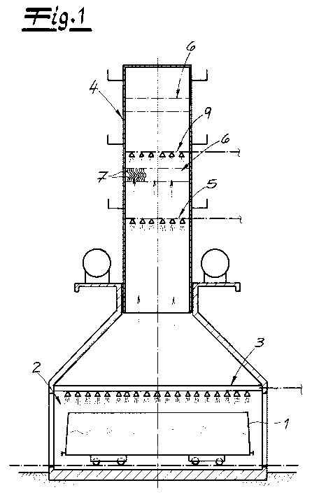
Fig. 1 shows a wet quenching tower for quenching hot coke which,
in the exemplary embodiment, is introduced into a quenching
chamber 2 by means of a quenching trolley 1. In order to cool
the hot coke and avoid burn-off, the coke received in the
quenching trolley 1 is sprayed with water by a quenching shower
unit 3, with the result that quenching vapors are formed which
contain steam and dust particles. A chimney 4, in which the
quenching vapors rise upward, is placed above the quenching
chamber 2.
Inside the chimney 4, starting from the quenching chamber 2,
above the quenching shower unit 3 a spraying device 5 is
provided, by means of which the rising quenching vapors are
additionally sprayed with quenching water. This spraying device
serves for cooling the quenching vapors further and consequently
for achieving increased condensation. In this regard, the
average drop size is also increased, and therefore separation
becomes easier in a separation device 6 which follows in the
flow direction, that is to say is arranged above. Finally,
additional dust particles from the quenching vapors are also
bound in liquid drops as a result of the additional spraying by
means of the spraying device 5. The dust particles are therefore
,
CA 02845823 2014-02-18
to some extent washed out of the quenching vapors by means of
the spraying device.
The separation device 6 is designed for vertical throughf low and
is tilted slightly with respect to the horizontal plane. The
exact orientation of the separation device 6 may be gathered
from a comparative look at fig. 1 and fig. 2, fig. 2 showing a
view rotated through 90 with respect to fig. 1.
It can already be seen from fig. 1 that the separation device 6
comprises a multiplicity of parallel lamellae 7, the lamellae 7
having in each case a branch-free cross section, and flow paths
8 being formed in each case between two adjacent lamellae 7.
According to fig. 2, in the exemplary embodiment the separation
device 6 is tilted with respect to a horizontal plane in such a
way that the individual lamellae 7 have along their longitudinal
extent a lateral gradient which may amount, for example, to
between 15 and 45 .
The shape of the lamellae 7 is illustrated by way of example in
figs. 3a and 3b. According to the invention, the direction of
the flow paths 8 formed in each case between two lamellae 7
changes more than once, according to fig. 3a the lamellae 7
having in cross section a wave shape with at least two turning
points. As a result of multiple deflection, the separation
capacity is increased in respect of drops which cannot follow
the changes in direction because of their inertia. Furthermore,
it can be gathered identically from figs. 3a and 3b that the
flow paths 8 have along their course, in the vertical direction,
CA 02845823 2014-02-18
11
an approximately uniform cross section, that is to say an
approximately uniform spacing between the lamellae 7.
Moreover, it can be seen that, according to the two exemplary
embodiments of figs. 3a and 3b, the lamellae 7 have a uniform
thickness along their cross section. The lamellae 7 illustrated
can consequently be produced especially simply by the forming of
a metal sheet or of a plastic web. Even if the lamellae are
formed by injection molding, the contour illustrated can be
produced especially simply and therefore cost-effectively.
The separation capacity in the separation device 6 depends
essentially upon the size distribution of the drops. This size
distribution can be to some extent set by the additional
spraying by means of the spraying device 5. In particular, the
shape of the lamellae 7 which is actually selected, that is to
say the exact profile of the lamellae 7 and the spacing between
the lamellae 7, can also be optimized as a function of the drop
size to be expected.
According to fig. 1, above the separation device, a scavenging
device 9 is provided, by means of which the lamellae 7 of the
separation device 6 can be cleaned. Additionally or
alternatively, a scavenging device may also be provided below
the separation device 6. On account of the simple shape of the
lamellae 7 which is illustrated in figs. 3a and 3b, these can
also be cleaned especially efficiently by means of the
scavenging device 9. In particular, complete wetting of the
lamellae 7 and therefore reliable cleaning can be achieved.
CA 02845823 2014-02-18
12
The lamellae 7 are shaped in such a way that a laminar or
essentially laminar flow is achieved as a function of the flow
velocities.
Surprisingly, efficient separation of dust particles is also
possible by means of the shape of lamellae 7 which is optimized
per se for the separation of drops. For this purpose, use may be
made of the fact that, by means of the additional spraying by
the spraying device 5, large parts of the dust are bound in
water drops, these water drops then being separated very
efficiently. In contrast to the prior art, the dust is bound in
water drops to an increased extent by the separation device 7
and is separated directly to a lesser degree.
Finally, it is indicated in fig. 1 that a further separation
device may be arranged further above, in which case this merely
indicated separation device 6 is also preferably configured as
described above.