Note: Descriptions are shown in the official language in which they were submitted.
CA 02846032 2014-03-12
COAXIAL PUMPING APPARATUS WITH INTERNAL POWER FLUID COLUMN
FIELD OF THE INVENTION
[0001] The present application relates generally to pumps, and more
particularly to
piston type pumps having increased energy efficiency, systems incorporating
such piston type
pumps, and methods of operating piston type pumps.
BACKGROUND OF THE INVENTION
[0002] It has been estimated that approximately 85% of the total cost
of operating
a conventional pump is attributable to energy consumption. Pumping systems
account for
nearly 20% of the world's electrical energy demand and range from 25% to 50%
of the energy
required by industrial plant operations.
[0003] Similarly, maintenance costs account for approximately 10% of
the total
cost of operating a conventional pump.
[0004] Pumping liquids against substantial hydraulic heads is a
problem
encountered in pumping out mines, deep wells, and similar applications such as
pumping
water back up, over a hydro dam during low energy usage periods, for
subsequent recovery
during high energy usage periods, and for run-of-the-river hydro power
applications utilizing
the potential energy of water in a standing column.
[0005] Several earlier patents attempt to provide devices which
utilize a piston
type pump where energy is recovered from a column of liquid acting downwardly
on the
piston, as the piston moves downwardly, to assist in subsequently raising the
piston with a
volume of liquid to be pumped upwardly. An example of such an earlier patent
is U.S. Patent
No. 6,193,476 to Sweeney. However such earlier devices have not been efficient
enough to
justify commercial usage. In the Sweeney patent, for example, the efficiency
of the apparatus
is significantly reduced due to the upper piston 38 having the same cross-
sectional area as
lower piston 43. Thus the pressure of liquid acting upwardly on the lower
piston 43 inhibits
downward movement of the upper piston 38 under the weight of the liquid in the
cylinder
above.
-1-
CA 02846032 2014-03-12
SUMMARY OF THE INVENTION
[00061 It is an object to the invention to provide an improved pumping
apparatus
capable of pumping liquids against significant hydraulic heads, such as
encountered in deep
wells or in pumping out mines, without requiring pumps with high output heads.
[0007] It is a further object of the invention to provide an improved
piston type
pumping apparatus with provision for energy recovery or energy conservation,
having
significantly improved efficiency compared with prior art devices.
[00081 It is still further object of the invention to provide an
improved piston type
pumping apparatus which is simple and rugged in construction, and efficient to
operate and
install.
BRIEF DESCRIPTION OF THE DRAWINGS
[0009] Features of the present disclosure will become more fully
apparent from the
following description and appended claims, taken in conjunction with the
accompanying
drawings. It will be understood these drawings depict only certain embodiments
in
accordance with the disclosure and, therefore, are not to be considered
limiting of its scope;
the disclosure will be described with additional specificity and detail
through use of the
accompanying drawings. An apparatus, system or method according to some of the
described
embodiments can have several aspects, no single one of which necessarily is
solely
responsible for the desirable attributes of the apparatus, system or method.
After considering
this discussion, and particularly after reading the section entitled "Detailed
Description of the
Preferred Embodiment" one will understand how illustrated features serve to
explain certain
principles of the present disclosure.
100101 FIG. 1 provides a cross-sectional view of a vertically oriented
pump
including a pump housing, an inlet near the bottom of the pump, and an outlet
near the top of
the pump.
[0011] FIG. 2 provides a cross-sectional view of a pump having a
tapered pump
inlet.
[00121 FIG. 3 provides a cross-sectional view of a pump wherein the
power fluid
acts on the bottom of the rod portion of the transfer piston.
-2-
CA 02846032 2014-03-12
[0013] FIG. 4A provides a cross-sectional view of a pump during the
production
stroke.
[0014] FIG. 4B provides a cross-sectional view of a pump during the
recovery
stroke.
[0015] FIG. 5A provides a cross-sectional view of a pump wherein an
oscillating
pressure is provided by a piston and cylinder system.
[0016] FIG. 5B provides a cross-sectional view of a pump wherein an
oscillating
pressure is provided by alternating the conduit valve and power release valve.
[0017] FIG. 6A provides a cross-sectional view of a pump fitted with a
filter or
screen to reduce the risk of plugging within the pump. The pump is depicted
during the power
stroke.
[0018] FIG. 6B provides a cross-sectional view of a pump according to
preferred
embodiment. The pump is depicted during the recovery stroke.
[0019] FIG. 6C provides a cross-sectional view of a pump according to a
preferred embodiment. The pump is depicted during a cleaning operation wherein
the transfer
piston is lifted beyond its highest point during normal operation.
[0020] FIG. 7A provides a cross-sectional view of a pump coaxial
disconnect in a
closed position.
[0021] FIG. 7B provides a cross-sectional view of a pump coaxial
disconnect in
an open position.
[0022] FIG. 8A provides a cross-sectional view of a subterranean switch
pump
during a power stroke.
[0023] FIG. 8B provides a cross-sectional view of a subterranean switch
pump
during a pump recovery stroke.
[0024] FIG. 9 provides a cross-section view of one embodiment of a
downhole
pump.
[0025] FIG. 9A provides a cross-section view of one embodiment of a
3.5"
downhole pump.
[0026] FIG. 9B provides a cross-section view of a connection location
for the
power fluid tube and the product fluid coaxial tube.
-3-
CA 02846032 2014-03-12
[0027] FIG. 9C provides a cross-section view of the embodiment of FIG.
9A
including the main piston seal.
[0028] FIG. 9D provides a cross-section view of the embodiment of FIG.
9A
including the seal between a power fluid chamber and a transfer chamber.
[0029] FIG. 9E provides a cross-section view of the embodiment of FIG.
9A
including the intake valve located within the bottom of the pump.
[0030] FIG. 10 provides another embodiment of a downhole pump.
[0031] FIG. 10A provides a cross-sectional view of a 1.5" stacked
downhole
pump.
[0032] FIG. 10B provides a cross-sectional view of the embodiment of
FIG. 10A
including the power fluid and product fluid coaxial tubes.
[0033] FIG. 10C provides a cross-sectional view of the embodiment of
FIG. 10A
including a main piston seal.
[0034] FIG. 10D provides a cross-sectional view of the embodiment of
FIG. 10A
including a bottom piston seal.
[0035] FIG. 11 provides another embodiment of a downhole pump.
[0036] FIG. 12 provides a figure illustrating an efficiency comparison
between a
conventional electric pump and a pump of a preferred embodiment.
[0037] FIG. 13 provides a graph illustrating efficiency of various
pumps based
upon a ratio of two areas on a piston.
[0038] FIG. 14 is a simplified elevational view, partly in section, of
a pumping
apparatus according to an embodiment of the invention;
[0039] FIG. 15 is a simplified elevational view, partly in section, of
the upper
fragment of an alternative embodiment employing a centrifugal pump;
[0040] FIG. 16 is a graph of the efficiency of the pressure head
concept of the
pump;
[0041] FIG. 17 is a sectional view of the embodiment of FIG. 14 showing
the
Force Balance in the pump;
-4-
CA 02846032 2014-03-12
[0042] FIGS. 18A and 18B are simplified sectional views showing
Pressure Head
Concept of a pump and the Power Cylinder Concept of the pump.
[0043] FIGS. 19A and 19B are simplified elevational views, partly in
section, of a
pumping apparatus in a power stroke and a recovery stroke respectively
according to another
embodiment of the invention.
[0044] FIG. 20 shows a schematic of a system wherein water at a higher
level is
directed straight to the pump to power the pump stroke.
[0045] FIG. 21 depicts an embodiment of the Hygr Fluid System wherein
the
hydraulic cylinder on the surface moves forward and produces a hydraulic
impulse transmitted
through the delivery pipe to the pump.
[0046] FIG. 22 is a photograph showing two hydraulic accumulators and
water
pumped from downhole.
[0047] FIG. 23 is a photograph showing a drive unit (forward box) and
control
unit (rear box).
[0048] FIG. 24A depicts wells in close proximity controlled by one
drive unit.
[0049] FIG. 24B depicts a drive unit for controlling wells as in FIG.
23.
[0050] FIG. 25 depicts a system utilizing an accumulator with a Hygr
Fluid
System pump.
[0051] FIG. 26 depicts a system utilizing an accumulator drive and
recycle system
with a Hygr Fluid System pump.
[0052] FIG. 27 depicts a Blair Drive system providing oil to a Hygr
Fluid System.
[0053] FIG. 28 depicts a Blair Drive system wherein gas freeflows up
the casing,
energizing the Blair Piston and oil pump.
[0054] FIG. 29 is a block diagram depicting the 4G system.
[0055] FIG. 30 is a block diagram depicting the power stroke of the 4G
system.
[0056] FIG. 31 is a block diagram depicting the recharge stroke 4G
system.
[0057] FIG. 32 depicts a system utilizing an accumulator drive with a
discharge
reset.
DETAILED DESCRIPTION OF THE PREFERRED EMBODIMENT
-5..
CA 02846032 2014-03-12
[0058] In the following detailed description, only certain exemplary
embodiments
have been shown and described, simply by way of illustration. As those skilled
in the art
would realize, the described embodiments may be modified in various different
ways, all
without departing from the spirit or scope of the present disclosure.
Accordingly, the
drawings and description are to be regarded as illustrative in nature and not
restrictive. In
addition, when an element is referred to as being "on" another element, it can
be directly on
the another element or be indirectly on the another element with one or more
intervening
elements interposed therebetween. Also, when an element is referred to as
being "connected
to" another element, it can be directly connected to the another element or be
indirectly
connected to the another element with one or more intervening elements
interposed
therebetween. Hereinafter, embodiments of the disclosure will be described
with reference to
the attached drawings. If there is no particular definition or mention, terms
that indicate
directions used to describe the disclosure are based on the state shown in the
drawings.
Further, the same reference numerals indicate the same members in the
embodiments.
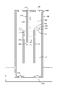
[0059] FIG. 1 illustrates an embodiment of a pumping apparatus of a
preferred
embodiment. The vertically oriented pump 100 preferably includes a pump
housing 102, at
least one inlet 104 near the bottom of the pump 100, and at least one outlet
106 near the top of
the pump 100. The pump inlet 104 includes a valve 108. The valve 108 is
preferably a one-
way valve, allowing fluid to flow through the inlet 104 into a transfer
chamber 110 inside the
pump 100, but not in the reverse direction. More preferably, the inlet valve
108 is a self-
actuating valve, such that it requires no electronic or manual control, but
rather opens and
closes solely by the force of the fluid moving therethrough and/or by pressure
changes in the
transfer chamber 110. In such embodiments, any suitable type of one-way valve
can be
utilized, including check valves and the like.
[0060] Check valves are valves that permit fluid to flow in only one
direction.
Ball check valves contain a ball that sits freely above a seat, which has only
one opening
therethrough. The ball has a diameter that is larger than the diameter of the
opening. When
the pressure behind the seat exceeds the pressure above the ball, liquid is
allowed to flow
through the valve; however, once the pressure above the ball exceeds the
pressure below the
seat, the ball returns to rest in the seat, forming a seal that prevents
backflow. The ball can
-6-
CA 02846032 2014-03-12
also be connected to a spring or other alignment device. Such alignment
devices are useful if
the pump operates in a non-vertical orientation. In some embodiments, the ball
can be
replaced by another shape, such as a cone.
[0061] Swing check valves can also be utilized. Swing check valves use
a hinged
disc that swings open with the flow. Any other suitable type of check valve,
including dual
flap check valves and lift check valves, can also be utilized. Numerous other
types of valves
can be utilized, including reed valves, diaphragm valves. The valves can
optionally be
electronically controlled. Using standard computer process control techniques,
such as those
known in the art, the opening and closing of each valve can be automated. In
such
embodiments, two-way valves can advantageously be utilized.
[0062] Any suitable number of inlets and outlets can be employed, for
example, 1,
2, 3, 4, 5, or more inlets, and 1, 2, 3, 4, 5, or more outlets. Preferably
three (3) inlets and three
(3) outlets are employed.
[0063] The pump can be of any suitable size. The preferred size can be
selected
based upon various factors such as the amount of liquid to be pumped, the type
of liquid, and
other factors. For example, the pump housing can have a diameter of 1, 3, 6,
12, 24, or 36
inches or more. In a preferred embodiment, the pump housing 102 has an outer
diameter of
about 3.5 inches. In another preferred embodiment, the pump housing 102 has an
outer
diameter of about 1.5 inches.
[0064] The pump 100 also includes a transfer piston 120, which is
reciprocatingly
mounted therein. The transfer piston 120 typically includes a piston portion
122 and a rod
portion 124. The piston portion 122 includes a channel 125 and a valve 126,
which is referred
to herein as the "transfer piston valve." Preferably, the transfer piston
valve 126 is a one-way
valve, allowing fluid to flow from the transfer chamber 110 into a product
cylinder 130, but
not in the reverse direction from the product cylinder 130 to the transfer
chamber 110.
[0065] The pump 100 also includes a vertically oriented power fluid
column 140,
which defines a power fluid tube 142. The power fluid column can be oriented
in any suitable
manner, and is not limited to a vertical orientation. For example, the power
fluid column can
be horizontal, or at any angle displaced from the vertical. In addition, the
pump 100 can
operate at any angle, including vertical, horizontal, or any angle
therebetween. The power
-7-
CA 02846032 2014-03-12
fluid tube comprises an inlet 144 such that power fluid can be provided to
and/or removed
from the power fluid tube 142.
[0066] The power fluid column 140 further includes at least one
passageway 146.
In preferred embodiments, the power fluid column includes 1, 2, 3, 4, 5, 6 or
more
passageways. This passageway 146 allows power fluid to flow freely between the
power fluid
tube 142 and a power fluid chamber 150. Preferably, the passageway 146 is
located near the
bottom of the power fluid tube 142.
[0067] In the embodiment illustrated in FIG. 1, the power fluid
chamber 150 is
defined by the exterior surface of the power fluid column 140 and the transfer
piston 120. The
power fluid chamber 150 has a top 152, also referred to herein as the "inner
surface area." In
the embodiment illustrated in FIG. 1, the inner surface area 152 is a portion
of the bottom of
the piston portion 122 of the transfer piston 120. The inner surface area 152
is the surface
area upon which the power fluid acts. The passageway 146 through which the
power fluid
enters the power fluid chamber 150 is located below the inner surface area
152.
[0068] To enclose the power fluid chamber 150, the rod portion 124 of
the transfer
piston 130 extends coaxially about the power fluid column 140. The shape of
the power fluid
column 140 and the transfer piston 120 are chosen such that they form a
slideable seal both at
the top and the bottom of the power fluid chamber 150. For example, in the
embodiment
illustrated in FIG. 1, the power fluid column 140 increases in diameter to
form a slidingly
sealable engagement with the rod portion 124 of the transfer piston 120 at the
bottom of the
power fluid chamber 150, thereby ensuring a secure power fluid chamber 150.
The spacing
between components, such as between the power fluid column 140 and the rod
portion 124, is
typically determined by the seal utilized. The type of seal utilized is
determined by the
operating conditions (i.e. pressure and temperature) and the fluids utilized.
In a preferred
embodiment, a standard o-ring seal is utilized. In high temperature
applications, a ring such
as those used in automobile pistons can be utilized.
[0069] FIG. 1 is a simplified drawing of a pump of one preferred
embodiment.
Seals and other conventional elements are omitted from the drawing for
purposes of
illustration. Numerous modifications can be made to the embodiment illustrated
in FIG. 1.
-8-
CA 02846032 2014-03-12
As just one example, the piston portion 122 of the transfer piston 120 can
alternatively be
located at the bottom of the rod portion 124, rather than adjacent the top as
illustrated in FIG.
1. In addition, the rod 124 and piston portions 122 can vary in shape and
thickness. For
example, the thickness of the piston portion 122 can be selected based on the
pressure applied.
[0070] The operation of the pump illustrated in FIG. 1 is described in
connection
with pumping of oil from an oil well. However, the pumps of preferred
embodiments are also
suitable for pumping other liquids as well (e.g., ground water, subterranean
liquids, brackish
water, sea water, waste water, cooling water, gas, coolants, and the like).
[0071] The operating cycle of the pump 100 can be divided into two
separate
stages, referred to as the "production stroke" or "power stroke" and the
"recovery stroke."
During the production stroke, water is supplied under pressure through the
power fluid inlet
144. This forces water down the power fluid tube 142, through the passageway
146, and into
the power fluid chamber 150. The water acts on the inner surface area 152 to
lift the transfer
piston 120. As the transfer piston 120 lifts against the weight of the oil in
the product cylinder
130, the transfer piston valve 126 closes. As the transfer piston 120 is
lifted, the oil in the
product cylinder 130 is forced out through the pump outlet 106. This oil can
then be
recovered by suitable means or apparatus, such as known in the art. For
example, the outlet
106 can be connected to a pipe, which directs the oil to a desired location.
Sometimes, the oil
can be delivered to the wellhead, where the oil can be directed to separation
and/or storage
facilities. Storage facilities, when employed, can be either above ground or
below ground.
Where crude oil is recovered, the oil can be transferred to a refinery or
refineries by pipeline,
ship, barge, truck, or railroad. Where natural gas is recovered, the gas is
typically transported
to processing facilities by pipeline. Gas processing facilities are typically
located nearby so
impurities such as sulfur can be removed when possible. In cold climate
applications, the oil
can be transferred via heated lines.
[0072] As the transfer piston 120 is rising with the transfer piston
valve 126 closed
as described above, a vacuum, partial vacuum, or low pressure volume is
created in the
transfer chamber 110. The decrease in pressure in the transfer chamber 110
causes the inlet
-9-
CA 02846032 2014-03-12
valve 108 to open and oil from the well is drawn into the transfer chamber 110
through the
pump inlet 104.
[0073] The transfer piston 120 rises until the top of the transfer
piston 120 contacts
the top of the pump or, alternatively, until the force generated by the power
fluid and acting on
the inner surface area 152 equals the force generated by the weight of the oil
in the product
cylinder 130 plus the weight of the transfer piston 120. As the transfer
piston 120 reaches the
highest point (similar to top dead center for a piston in an engine), the
product cylinder 130 is
at its smallest volume and the transfer chamber 110 is at its largest volume.
The inlet valve
108 is open, but the transfer piston valve 126 is closed.
[0074] As the transfer piston 120 reaches its highest point, the
pressure of the
power fluid is reduced until the downward force, provided by gravity acting on
the weight of
the oil in the product cylinder 130, the weight of the oil in the product
pipeline above the
pump, and the weight of the transfer piston, is greater than the upward force
provided by the
power fluid acting on the inner surface area. This causes the transfer piston
120 to fall, and
initiates the recovery stroke. In some embodiments, the pressure of the power
fluid can be
reduced such that the power fluid chamber serves as a vacuum or partial
vacuum, providing an
additional force to lower the transfer piston 120. In some embodiments, the
fluid in the
product cylinder can be pumped to a higher elevation or into a pressure vessel
to supply
additional energy for the recovery stroke.
[0075] As the transfer piston 120 lowers, the pressure inside the
transfer chamber
110 increases. The increase in pressure causes the inlet valve 108 to close,
thereby sealing the
pump inlet 104. Alternatively, sensors can be employed and the valves
controlled
electronically. As the pressure inside the transfer chamber 110 continues to
increase due to
the lowering transfer piston 120, the transfer piston valve 126 opens, thereby
allowing oil
located within the transfer chamber 110 to flow into the product cylinder 130.
The transfer
piston 120 continues to lower until the rod portion 124 of the transfer piston
120 contacts the
bottom of the pump 100, or alternatively until the force generated by the
power fluid equals
the force generated by the weight of the oil and the weight of the transfer
piston. Thereafter,
-10-
CA 02846032 2014-03-12
power fluid is introduced under pressure, acting on the inner surface area 152
and initiating
the production stroke.
[0076] The operation of the pump is maintained by providing an
oscillating or
periodic pressure to the power fluid. The power fluid can be any suitable
fluid. In one
embodiment, the power fluid is water; however, numerous other power fluids can
be utilized,
including but not limited to sea water, waste water from oil recovery
processes, and product
fluid (i.e. oil if the pump is being used in oil recovery processes). In other
embodiments, the
power fluid can be gas or steam. Thus, the term "fluid," as used herein, is
not restricted to
liquids, but is intended to have a broad meaning, including gases and vapors.
In one
embodiment, the power fluid is air. In another embodiment, the power fluid is
steam.
[0077] The appropriate power fluid for a particular application can be
based on a
variety of factors, including cost and availability, corrosiveness, viscosity,
density, and
operating conditions. For example, the power fluid can be the same fluid as
the product fluid.
This allows the product fluid and the power fluid to have the same density,
thereby
simplifying the forces acting on the transfer piston. Alternatively, a more
dense power fluid
can be utilized. Utilizing a power fluid that is more dense than the product
fluid allows the
pump to operate with either (a) the power fluid supplied at a lower pressure,
or (b) a smaller
inner surface area. For example, in some embodiments, brine or mercury can be
utilized.
Preferably, a low-viscosity power fluid is utilized, as use of a high
viscosity power fluid may
cause pressure loss due to friction between the power fluid and the power
fluid column.
[0078] In some embodiments, such as where the pump is utilized in high
temperature applications, a power fluid such as motor oil can be utilized.
Similarly, various
oils and liquids with low freezing points can be utilized in cold
environments.
[0079] The pump can be operated by one power source, or a number of
pumps can
be operated by the same power source. For example, in some applications such
as
construction, mine dewatering, or other commercial and industrial
applications, several pumps
can be operated by the same power source. In addition, several pumps can be
operated using
an air system, such as in a manufacturing facility.
[0080] The pump 100 and its components can be any suitable shape. The
use of
the terms column, chamber, tube, rod, and the like are not intended to limit
the shape of the
-1 1-
CA 02846032 2014-03-12
components. Rather, these terms are used solely to aid in describing
particular embodiments.
For example, with reference to FIG. 1, the pump housing 102 and power fluid
column 140
can both be substantially cylindrical in shape. Thus, the piston portion 122
of the transfer
piston 120 seals the annular gap between these two cylinders. However, the
pumps of
preferred embodiments are not limited to this configuration; the pump housing
102 can be any
shape, and the power fluid column 140 can be any shape. For example, besides
being formed
in a circular shape, the pump components can also be square, rectangular,
triangular, or
elliptical.
[0081] The pump housing 102 and the pump components, such as the power
fluid
column 140 and the transfer piston 120, can be constructed of any suitable
material. For
example, in preferred embodiments, these components can be constructed of 304
or 316
stainless steel. In some embodiments, such as when the pump is in contact with
highly
corrosive materials, a 400 series stainless steel can be used. One of skill in
the art will
appreciate that selection of the pump materials depends on a variety of
factors, including
strength, corrosion resistance, and cost. In high temperature applications,
pump components
can preferably be constructed of ceramic, carbon fiber, or other heat
resistant materials.
[0082] Referring still to FIG. 1, the upper surface of the transfer
piston 120
defines an area A.1. This upper surface can be planar, but can also be
concave, convex, or
linearly sloping. The surface area A1 supports the weight of the fluid in the
product cylinder
130 and any standing column of fluid above the pump. That is, the fluid in the
product
cylinder 130 and in any vertical pump outlet pipes creates a downward force on
the transfer
piston 120. This downward force is equal to the mass of the product fluid
multiplied by
gravity, or alternatively, it is equal to the pressure of the product fluid in
the product cylinder
130 multiplied by the surface area Ai. Gravity acting on the weight of the
transfer piston 120
also creates a downwards force.
[0083] The bottom surface of the transfer piston 120 exposed to the
fluid in the
transfer chamber 110 also defines an area, A2. A2 is the surface area upon
which the fluid in
the transfer chamber acts. During the recovery stroke, the fluid in the
transfer chamber 110
exerts an upwards force on the transfer piston equal to the pressure inside
the transfer chamber
-12-
CA 02846032 2014-03-12
110 multiplied by the surface area A2 upon which it acts. For the embodiment
illustrated in
FIG. 1, the difference between A1 and A2 represents the inner surface area,
A3, the area upon
which the pressure fluid acts.
[0084] Therefore, if:
P1 = Pressure of product fluid in the product chamber 130
A1 = Area upon which fluid in the product chamber 130 acts
P2= Pressure offluid in the transfer chamber 110
A2= Area upon which fluid in the transfer chamber 110 acts
Ppf = Pressure ofpower fluid in the power fluid chamber 150
A3= (Ai¨ A2) = Pressure upon which power fluid acts ("inner surface area')
T = Weight of the transfer piston
[0085] And ignoring any forces caused due to friction between the
components
and seals inside the pump, then:
Force down= P T
Force up = P2A2 P13f143
[0086] Accordingly, changes to the values for A1 and A2 influence the
amount of
pressure required for the power fluid to lift the piston during the power
stroke. The work
required to lift the piston is determined by multiplying the force exerted by
the power fluid by
the distance the piston travels. Therefore, if S represents the distance the
piston travels from
its lowest position to its highest position, then the work (Win) necessary to
lift the piston is:
Wm = PpfA 38
[0087] Accordingly, the amount of work required is also impacted by
the ratio of
AI:A3, as is the pump's efficiency. In a preferred embodiment, the ratio of Ai
:A3 is from
about 1.25 to about 4.
[0088] FIG. 2 illustrates another embodiment of a pump. The pump is,
in many
respects, similar to the embodiment described above in connection with FIG. 1.
As shown in
FIG. 2, the pump inlet 204 is not located on the bottom of the pump 100, as
illustrated in
FIG. 1. The inlet 204 can be located at any point below the transfer piston
valve 226. In a
preferred embodiment, the inlet 204 is not located on the bottom of the pump
housing 202,
because when the pump is placed down a well, the bottom of the pump can rest
on the ground
-13-
CA 02846032 2014-03-12
beneath the fluid being pumped. Pump inlets on the bottom of the pump often
become
plugged. As illustrated in FIG. 2, the pump inlet 204 can be tapered such that
the narrowest
portion of the inlet is at the exterior of the pump housing 202. In a
preferred embodiment, the
inlet has a one-eighth inch external opening, and has an inwardly enlarging
taper. This
tapering of the inlet 204 prevents suspended particles from becoming lodged
within the pump.
[0089] The embodiment illustrated in FIG. 2 provides one example of a
one-way
valve system that can be utilized. The inlet 204 comprises a hole or
passageway, as
illustrated. A conical check valve member 208 is located near the bottom of
the power fluid
column 240. As the pressure inside the transfer chamber 210 decreases, the
check valve
opens, allowing fluid to flow through the inlet 204 into the transfer chamber
210. The conical
valve member 208 can rise up freely, or it can rise until it reaches a stop
209, as illustrated in
FIG. 2. The valve member 208 can also be slideably coupled to the power fluid
column 240.
[0090] As illustrated, the pump 200 is in the recovery stroke. The
increased
pressure inside the transfer chamber 210 has caused the inlet valve member 208
to lower. As
illustrated, the valve member 208 has lowered and formed a sealing engagement
with the
interior surface of the pump housing 202 (often referred to as the valve
"seat"), thereby
preventing fluid from flowing out of the transfer chamber 210 through the
inlet holes 204.
[0091] The embodiment illustrated in FIG. 2 also utilizes a conical
check valve as
the transfer piston valve 226. Any suitable type of one-way valve can be used,
and any
combination of valve types can be used for the pump inlet valve 208 and the
transfer piston
valve 226. As previously described, automated valves and two-way valves can
also be
utilized with appropriate controls. As described previously in connection with
pump inlet
valve 208, the conical portion of the transfer piston valve 226 can be
slideably coupled to the
power fluid column 240. The amount of travel the conical portion of the piston
valve 226 has
can be limited by a stop (not shown). In a preferred embodiment, the valves
208, 226 are
spring loaded. In other embodiments, the valves can be guided by other
mechanisms, or,
alternatively, free of constraints.
[0092] In the embodiment illustrated in FIG. 2, the transfer piston
220 comprises a
channel 225. The transfer piston channel 225 can also be tapered to prevent
solid particles
- 1 4-
CA 02846032 2014-03-12
from being lodged therein. Any number of piston channels and valves can be
utilized. For
example, the transfer piston can include 1, 2, 3, 4, 5, or 6 or more channels
and/or valves.
[0093] As illustrated, the pumping apparatus 200 is in the recovery
stroke. The
pressure inside the transfer chamber 210 is greater than the pressure inside
the product
cylinder 230, and the transfer piston valve 226 is open, allowing fluid to
flow from the
transfer chamber 210 into the product cylinder 230.
[0094] The embodiment illustrated in FIG. 2 employs a preferred method
for
sealing the transfer piston 220. Sealing mechanisms 228 are used to prevent
fluid
communication between the transfer chamber 210 and the product cylinder 230,
and between
the transfer piston 220 and the power fluid column 240 to ensure a secure
power fluid
chamber 250. Methods of creating and maintaining a seal are well known in the
art, and any
such suitable method of forming a seal can be utilized with the pumps provided
herein. For
example, rings formed of polyurethane or polytetrafluoroethylene (PTFE) can be
used.
[0095] The embodiment illustrated in FIG. 2 further utilizes a top cap
260. The
top cap 260 serves as a mechanism 264 for connecting the source of the power
fluid to the
power fluid tube 242. Any suitable connection mechanism, including those
connection
mechanisms as known in the art, can be employed. The top cap 260 also provides
a
mechanism 262 for connecting the pump outlet 206 to a recovery unit (not
shown). For
example, the top cap 260 can include threads to which a pump can be connected,
or a seat to
which a flanged pipe can be connected.
[0096] FIG. 3 illustrates another embodiment of a pumping apparatus.
The
embodiment illustrated in FIG. 3 is similar in many respects to the
embodiments illustrated in
FIG. 1 and FIG. 2. However, the embodiment in FIG. 3 utilizes the bottom of
the rod
portion 324 of the transfer piston 320 as the inner surface area 352 upon
which the power
fluid acts. Accordingly, the power fluid chamber 350 is enclosed not only by
the rod portion
324 of the transfer piston 320 and the power fluid column 340, but also by a
third component,
referred to herein as the power fluid containment portion 356. This
containment portion 356,
which provides an outer wall for the power fluid chamber 350, can be formed by
increasing
the thickness of the pump housing 302 below the inlet 304, as illustrated in
FIG. 3. However,
-15-
CA 02846032 2014-03-12
numerous other configurations and/or mechanisms can alternatively enclose the
power fluid
chamber. As an example, if the pump 300 has a 3 inch diameter, and the power
fluid column
340 and power fluid chamber 350 have a combined diameter of 1.5 inches, then
the pump
housing 302 below the inlet 304 can be 1.5 inches thick. However, if the
embodiment
illustrated in FIG. 1 is utilized, and the transfer chamber occupies an
additional 1 inch of the
diameter, then the pump housing 302 can be only 0.5 inches thick.
[0097] The transfer piston 320, which is reciprocatingly mounted about
the power
fluid column 340, forms a slideable and sealing engagement with both the power
fluid column
340 and the power fluid containment portion 356. The pump inlet 304, as
illustrated in the
embodiment in FIG. 3, is located above the power fluid containment portion 356
and the
upper surface of the power fluid containment portion 356 serves as the base
for the transfer
chamber 310. However, the inlet 304 can alternatively extend through the power
fluid
containment portion 356.
[0098] FIG. 4A and Fig. 4B illustrate another embodiment of the
pumping
apparatus. In many ways, the embodiment illustrated in FIG. 4A and Fig. 4B is
similar to the
embodiment discussed above in connection with FIG. 3. FIG. 4A and Fig. 4B
illustrate using
conical check valves for both the inlet valve 408 and the transfer piston
valve 426.
[0099] The embodiments illustrated in FIG. 3, FIG. 4A, and FIG. 4B
operate in
manner similar to those illustrated in FIG. 1 and FIG. 2. The operation of the
pumps of
embodiments illustrated in FIG. 4A and FIG. 4B is as follows. Pump dimensions
and
characteristics described herein are provided to aid in the description only,
and are not meant
to limit the scope of the application.
[0100] FIG. 4A represents one embodiment of a pump during the
production
stroke. The pump 400 can have any outer diameter, including 1, 1.5, 2, 3, 4,
6, 12, or 24
inches or more. The pump 400 can be any height. In a preferred embodiment, the
outer
diameter of the pump housing 402 is about 1.5 inches, and the power fluid
column 440 is
about 0.5 inches in diameter. The pump 400, measured from the bottom of the
pump to the
top of the top cap 460, is about 19 inches in height. The center of the inlet
hole 404 is about 8
inches from the bottom of the pump. When the transfer piston 420 is at its
lowest position,
-16-
CA 02846032 2014-03-12
the height of the transfer chamber 410 is about 0.7 inches. The pump is placed
in a well at a
depth of about 1000 feet and both the product fluid and the power fluid are
water.
[0101] The fluid in the product cylinder 430, and the standing column
of water
above the pump, exerts a pressure Pi on the transfer piston 420. The downward
force acting
on the transfer piston 420 is equal to this pressure multiplied by the surface
area of the piston
upon which it acts, Al. Gravity acting on the weight of the transfer piston
420 also creates a
downwards force; however, because the piston of this embodiment is only about
1 to about 2
pounds, its effect may be negligible. The resistance R caused by the friction
of the seals also
exerts a downward force as the piston 420 is raised.
[0102] The force lifting the transfer piston 420 is equal to the power
fluid pressure,
Ppf, multiplied by the surface area upon which it acts, A3. To lift the
transfer piston, the force
supplied by the power fluid must be greater than the downward force previously
discussed.
Therefore, the net force on the piston is given by:
Fõt = Fup¨ Fdown = Ppf43 ¨ P .1241 ¨ R
[0103] Although the resistance of the seals can be considered it is
ignored here to
describe this embodiment. In some embodiments, the ratio of A1 to A3 is
between about 1.25
and about 4. In a preferred embodiment, the ratio of A1:A3 is about 2:1.
Therefore,
Fnet = PpiA3¨ P12A3
[0104] In order for this net force to be positive, the pressure of the
power fluid Ppf
must be at least twice as great as the pressure of the standing column, 1) I.
Since the pump is
placed at a depth of about 1000 ft, P1 is approximately 445 psi (pounds per
square inch). The
power fluid is supplied at least double this pressure, or 890 psi. Because the
force exerted by
the power fluid is proportional to its density, it can be seen that if a power
fluid is utilized that
is twice as dense as the water being pumped, the power fluid only needs to be
supplied at 445
psi to raise the piston.
[0105] When power fluid is supplied at this pressure, the power fluid
acts against
the inner surface area 452, thereby causing the transfer piston 420 to rise.
As the transfer
piston 420 lifts against the weight of the fluid in the product chamber 430,
the transfer piston
valve 426 closes, thereby sealing the transfer piston channel 425. As the
transfer piston 420
-17-
CA 02846032 2014-03-12
rises, the fluid in the product chamber 430 is forced out of the pump through
the pump outlet
406.
[0106] As the transfer piston 420 rises with the transfer piston valve
426 closed,
the pressure in the transfer chamber 410 decreases. The pressure drop inside
the transfer
chamber 410 causes the inlet valve 408 to open, thereby allowing fluid from
the source to be
drawn through the pump inlet 404 into the transfer chamber 410. As described
previously, the
inlet holes can be tapered to prevent debris from becoming lodged therein. As
illustrated, the
inlet valve 408 can be guided by, or alternatively slideably coupled to, the
rod portion 424 of
the transfer piston 420. The transfer piston 420 rises until the top of the
transfer piston 420
reaches a predetermined stopping point, such as when the transfer piston hits
the top cap 460,
or alternatively until the force generated by the power fluid equals the force
generated by the
weight of the product fluid and the weight of the transfer piston 420. For the
embodiment
described above, the top of the piston stroke can be set by decreasing the
pressure of the
power fluid below 890 psi. When the transfer piston is at the top of its
stroke, the transfer
chamber is about 6.7 inches in height, resulting in a stroke length of about 6
inches.
[0107] Once the transfer piston 420 reaches its highest point, the
recovery stroke
begins. As illustrated in FIG. 4B, during the recovery stroke the pressure of
the power fluid is
reduced until the weight of the fluid in the product chamber 430 plus the
weight of the transfer
piston 420 is greater than the force provided by the power fluid and the fluid
in the transfer
chamber 410. This causes the transfer piston 420 to fall, thereby increasing
the pressure of the
trapped fluid in the transfer chamber 410. The increased pressure inside the
transfer chamber
410 causes the inlet valve 408 to close and seal the pump inlet 404. As the
pressure continues
to increase inside the transfer chamber 410, it causes the transfer piston
valve 426 to open,
and fluid is forced from the transfer chamber 410 to the product chamber 430
via the transfer
piston channel 425. Like the pump inlet holes, the transfer piston channel 425
can be tapered
to prevent debris from becoming lodged therein. In some embodiments, the
transfer piston
channel 425 had a diameter that is larger than the diameter of the pump inlet
holes, thereby
allowing any particles that enter the inlet 404 to pass through the pump 400.
The transfer
piston 420 continues to fall until the bottom of the rod portion 424 of the
transfer piston 420
-1 8-
CA 02846032 2014-03-12
contacts the bottom of the pumping apparatus, or alternatively until the
upwards force
generated by the power fluid and the fluid in the transfer chamber 410 equals
the downwards
force generated by both the weight of the fluid in the product chamber 430 and
the weight of
the transfer piston 420.
[0108] The speed at which the pump operates can be varied as desired.
The time
required for one "stroke," which is defined as the transfer piston 420 moving
from its lowest
position, through its highest position and returning to its lowest position,
can be set by the
operator. For the embodiment described above, wherein the outer diameter of
the pump is
about 1.5 inches, a preferred speed is about 6 strokes per minute, which
provides a displaced
volume of about three barrels per day. However, any range of speeds can be
utilized
depending upon the application. For example, in some embodiments, only one
stroke per
minute can be preferable. In other applications, speeds of 20 strokes per
minute or more can
be preferable. The volume of product fluid pumped is determined by the speed
of the pump
and the length of the stroke. Any suitable stroke length can be utilized,
including 6, 12, 24, or
36 inches or more.
[0109] The operating cycle of the pump 400 is maintained by providing
an
oscillating pressure to the power fluid. This oscillating pressure can be
provided by any
suitable method, including a number of methods known in the art. Among such
methods are
those described below and those disclosed in United States Patent Publication
No. 2005-
0169776-A1, the contents of which are incorporated herein by reference in its
entirety.
[0110] For example, as illustrated in FIG. 5A, the oscillating
pressure can be
provided by a piston and cylinder system, wherein the piston is moved by a
motor or engine
with a crank mechanism, or a pneumatic or hydraulic device. These systems can
be controlled
manually, by an electronic timer, by a programmable logic controller ("PLC"),
by computer,
or by a pendulum. As illustrated in FIG. 5A, a conduit 546 delivers power
fluid to the power
fluid inlet 544 from a power fluid source 570. The power fluid source 570
comprises a
cylinder 572 and a power fluid piston 574. During the power stroke, the power
fluid piston
574 moves to the left, forcing power fluid from the power fluid cylinder 572,
through the
conduit 546, to the power fluid inlet 544. This increases the power fluid
pressure inside the
power fluid chamber 550, thereby lifting the transfer piston 520. During the
recovery stroke,
-19-
CA 02846032 2014-03-12
the power fluid piston 574 moves to the right. Power fluid is forced out of
the power fluid
chamber 550, and the transfer piston 520 lowers.
[0111] In some applications, the power fluid in the conduit 546 alone
can provide
substantial pressure to the power fluid chamber 550. As illustrated in FIG.
5B, the power
source can be a fluid source stored at an elevation that is higher than that
where the product
fluid is recovered 507. The difference in elevation 578 provides a natural
source of pressure.
During the power stroke, a valve 576 in the conduit is opened, allowing power
fluid to flow
from the power fluid source 570, through the conduit 546, and into the power
fluid chamber
550. The difference in elevation 578 alone can cause the transfer piston 520
to rise and pump
fluid out of the pump outlet 506 at the recovery elevation 507.
[0112] During the recovery stroke, the conduit valve 576, which is
located at an
elevation that is lower than the recovery elevation 507, is closed and a power
fluid release
valve 577 is opened. The power fluid release valve 577 is at an elevation that
is lower than
the elevation of the conduit valve 576. The power fluid release valve 577 is
at an elevation
lower than the product fluid recovery elevation 507, and the pressure in the
pump outlet line
forces the transfer piston 520 down and power fluid drains from the power
fluid release valve
577.
[0113] Accordingly, in the embodiment illustrated in FIG. 5B, the
oscillating
pressure is provided by alternating the conduit valve 576 and power fluid
release valve 577.
The differences in elevation can be selected depending on the relative
densities of the power
fluid and the product fluid.
[0114] In some embodiments, the pumping apparatus comprises a power
fluid
column internal to the product fluid. Such a design is advantageous because
the power fluid
can be supplied at a greater pressure without compromising the structural
integrity of the
column containing the power fluid. For example, if a pump is 3 inches in
diameter, and if the
power fluid column is external to the product fluid column, then the diameter
of the power
fluid column is 3 inches. Since the force (F) exerted by the power fluid on
the wall of the
power fluid column is determined by multiplying the pressure (P) of the power
fluid by the
surface area of the column, and the surface area of a cylinder is determined
by multiplying the
-20-
CA 02846032 2014-03-12
cylinder's circumference by its height, then the force on an externally placed
power fluid
column is:
Fextemal = n(diameter)(Pressure)(height) = 3137r(height)
[0115] Assuming the same 3 inch diameter pump uses a 1 inch diameter
internal
power fluid column, the force on the power fluid column is:
Fintemal = n(diameter)(pressure)(height) = 1Px(height)
[0116] Assuming the height of the column is the same for each pump,
the
internally placed power fluid column exerts only one third of the force on the
pump material
when compared to the externally placed power fluid column. For a pump
constructed with a
material capable of sustaining a maximum force, the power fluid can be
supplied at 3 times
the pressure if the power fluid column is internal rather than external.
[0117] Similarly, the hoop stress for a thin walled cylinder is equal
to the pressure
inside the cylinder multiplied by the radius of the cylinder, divided by the
wall thickness.
Accordingly, as the radius increases, the hoop stress increases linearly. In
applications that
require the power fluid to be supplied at significant pressures, such as when
pumping fluid
from very deep wells, it is preferable to have an internal power fluid column.
For example,
for a water well at a depth of 10,000 feet, the power fluid can be supplied at
a pressure of
about 10,000 psi.
[0118] Below, Tables 1 through 20 include data compiled from the pumps
of the
present disclosure. In reference to the pipes of FIG. 5A and FIG. 5B, the data
shows that the
greater the diameter the conduit 546 the greater the (volume) required in the
cylinder 572.
The greater cylinder volume is required to compensate for the greater amount
of fluid
compression loss in the conduit 546. This fluid compression loss is linearly
proportional to
the volume of the fluid in the conduit 546 for any given drive pressure. Table
1 gives the bulk
modulus value of typical hydraulic water-based fluids and volume of fluid
within different
conduit pipes for depths up to 4000 feet. Tables 2 through 10 illustrate the
volumes of
compression fluid losses for typical hydraulic water-based fluids for given
conduits (546) at
different depths. Table 2 illustrates the volume of fluid losses for a drive
pressure of 500 psi.
Table 3 illustrates the volume of fluid losses for a drive pressure of 750
psi, etc. These
volumes of water-based hydraulic fluid losses must be compensated by a
corresponding
-21-
CA 02846032 2014-03-12
increase in volume of the drive cylinder (572). Table 11 gives the bulk
modulus value of
typical hydraulic oil-based fluids and volume of fluid within different
conduit pipes for depths
up to 4000 feet. Tables 12 through 20 illustrate the volumes of compression
fluid losses for
typical hydraulic oil-based fluids for given conduits (546) at different
depths. Table 12
illustrates the volume of fluid losses for a drive pressure of 500 psi. Table
13 illustrates the
volume of fluid losses for a drive pressure of 750 psi, etc. These volumes of
oil-based
hydraulic fluid losses must be compensated by a corresponding increase in
volume of the
drive cylinder (572).
-22-
CA 02846032 2014-03-12
TABLE 1
DATA for water
Bulk Modulus = (psi) 300000
VOL. @ VOL. @ VOL. @ VOL. @ VOL. @
PIPE OD ID
WALL DEPTH DEPTH DEPTH DEPTH DEPTH
SIZE/SCHEDULE OD AREA ID AREA THCK 500 750 1000 1250
1500
(in) (inA2) (in) (inA2) (in) (inA3) (103)
(inA3) _ (inA3) (inA3)
1/8" SCH 40 0.405 0.129 0.269 0.057 0.068 340.8 511.2
681.6 852,1 1022.5
1/4" SCH 40 0.540 0.229 0.364 0.104 0.088 624.1 936.1
1248,1 1560.1 1872.2
3/8" SCH 40 0.675 0.358 0.493 0.191 0.091 1144.8
1717.1 2289.5 2861.9 3434.3
1/2" SCH 40 0.840 0.554 0.622 0.304 0.109
1822.2 2733.3 3644.4 4555.6 5466.7
3/4" SCH 40 1.050 0.865 0.824 0.533 0.113
3198.0 4797.0 6396.0 7994.9 9593.9
1" SCH 40 1.315 1.357 1.049 0.864 0.133
5182.9 7774.3 10365.8 12957.2 15548.7
1 1/4" SCH 40 1.660 2.163 1.380 1.495 0.140 8969.7 13454.6 17939.4
22424.3 26909.2
1 1/2" SCH 40 1.900 2.834 1.610 2.035 0.145 12208.8 18313.2 24417.6 30522.0
36626.4
1/8" SCH 80 0.405 0.129 0.215 0.036 0.095 217.7 326.6
435.4 544.3 653.2
1/4" SCH 80 0.540 0.229 0.302 0.072 0.119 429.6 644.4
859.1 1073.9 1288.7
3/8" SCH 80 0.675 0.358 0.423 0.140 0.126 842.8
1264.1 1685.5 2106.9 2528.3
1/2" SCH 80 0.840 0.554 0.546 0.234 0.147
1404.1 2106.2 2808.3 3510.3 4212.4
3/4" SCH 80 1.050 0.865 0.742 0.432 0.154
2593.2 3889.7 5186.3 6482.9 7779.5
1" SCH 80 1.315 1.357 0.957 0.719 0.179 4313.6
6470.5 8627.3 10784.1 12940.9
1 1/4" SCH 80 1.660 2.163 1.278 1.282 0.191 7692.8 11539.2 15385.5
19231.9 23078.3
1 1/2" SCH 80 1.900 2.834 1.500 1.766 0.200 10597.5 15896.3 21195.0 26493.8
31792.5
1/2" SCH 160 0.840 0.554 0.464 0.169 0.188 1014.0 1521.1
2028.1 2535.1 3042.1
3/4" SCH 160 1.050 0.865 0.612 0.294 0.219 1764.1 2646.2
3528.2 4410.3 5292.3
1" SCH 160 1.315 1.357 0.815 0.521 0.250 3128.5 4692.7 6257.0 7821.2
9385.5
1 1/4" SCH 160 1.660 2.163 1.160 1.056 0.250
6337.8 9506.7 12675.6 15844.4 19013.3
1 1/2" SCH 160 1.900 2.834 1.338 1.405 0.281 8432.0
12648.1 16864.1 21080.1 25296.1
-23-
CA 02846032 2014-03-12
TABLE 1
(cont' d)
DATA for water
Bulk Modulus = (psi) 300000
VOL. @ VOL. @ VOL. @ VOL. @ VOL. @
PIPE OD ID
WALL DEPTH DEPTH DEPTH DEPTH DEPTH
SIZE/SCHEDULE OD AREA ID AREA THCK 1750 2000 2250 2500 2750
(in) (inA2) (in) (inA2) (in) (inA3) (inA3)
(inA3) (inA3) (inA3)
1/8" SCH 40 0.405 0.129 0.269 0.057 0.068 1192.9 1363.3 1533.7
1704.1 1874.5
1/4" SCH 40 0.540 0.229 0.364 0.104 0.088 2184.2 2496.2 2808.3
3120.3 3432.3
3/8" SCH 40 0.675 0.358 0.493 0.191 0.091 4006.7 4579.0 5151.4
5723.8 6296.2
1/2" SCH 40 0.840 0.554 0.622 0.304 0.109 6377.8 7288.9 8200.0
9111.1 10022.2
3/4" SCH 40
1.050 0.865 0.824 0.533 0.113 11192.9 12791.9 14390.9 15989.9 17588.9
1" SCH 40
1.315 1.357 1.049 0.864 0.133 18140.1 20731.6 23323.0 25914.4 28505.9
1 1/4" SCH 40
1.660 2.163 1.380 1.495 0.140 31394.0 35878.9 40363.8 44848.6 49333.5
1 1/2" SCH 40
1.900 2.834 1.610 2.035 0.145 42730.8 48835.2 54939.6 61044.0 67148.4
1/8" SCH 80 0.405 0.129 0.215 0.036 0.095 762.0 870.9 979.7
1088.6 1197.5
1/4" SOH 80 0.540 0.229 0.302 0.072 0.119 1503.5 1718.3 1933.1
2147.9 2362.6
3/8" SCH 80 0.675 0.358 0.423 0.140 0.126 2949.6 3371.0 3792.4
4213.8 4635.2
1/2" SCH 80 0.840 0.554 0.546 0.234 0.147 4914.4 5616.5 6318.6
7020.6 77221
3/4" SCH 80
1.050 0.865 0.742 0.432 0.154 9076.0 10372.6 11669.2 12965.8 14262.4
1" SCH 80
1.315 1.357 0.957 0.719 0.179 15097.8 17254.6 19411.4 21568.2 23725.1
1 1/4" SCH 80
1.660 2.163 1.278 1.282 0.191 26924.7 30771.1 34617.5 38463.8 42310.2
1 1/2" SCH 80
1.900 2.834 1.500 1.766 0.200 37091.3 42390.0 47688.8 52987.5 58286.3
1/2" SCH 160 0.840 0.554 0.464 0.169 0.188 3549.2 4056.2 4563.2
5070.2 5577.2
3/4" SCH 160 1.050 0.865 0.612 0.294 0.219 6174.4 7056.4 7938.5
8820.5 9702.6
1" SCH 160 1.315 1.357 0.815 0.521
0.250 10949.7 12514.0 14078.2 15642.5 17206.7
1 1/4" SCH 160
1.660 2.163 1.160 1.056 0.250 22182.2 25351.1 28520.0 31688.9 34857.8
1 1/2" SCH 160
1.900 2.834 1.338 1.405 0.281 29512.2 33728.2 37944.2 42160.2 46376.3
-24-
CA 02846032 2014-03-12
TABLE 1
(cont' d)
DATA for water
Bulk Modulus = (psi) 300000
VOL. @ VOL. @ VOL. @ VOL. @ VOL. @
PIPE OD ID
WALL DEPTH DEPTH DEPTH DEPTH DEPTH
SIZE / SCHEDULE OD AREA ID AREA THCK 3000 3250 3500 3750 4000
(in) (inA2) (in) (inA2) (in) , (inA3)
(inA3) (inA3) (inA3) (inA3) _
1/8" SCH 40 0.405 0.129 0.269 0.057 0.068
2044.9 2215.3 2385.7 2556.2 2726.6
1/4" SCH 40 0.540 0.229 0.364 0.104 0.088
3744.3 4056.4 4368.4 4680.4 4992.4
3/8" SCH 40 0.675 0.358 0.493 0.191 0.091 6868.6
7440.9 8013.3 8585.7 9158.1
1/2" SCH 40
0.840 0.554 0.622 0.304 0.109 10933.3 11844.5 12755.6 13666.7 14577.8
3/4" SCH 40
1.050 0.865 0.824 0.533 0.113 19187.9 20786.9 22385.8 23984.8 25583.8
1" SCH 40
1.315 1.357 1.049 0.864 0.133 31097.3 33688.8 36280.2 38871.7 41463.1
1 1/4" SCH 40
1.660 2.163 1.380 1.495 0.140 53818.3 58303.2 62788.1 67272.9 71757.8
1 1/2" SCH 40
1.900 2.834 1.610 2.035 0.145 73252.7 79357.1 85461.5 91565.9 97670.3
1/8" SCH 80 0.405 0.129 0.215 0.036 0.095
1306.3 1415.2 1524.0 1632.9 1741.8
1/4" SCH 80 0.540 0.229 0.302 0.072 0.119
2577.4 2792.2 3007.0 3221.8 3436.6
3/8" SCH 80 0.675 0.358 0.423 0.140 0.126
5056.5 5477.9 5899.3 6320.7 6742.0
1/2" SCH 80 0.840 0.554 0.546 0.234 0.147
8424.8 9126.8 9828.9 10530.9 11233.0
3/4" SCH 80
1.050 0.865 0.742 0.432 0.154 15558.9 16855.5 18152.1 19448.7 20745.3
1" SCH 80
1.315 1.357 0.957 0.719 0.179 25881.9 28038.7 30195.5 32352.4 34509.2
1 1/4" SCH 80
1.660 2.163 1.278 1.282 0.191 46156.6 50003.0 53849.4 57695.8 61542.1
1 1/2" SCH 80
1.900 2.834 1.500 1.766 0.200 63585.0 68883.8 74182.5 79481.3 84780.0
1/2" SCH 160 0.840 0.554 0.464 0.169 0.188 6084.3
6591.3 7098.3 7605.3 8112.4
3/4" SCH 160
1.050 0.865 0.612 0.294 0.219 10584.6 11466.7 12348.7 13230.8 14112.8
1" SOH 160
1.315 1.357 0.815 0.521 0.250 18771.0 20335.2 21899.5 23463.7 25028.0
1 1/4" SCH 160
1.660 2.163 1.160 1.056 0.250 38026.7 41195.5 44364.4 47533.3 50702.2
1 1/2" SCH 160
1.900 2.834 1.338 1.405 0.281 50592.3 54808.3 59024.3 63240.4 67456.4
-25-
CA 02846032 2014-03-12
TABLE 2
Drive Delta-P = (psi) 500
DRIVE DRIVE DRIVE DRIVE DRIVE DRIVE DRIVE DRIVE
VOLUME VOLUME VOLUME VOLUME VOLUME VOLUME VOLUME VOLUME
PIPE LOSS @ LOSS @ LOSS @ LOSS @ LOSS @ LOSS @ LOSS @ LOSS @
SIZE/SCHEDULE 500' 750 1000' 1250' 1500' 1750' 2000'
2250'
(iO3) (inA3) (inA3) (inA3) (inA3) (inA3)
(inA3) (inA3)
1/8" SCH 40 0.6 0.9 1.1 1.4 1.7 2.0 2.3 2.6
1/4" SCH 40 1.0 1.6 2.1 2.6 3.1 3.6 4.2 4.7
3/8" SCH 40 1.9 2.9 3.8 4.8 5.7 6.7 7.6 8.6
1/2" SCH 40 3.0 4.6 6.1 7.6 9.1 10.6 12.1 13.7
3/4" SCH 40 5.3 8.0 10.7 13.3 16.0 18.7 21.3 24.0
1" SCH 40 8.6 13.0 17.3 21.6 25.9 30.2 34.6 38.9
1 1/4" SCH 40 14.9 22.4 29.9 37.4 44,8 52.3 59.8 67.3
1 1/2" SCH 40 20.3 30.5 40.7 50.9 61.0 71.2 81.4 91.6
1/8" SCH 80 0.4 0.5 0.7 0.9 1.1 1.3 1.5 1.6
1/4" SCH 80 0.7 1.1 1.4 1.8 2.1 2.5 2.9 3.2
3/8" SCH 80 1.4 2.1 2.8 3.5 4.2 4.9 5.6 6.3
1/2" SCH 80 2.3 3.5 4.7 5.9 7.0 8.2 9.4 10.5
3/4" SCH 80 4.3 6.5 8.6 10.8 13.0 15.1 17.3 19.4
1" SCH 80 7.2 10.8 14.4 18.0 21.6 25.2 28,8 32.4
1 1/4" SCH 80 12.8 19.2 25.6 32.1 38.5 44.9 51.3 57.7
1 1/2" SCH 80 17.7 26.5 35.3 44.2 53.0 61.8 70.7 79.5
1/2" SCH 160 1.7 2.5 3.4 4.2 5.1 5.9 6.8 7.6
3/4" SCH 160 2.9 4.4 5.9 7.4 8.8 10.3 11.8 13.2
1" SCH 160 5.2 7.8 10.4 13.0 15.6 18.2 20.9 23.5
1 1/4" SCH 160 10.6 15.8 21.1 26.4 31.7 37.0 42.3 47.5
1 1/2" SCH 160 14.1 21.1 28.1 35.1 42.2 49.2 56.2 63.2
-26-
CA 02846032 2014-03-12
TABLE 2
(cont'd)
Drive Delta-P = (psi) 500
DRIVE DRIVE DRIVE DRIVE DRIVE DRIVE DRIVE
VOLUME VOLUME VOLUME VOLUME VOLUME VOLUME VOLUME
PIPE LOSS @ LOSS @ LOSS @ LOSS @ LOSS @ LOSS @ LOSS @
SIZE/SCHEDULE 2500 2750' 3000' 3250' 3500' 3750'
4000'
(inA3) (iriA3) (inA3) (iriA3) (inA3) (inA3)
(inA3)
1/8" SCH 40 2.8 3.1 3.4 3.7 4.0 4.3 4.5
1/4" SCH 40 5.2 5.7 6.2 6.8 7.3 7.8 8.3
3/8" SCH 40 9.5 10.5 11.4 12.4 13.4 14.3 15.3
1/2" SCH 40 15.2 16.7 18.2 19.7 21.3 22.8 243
3/4" SCH 40 26.6 29.3 32.0 34.6 37.3 40.0 42.6
1" SCH 40 43.2 47.5 51.8 56.1 60.5 64.8 69.1
1 1/4" SCH 40 74.7 82.2 89.7 97.2 104.6 112.1 119.6
1 1/2" SCH 40 101.7 111.9 122.1 132.3 142.4 152.6 162.8
1/8" SCH 80 1.8 2.0 2.2 2.4 2.5 2.7 2.9
1/4" SCH 80 3.6 3.9 4.3 4.7 5.0 5.4 5.7
3/8" SCH 80 7.0 7.7 8.4 9.1 9.8 10.5 11.2
1/2" SCH 80 11.7 12.9 14.0 15.2 16.4 17.6 18.7
3/4" SCH 80 21.6 23.8 25.9 28.1 30.3 32.4 34.6
1" SCH 80 35.9 39.5 43.1 46.7 50.3 53.9 57.5
1 1/4" SCH 80 64.1 70.5 76.9 83.3 89.7 96.2 102.6
1 1/2" SCH 80 88.3 97.1 106.0 114.8 123.6 132.5 141.3
1/2" SCH 160 8.5 9.3 10.1 11.0 11.8 12.7 13.5
3/4" SCH 160 14.7 16.2 17.6 19.1 20.6 22.1 23.5
1" SCH 160 26.1 28.7 31.3 33.9 36.5 39.1 41.7
1 1/4" SCH 160 52.8 58.1 63.4 68.7 73.9 79.2 84.5
1 1/2" SCH 160 70.3 77.3 84.3 91.3 98.4 105.4 112.4
-27-
CA 02846032 2014-03-12
TABLE 3
Drive Delta-P = (psi) 750
DRIVE DRIVE DRIVE DRIVE DRIVE DRIVE DRIVE DRIVE
VOLUME VOLUME VOLUME VOLUME VOLUME VOLUME VOLUME VOLUME
PIPE LOSS @ LOSS @ LOSS @ LOSS @ LOSS @ LOSS @ LOSS @ LOSS @
SIZE/SCHEDULE 500' 750' 1000' 1250' 1500' 1750' 2000'
2250'
(inA3) (inA3) (inA3) (inA3) (inA3) (inA3)
(inA3) (inA3)
1/8" SCH 40 0.9 1.3 1.7 2.1 2.6 3.0 3.4 3.8
1/4" SCH 40 1.6 2.3 3.1 3.9 4.7 5.5 6.2 7.0
3/8" SCH 40 2.9 4.3 5.7 7.2 8.6 10.0 11.4 12.9
1/2" SCH 40 4.6 6.8 9.1 11.4 13.7 15.9 18.2 20.5
3/4" SCH 40 8.0 12.0 16.0 20.0 24.0 28.0 32.0 36.0
1" SCH 40 13.0 19.4 25.9 32.4 38.9 45.4 51.8 58.3
1 1/4" SCH 40 22.4 33.6 44.8 56.1 67.3 78.5 89.7 100.9
1 1/2" SCH 40 30.5 45.8 61.0 76.3 91.6 106.8 122.1
137.3
1/8" SCH 80 0.5 0.8 1.1 1.4 1.6 1.9 2.2 2.4
1/4" SCH 80 1.1 1.6 2.1 2.7 3.2 3.8 4.3 4.8
3/8" SCH 80 2.1 3.2 4.2 5.3 6.3 7.4 8.4 9.5
1/2" SCH 80 3.5 5.3 7.0 8.8 10.5 12.3 14.0 15.8
3/4" SCH 80 6.5 9.7 13.0 16.2 19.4 22.7 25.9 29.2
1" SCH 80 10.8 16.2 21.6 27.0 32.4 37.7 43.1 48.5
1 1/4" SCH 80 19.2 28.8 38.5 48.1 57.7 67.3 76.9 86.5
1 1/2" SCH 80 26.5 39.7 53.0 66.2 79.5 92.7 106.0
119.2
1/2" SCH 160 2.5 3.8 5.1 6.3 7.6 8.9 10.1 11.4
3/4" SCH 160 4.4 6.6 8.8 11.0 13.2 15.4 17.6 19.8
1" SCH 160 7.8 11.7 15.6 19.6 23.5 27.4 31.3 35.2
1 1/4" SCH 160 15.8 23.8 31.7 39.6 47.5 55.5 63.4 71.3
1 1/2" SCH 160 21.1 31.6 42.2 52.7 63.2 73.8 84.3 94.9
-28-
CA 02846032 2014-03-12
TABLE 3
(cont'd)
Drive Delta-P = (psi) 750
DRIVE DRIVE DRIVE DRIVE DRIVE DRIVE DRIVE
VOLUME VOLUME VOLUME VOLUME VOLUME VOLUME VOLUME
PIPE LOSS @ LOSS @ LOSS @ LOSS @ LOSS @ LOSS @ LOSS @
SIZE / SCHEDULE 2500' 2750' 3000' 3250' 3500' 3750'
4000'
(inA3) (inA3) (inA3) (inA3) (inA3) (iO3) (iO3)
1/8" SCH 40 4.3 4.7 5.1 5.5 6.0 6.4 6.8
1/4" SCH 40 7.8 8.6 9.4 10.1 10.9 11.7 12.5
3/8" SCH 40 14.3 15.7 17.2 18.6 20.0 21.5 22.9
1/2" SCH 40 22.8 25.1 27.3 29.6 31.9 34.2 36.4
3/4" SCH 40 40.0 44.0 48.0 52.0 56.0 60.0 64.0
1" SCH 40 64.8 71.3 77.7 84.2 90.7 97.2 103.7
1 1/4" SCH 40 112.1 123.3 134.5 145.8 157.0 168.2
179.4
1 1/2" SCH 40 152.6 167.9 183.1 198.4 213.7 228.9
244.2
1/8" SCH 80 2.7 3.0 3.3 3.5 3.8 4.1 4.4
1/4" SCH 80 5.4 5.9 6.4 7.0 7.5 8.1 8.6
3/8" SCH 80 10.5 11.6 12.6 13.7 14.7 15.8 16.9
1/2" SCH 80 17.6 19.3 21.1 22.8 24.6 26.3 28.1
3/4" SCH 80 32.4 35.7 38.9 42.1 45.4 48.6 51.9
1" SCH 80 53.9 59.3 64.7 70.1 75.5 80.9 86.3
1 1/4" SCH 80 96.2 105.8 115.4 125.0 134.6 144.2 153.9
1 1/2" SCH 80 132.5 145.7 159.0 172.2 185.5 198.7 212.0
1/2" SCH 160 12.7 13.9 15.2 16.5 17.7 19.0 20.3
3/4" SCH 160 22.1 24.3 26.5 28.7 30.9 33.1 35.3
1" SCH 160 39.1 43.0 46.9 50.8 54.7 58.7 62.6
1 1/4" SCH 160 79.2 87.1 95.1 103.0 110.9 118.8 126.8
1 1/2" SCH 160 105.4 115.9 126.5 137.0 147.6 158.1 168.6
-29-
CA 02846032 2014-03-12
TABLE 4
Drive Delta-P = (psi) 1000
DRIVE DRIVE DRIVE DRIVE DRIVE DRIVE DRIVE
VOLUME VOLUME VOLUME VOLUME VOLUME VOLUME VOLUME
PIPE LOSS @ LOSS @ LOSS @ LOSS @ LOSS @ LOSS @ LOSS @
SIZE / SCHEDULE 500' 750' 1000' 1250' 1500' 1750' 2000'
(iO3) (in"3) (in"3) (in9) (in^3) (in"3)
(in9)
1/8" SCH 40 1.1 1.7 2.3 2.8 3.4 4.0 4.5
1/4" SCH 40 2.1 3.1 4.2 5.2 6.2 7.3 8.3
3/8" SCH 40 3.8 5.7 7.6 9.5 11.4 13.4 15.3
1/2" SCH 40 6.1 9.1 12.1 15.2 18.2 21.3 24.3
3/4" SCH 40 10.7 16.0 21.3 26.6 32.0 37.3 42.6
1" SCH 40 17.3 25.9 34.6 43.2 51.8 60.5 69.1
1 1/4" SCH 40 29.9 44.8 59.8 74.7 89.7 104.6 119.6
1 1/2" SCH 40 40.7 61.0 81.4 101.7 122.1 142.4 162.8
1/8" SCH 80 0.7 1.1 1.5 1.8 2.2 2.5 2.9
1/4" SCH 80 1.4 2.1 2.9 3.6 4.3 5.0 5.7
3/8" SCH 80 2.8 4.2 5.6 7.0 8.4 9.8 11.2
1/2" SCH 80 4.7 7.0 9.4 11.7 14.0 16.4 18.7
3/4" SCH 80 8.6 13.0 17.3 21.6 25.9 30.3 34.6
1" SCH 80 14.4 21.6 28.8 35.9 43.1 50.3 57.5
1 1/4" SCH 80 25.6 38.5 51.3 64.1 76.9 89.7 102.6
1 1/2" SCH 80 35.3 53.0 70.7 88.3 106.0 123.6 141.3
1/2" SCH 160 3.4 5.1 6.8 8.5 10.1 11.8 13.5
3/4" SCH 160 5.9 8.8 11.8 14.7 17.6 20.6 23.5
1" SCH 160 10.4 15.6 20.9 26.1 31.3 36.5 41.7
1 1/4" SCH 160 21.1 31.7 42.3 52.8 63.4 73.9 84.5
1 1/2" SCH 160 28.1 422 56.2 70.3 84.3 98.4 112.4
-30-
CA 02846032 2014-03-12
TABLE 4
(cone d)
Drive Delta-P = (psi) 1000
DRIVE DRIVE DRIVE DRIVE DRIVE DRIVE DRIVE DRIVE
VOLUME VOLUME VOLUME VOLUME VOLUME VOLUME VOLUME VOLUME
PIPE LOSS @ LOSS @ LOSS @ LOSS @ LOSS @ LOSS @ LOSS @ LOSS @
SIZE / SCHEDULE 2250' 2500' 2750' 3000' 3250' 3500'
3750' 4000'
(inA3) (inA3) (j03) (inA3) (inA3) (inA3) (inA3)
(inA3)
1/8" SCH 40 5.1 5.7 6.2 6.8 7.4 8.0 8.5 9.1
1/4" SCH 40 9.4 10.4 11.4 12.5 13.5 14.6 15.6
16.6
3/8" SCH 40 17.2 19.1 21.0 22.9 24.8 26.7 28.6
30.5
1/2" SCH 40 27.3 30.4 33.4 36.4 39.5 42.5 45.6
48.6
3/4" SCH 40 48.0 53.3 58.6 64.0 69.3 74.6 79.9
85.3
1" SCH 40 77.7 86.4 95.0 103.7 112.3 120.9 129.6
138.2
1 1/4" SCH 40 134.5 149.5 164.4 179.4 194.3 209.3
224.2 239.2
1 1/2" SCH 40 183.1 203.5 223.8 244.2 264.5 284.9
305.2 325.6
1/8" SCH 80 3.3 3.6 4.0 4.4 4.7 5.1 5.4 5.8
1/4" SCH 80 6.4 7.2 7.9 8.6 9.3 10.0 10.7 11.5
3/8" SCH 80 12.6 14.0 15.5 16.9 18.3 19.7 21.1
22.5
1/2" SCH 80 21.1 23.4 25.7 28.1 30.4 32.8 35.1
37.4
3/4" SCH 80 38.9 43.2 47.5 51.9 56.2 60.5 64.8
69.2
1" SCH 80 64.7 71.9 79.1 86.3 93.5 100.7 107.8
115.0
1 1/4" SCH 80 115.4 128.2 141.0 153.9 166.7 179.5
192.3 205.1
1 1/2" SCH 80 159.0 176.6 194.3 212.0 229.6 247.3
264.9 282.6
1/2" SCH 160 15.2 16.9 18.6 20.3 22.0 23.7 25.4
27.0
3/4" SCH 160 26.5 29.4 32.3 35.3 38.2 41.2 44.1
47.0
1" SCH 160 46.9 52.1 57.4 62.6 67.8 73.0 78.2
83.4
1 1/4" SCH 160 95.1 105.6 116.2 126.8 137.3 147.9
158.4 169.0
1 1/2" SCH 160 126.5 140.5 154.6 168.6 182.7 196.7
210.8 224.9
-31-
CA 02846032 2014-03-12
TABLE 5
Drive Delta-P = (psi) 1250
DRIVE DRIVE DRIVE DRIVE DRIVE DRIVE
DRIVE
VOLUME VOLUME VOLUME VOLUME VOLUME VOLUME VOLUME
PIPE LOSS @ LOSS @ LOSS @ LOSS @ LOSS @ LOSS @ LOSS @
SIZE/SCHEDULE 500' 750' 1000' 1250' 1500' 1750' ..
2000'
(inA3) (inA3) (inA3) (inA3) (j03) (j03)
(j03)
1/8" SCH 40 1.4 2.1 2.8 3.6 4.3 5.0 5.7
1/4" SCH 40 2.6 3.9 5.2 6.5 7,8 9.1 10.4
3/8" SCH 40 4.8 7.2 9.5 11.9 14.3 16.7 19.1
1/2" SCH 40 7.6 11.4 15.2 19.0 22.8 26.6 30.4
3/4" SCH 40 13.3 20.0 26.6 33.3 40.0 46.6 53.3
1" SCH 40 21.6 32.4 43.2 54.0 64.8 75.6 86.4
1 1/4" SCH 40 37.4 56.1 74.7 93.4 112.1 130.8
149.5
1 1/2" SCH 40 50.9 76.3 101.7 127.2 152.6 178.0
203.5
1/8" SCH 80 0.9 1.4 1.8 2.3 2.7 3.2 3.6
1/4" SCH 80 1.8 2.7 3.6 4.5 5.4 6.3 7.2
3/8" SCH 80 3.5 5.3 7.0 8.8 10.5 12.3 14.0
1/2" SCH 80 5.9 8.8 11.7 14.6 17.6 20.5 23.4
3/4" SCH 80 10.8 16.2 21.6 27.0 32.4 37.8 432
1" SCH 80 18.0 27.0 35.9 44.9 53.9 62.9 71.9
1 1/4" SCH 80 32.1 48.1 64.1 80.1 96.2 112.2 128.2
1 1/2" SCH 80 44.2 66.2 88.3 110.4 132.5 154.5
176.6
1/2" SCH 160 4.2 6.3 8.5 10.6 12.7 14.8 16.9
3/4" SCH 160 7.4 11.0 14.7 18.4 22.1 25.7 29.4
1" SCH 160 13.0 19.6 26.1 32.6 39.1 45.6 52.1
1 1/4" SCH 160 26.4 39.6 52.8 66.0 79.2 92.4 105.6
1 1/2" SCH 160 35.1 52.7 70.3 87.8 105.4 123.0 140.5
-32-
CA 02846032 2014-03-12
TABLE 5
(cont'd)
Drive Delta-P = (psi) 1250
DRIVE DRIVE DRIVE DRIVE DRIVE DRIVE DRIVE DRIVE
VOLUME VOLUME VOLUME VOLUME VOLUME VOLUME VOLUME VOLUME
PIPE LOSS @ LOSS @ LOSS @ LOSS @ LOSS @ LOSS @ LOSS @ LOSS @
SIZE / SCHEDULE 2250' 2500' 2750' 3000' 3250' 3500'
3750' 4000'
(inA3) (j03) (i119) (inA3) (inA3) (j03) (j03)
(inA3)
1/8" SCH 40 6.4 7.1 7.8 8.5 9.2 9.9 10.7 11.4
1/4" SCH 40 11.7 13.0 14.3 15.6 16.9 18.2 19.5 20.8
3/8" SCH 40 21.5 23.8 26.2 28.6 31.0 33.4 35.8 38.2
1/2" SCH 40 34.2 38.0 41.8 45.6 49.4 53.1 56.9 60.7
3/4" SCH 40 60.0 66.6 73.3 79.9 86.6 93.3 99.9 106.6
1" SCH 40 97.2 108.0 118.8 129.6 140.4 151.2 162.0
172.8
1 1/4" SCH 40 168.2 186.9 205.6 224.2 242.9 261.6
280.3 299.0
1 1/2" SCH 40 228.9 254.3 279.8 305.2 330.7 356.1
381.5 407.0
1/8" SCH 80 4.1 4.5 5.0 5.4 5.9 6.4 6.8 7.3
1/4" SCH 80 8.1 8.9 9.8 10.7 11.6 12.5 13.4 14.3
3/8" SCH 80 15.8 17.6 19.3 21.1 22.8 24.6 26.3 28.1
1/2" SCH 80 263 29.3 32.2 35.1 38.0 41.0 43.9 46.8
3/4" SCH 80 48.6 54.0 59.4 64.8 70.2 75.6 81.0 86.4
1" SCH 80 80.9 89.9 98.9 107.8 116.8 125.8 134.8
143.8
1 1/4" SCH 80 144.2 160.3 176.3 192.3 208.3 224.4
240.4 256.4
1 1/2" SCH 80 198.7 220.8 242.9 264.9 287.0 309.1
331.2 353.3
1/2" SCH 160 19.0 21.1 23.2 25.4 27.5 29.6 31.7 33.8
3/4" SCH 160 33.1 36.8 40.4 44.1 47.8 51.5 55.1 58.8
1" SCH 160 58.7 65.2 71.7 78.2 84.7 91.2 97.8 104.3
1 1/4" SCH 160 118.8 132.0 145.2 158.4 171.6 184.9
198.1 211.3
1 1/2" SCH 160 158.1 175.7 193.2 210.8 228.4 245.9
263.5 281.1
-33-
CA 02846032 2014-03-12
TABLE 6
Drive Delta-P = (psi) 1500
DRIVE DRIVE DRIVE DRIVE DRIVE DRIVE DRIVE
VOLUME VOLUME VOLUME VOLUME VOLUME VOLUME VOLUME
PIPE LOSS @ LOSS @ LOSS @ LOSS @ LOSS @ LOSS @ LOSS @
SIZE / SCHEDULE 500' 750' 1000' 1250' 1500' 1750' 2000'
(j03) (j03) (inA3) (inA3) (iO3) (inA3)
(inn3)
1/8" SCH 40 1.7 2.6 3.4 4.3 5.1 6.0 6.8
1/4" SCH 40 3.1 4.7 6.2 7.8 9.4 10.9 12.5
3/8" SCH 40 5.7 8.6 11.4 14.3 17.2 20.0 22.9
1/2" SCH 40 9.1 13.7 18.2 22.8 27.3 31.9 36.4
3/4" SCH 40 16.0 24.0 32.0 40.0 48.0 56.0 64.0
1" SCH 40 25.9 38.9 51.8 64.8 77.7 90.7 103.7
1 1/4" SCH 40 44.8 67.3 89.7 112.1 134.5 157.0 179.4
1 1/2" SCH 40 61.0 91.6 122.1 152.6 183.1 213.7 244.2
1/8" SCH 80 1.1 1.6 2.2 2.7 3.3 3.8 4.4
1/4" SCH 80 2.1 3.2 4.3 5.4 6.4 7.5 8.6
3/8" SCH 80 4.2 6.3 8.4 10.5 12.6 14.7 16.9
1/2" SCH 80 7.0 10.5 14.0 17.6 21.1 24.6 28.1
3/4" SCH 80 13.0 19.4 25.9 32.4 38.9 45.4 51.9
1" SCH 80 21.6 32.4 43.1 53.9 64.7 75.5 86.3
1 1/4" SCH 80 38.5 57.7 76.9 96.2 115.4 134.6 153.9
1 1/2" SCH 80 53.0 79.5 106.0 132.5 159.0 185.5 212.0
1/2" SCH 160 5.1 7.6 10.1 12.7 15.2 17.7 20.3
3/4" SCH 160 8.8 13.2 17.6 22.1 26.5 30.9 35.3
1" SCH 160 15.6 23.5 31.3 39.1 46.9 54.7 62.6
1 1/4" SCH 160 31.7 47.5 63.4 79.2 95.1 110.9 126.8
1 1/2" SCH 160 42.2 63.2 84.3 105.4 126.5 147.6 168.6
-34-
CA 02846032 2014-03-12
TABLE 6
(cont'd)
Drive Delta-P = (psi) 1500
DRIVE DRIVE DRIVE DRIVE DRIVE DRIVE DRIVE DRIVE
VOLUME VOLUME VOLUME VOLUME VOLUME VOLUME VOLUME VOLUME
PIPE LOSS @ LOSS @ LOSS @ LOSS @ LOSS @ LOSS @ LOSS @ LOSS @
SIZE / SCHEDULE 2250' 2500' 2750' 3000' 3250' 3500'
3750' 4000'
(inA3) (inA3) (inA3) (inA3) (inA3) (inA3)
(in^3) (inA3)
1/8" SCH 40 7.7 8.5 9.4 10.2 11.1 11.9 12.8 13.6
1/4" SCH 40 14.0 15.6 17.2 18.7 20.3 21.8 23.4 25.0
3/8" SCH 40 25.8 28.6 31.5 34.3 37.2 40.1 42.9 45.8
1/2" SCH 40 41.0 45.6 50.1 54.7 59.2 63.8 68.3 72.9
3/4" SCH 40 72.0 79.9 87.9 95.9 103.9 111.9 119.9
127.9
1" SCH 40 116.6 129.6 142.5 155.5 168.4 181.4 194.4
207.3
1 1/4" SCH 40 201.8 224.2 246.7 269.1 291.5 313.9 336.4
358.8
1 1/2" SCH 40 274.7 305.2 335.7 366.3 396.8 427.3 457.8
488.4
1/8" SCH 80 4.9 5.4 6.0 6.5 7.1 7.6 8.2 8.7
1/4" SCH 80 9.7 10.7 11.8 12.9 14.0 15.0 16.1 17.2
3/8" SCH 80 19.0 21.1 23.2 25.3 27.4 29.5 31.6 33.7
1/2" SCH 80 31.6 35.1 38.6 42.1 45.6 49.1 52.7 56.2
3/4" SCH 80 58.3 64.8 71.3 77.8 84.3 90.8 97.2 103.7
1" SCH 80 97.1 107.8 118.6 129.4 140.2 151.0 161.8
172.5
1 1/4" SCH 80 173.1 192.3 211.6 230.8 250.0 269.2 288.5
307.7
1 1/2" SCH 80 238.4 264.9 291.4 317.9 344.4 370.9 397.4
423.9
1/2" SCH 160 22.8 25.4 27.9 30.4 33.0 35.5 38.0 40.6
3/4" SCH 160 39.7 44.1 48.5 52.9 57.3 61.7 66.2 70.6
1" SCH 160 70.4 78.2 86.0 93.9 101.7 109.5 117.3
125.1
1 1/4" SCH 160 142.6 158.4 174.3 190.1 206.0 221.8
237.7 253.5
1 1/2" SCH 160 189.7 210.8 231.9 253.0 274.0 295.1
316.2 337.3
-35-
CA 02846032 2014-03-12
TABLE 7
Drive Delta-P = (psi) 1750
DRIVE DRIVE DRIVE DRIVE DRIVE DRIVE DRIVE
VOLUME VOLUME VOLUME VOLUME VOLUME VOLUME VOLUME
PIPE LOSS @ LOSS @ LOSS @ LOSS @ LOSS @ LOSS @ LOSS @
SIZE / SCHEDULE 500' 750' 1000' 1250' 1500' 1750' 2000'
(j03) (in^3) (in^3) (in^3) (1119) (j9)
(in"3)
1/8" SCH 40 2.0 3.0 4.0 5.0 6.0 7.0 8.0
1/4" SCH 40 3.6 5.5 7.3 9.1 10.9 12.7 14.6
3/8" SCH 40 6.7 10.0 13.4 16.7 20.0 23.4 26.7
1/2" SCH 40 10.6 15.9 21.3 26.6 31.9 37.2 42.5
3/4" SCH 40 18.7 28.0 37.3 46.6 56.0 65.3 74.6
1" SCH 40 30.2 45.4 60.5 75.6 90.7 105.8 120.9
1 1/4" SCH 40 52.3 78.5 104.6 130.8 157.0 183.1 209.3
1 1/2" SCH 40 71.2 106.8 142.4 178.0 213.7 249.3 284.9
1/8" SCH 80 1.3 1.9 2.5 3.2 3.8 4.4 5.1
1/4" SCH 80 2.5 3.8 5.0 6.3 7.5 8.8 10.0
3/8" SCH 80 4.9 7.4 9.8 12.3 14.7 17.2 19.7
1/2" SCH 80 8.2 12.3 16.4 20.5 24.6 28.7 32.8
3/4" SCH 80 15.1 22.7 30.3 37.8 45.4 52.9 60.5
1" SCH 80 25.2 37.7 50.3 62.9 75.5 88.1 100.7
1 1/4" SCH 80 44.9 67.3 89.7 112.2 134.6 157.1 179.5
1 1/2" SCH 80 61.8 92.7 123.6 154.5 185.5 216.4 247.3
1/2" SCH 160 5.9 8.9 11.8 14.8 17.7 20.7 23.7
3/4" SCH 160 10.3 15.4 20.6 25.7 30.9 36.0 41.2
1" SCH 160 18.2 27.4 36.5 45.6 54.7 63.9 73.0
1 1/4" SCH 160 37.0 55.5 73.9 92.4 110.9 129.4 147.9
1 1/2" SCH 160 49.2 73.8 98.4 123.0 147.6 172.2 196.7
-36-
CA 02846032 2014-03-12
TABLE 7
(cont'd)
Drive Delta-P = (psi) 1750
DRIVE DRIVE DRIVE DRIVE DRIVE DRIVE DRIVE DRIVE
VOLUME VOLUME VOLUME VOLUME VOLUME VOLUME VOLUME VOLUME
PIPE LOSS @ LOSS @ LOSS @ LOSS @ LOSS @ LOSS @ LOSS @ LOSS @
SIZE / SCHEDULE 2250' 2500' 2750' 3000' 3250' 3500'
3750' 4000'
(inA3) (inn3) (j119) (inA3) (inn) (iriA3)
(iriA3) (inA3)
1/8" SCH 40 8.9 9.9 10.9 11.9 12.9 13.9 14.9 15.9
1/4" SCH 40 16.4 18.2 20.0 21.8 23.7 25.5 27.3 29.1
3/8" SCH 40 30.0 33.4 36.7 40.1 43.4 46.7 50.1 53.4
1/2" SCH 40 47.8 53.1 58.5 63.8 69.1 74.4 797 85.0
3/4" SCH 40 83.9 93.3 102.6 111.9 121.3 130.6 139.9
149.2
1" SCH 40 136.1 151.2 166.3 181.4 196.5 211.6 226.8
241.9
1 1/4" SCH 40 235.5 261.6 287.8 313.9 340.1 366.3 392.4
418.6
1 1/2" SCH 40 320.5 356.1 391.7 427.3 462.9 498.5 534.1
569.7
1/8" SCH 80 5.7 6.4 7.0 7.6 8.3 8.9 9.5 10.2
1/4" SCH 80 11.3 12.5 13.8 15.0 16.3 17.5 18.8 20.0
3/8" SCH 80 22.1 24.6 27.0 29.5 32.0 34.4 36.9 39.3
1/2" SCH 80 36.9 41.0 45.0 49.1 53.2 57.3 61.4 65.5
3/4" SCH 80 68.1 75.6 83.2 90.8 98.3 105.9 113.5 121.0
1" SCH 80 113.2 125.8 138.4 151.0 163.6 176.1 188.7
201.3
1 1/4" SCH 80 201.9 224.4 246.8 269.2 291.7 314.1 336.6
359.0
1 1/2" SCH 80 278.2 309.1 340.0 370.9 401.8 432.7 463.6
494.6
1/2" SCH 160 26.6 29.6 32.5 35.5 38.4 41.4 44.4 47.3
3/4" SCH 160 46.3 51.5 56.6 61.7 66.9 72.0 77.2 823
1" SCH 160 82.1 91.2 100.4 109.5 118.6 127.7 136.9
146.0
1 1/4" SCH 160 166.4 184.9 203.3 221.8 240.3 258.8
277.3 295.8
1 1/2" SCH 160 221.3 245.9 270.5 295.1 319.7 344.3
368.9 3915
-37-
CA 02846032 2014-03-12
TABLE 8
Drive Delta-P = (psi) 2000
DRIVE DRIVE DRIVE DRIVE DRIVE DRIVE DRIVE
VOLUME VOLUME VOLUME VOLUME VOLUME VOLUME VOLUME
PIPE LOSS @ LOSS @ LOSS @ LOSS @ LOSS @ LOSS @ LOSS @
SIZE / SCHEDULE 500' 750' 1000' 1250' 1500' 1750' 2000'
(j03) (inA3) (inA3) (j03) (iO3) (j03)
(inA3)
1/8" SCH 40 2.3 3.4 4.5 5.7 6.8 8.0 9.1
1/4" SCH 40 4.2 6.2 8.3 10.4 12.5 14.6 16.6
3/8" SCH 40 7.6 11.4 15.3 19.1 22.9 26.7 30.5
1/2" SCH 40 12.1 18.2 24.3 30.4 36.4 42.5 48.6
3/4" SCH 40 21.3 32.0 42.6 53.3 64.0 74.6 85.3
1" SCH 40 34.6 51.8 69.1 86.4 103.7 120.9 138.2
1 1/4" SCH 40 59.8 89.7 119.6 149.5 179.4 209.3
239.2
1 1/2" SCH 40 81.4 122.1 162.8 203.5 244.2 284.9
325.6
1/8" SCH 80 1.5 2.2 2.9 3.6 4.4 5.1 5.8
1/4" SCH 80 2.9 4.3 5.7 7.2 8.6 10.0 11.5
3/8" SCH 80 5.6 8.4 11.2 14.0 16.9 19.7 22.5
1/2" SCH 80 9.4 14.0 18.7 23.4 28.1 32.8 37.4
3/4" SCH 80 17.3 25.9 34.6 43.2 51.9 60.5 69.2
1" SCH 80 28.8 43.1 57.5 71.9 86.3 100.7 115.0
1 1/4" SCH 80 51.3 76.9 102.6 128.2 153.9 179.5
205.1
1 1/2" SCH 80 70.7 106.0 141.3 176.6 212.0 247.3
282.6
1/2" SCH 160 6.8 10.1 13.5 16.9 20.3 23.7 27.0
3/4" SCH 160 11.8 17.6 23.5 29.4 35.3 41.2 47.0
1" SCH 160 20.9 31.3 41.7 52.1 62.6 73.0 83.4
1 1/4" SCH 160 42.3 63.4 84.5 105.6 126.8 147.9 169.0
1 1/2" SCH 160 56.2 84.3 112.4 140.5 168.6 196.7
224.9
-3 8-
CA 02846032 2014-03-12
TABLE 8
(cont'd)
Drive Delta-P = (psi) 2000
DRIVE DRIVE DRIVE DRIVE DRIVE DRIVE DRIVE DRIVE
VOLUME VOLUME VOLUME VOLUME VOLUME VOLUME VOLUME VOLUME
PIPE LOSS @ LOSS @ LOSS @ LOSS @ LOSS @ LOSS @ LOSS @ LOSS @
SIZE/SCHEDULE 2250' 2500' 2750' 3000' 3250' 3500' 3750' 4000'
(iO3) (in^3) (inA3) (j03) (iO3) (inA3) (j03)
(iO3)
1/8" SCH 40 10.2 11.4 12.5 13.6 14.8 15.9 17.0 18.2
1/4" SCH 40 18.7 20.8 22.9 25.0 27.0 29.1 31.2 33.3
3/8" SCH 40 34.3 38.2 42.0 45.8 49.6 53.4 57.2 61.1
1/2" SCH 40 54.7 60.7 66.8 72.9 79.0 85.0 91.1 97.2
3/4" SCH 40 95.9 106.6 117.3 127.9 138.6 149.2 159.9
170.6
1" SCH 40 155.5 172.8 190.0 207.3 224.6 241.9
259.1 276.4
1 1/4" SCH 40 269.1 299.0 328.9 358.8 388.7 418.6
448.5 478.4
1 1/2" SCH 40 366.3 407.0 447.7 488.4 529.0 569.7
610.4 651.1
1/8" SCH 80 6.5 7.3 8.0 8.7 9.4 10.2 10.9 11.6
1/4" SCH 80 12.9 14.3 15.8 17.2 18.6 20.0 21.5 22.9
3/8" SCH 80 25.3 28.1 30.9 33.7 36.5 39.3 42.1 44.9
1/2" SCH 80 42.1 46.8 51.5 56.2 60.8 65.5 70.2 74.9
3/4" SCH 80 77.8 86.4 95.1 103.7 112.4 121.0 129.7
138.3
1" SCH 80 129.4 143.8 158.2 172.5 186.9 201.3
215.7 230.1
1 1/4" SCH 80 230.8 256.4 282.1 307.7 333.4 359.0
384.6 410.3
1 1/2" SCH 80 317.9 353.3 388.6 423.9 459.2 494.6
529.9 565.2
1/2" SCH 160 30.4 33.8 37.2 40.6 43.9 47.3 50.7 54.1
3/4" SCH 160 52.9 58.8 64.7 70.6 76.4 82.3 88.2 94.1
1" SCH 160 93.9 104.3 114.7 125.1 135.6 146.0 156.4
166.9
1 1/4" SCH 160 190.1 211.3 232.4 253.5 274.6 295.8
316.9 338.0
1 1/2" SCH 160 253.0 281.1 309.2 337.3 365.4 393.5
421.6 449.7
-39-
CA 02846032 2014-03-12
TABLE 9
Drive Delta-P = (psi) 2250
DRIVE DRIVE DRIVE DRIVE DRIVE DRIVE
DRIVE
VOLUME VOLUME VOLUME VOLUME VOLUME VOLUME VOLUME
PIPE LOSS @ LOSS @ LOSS @ LOSS @ LOSS @ LOSS @ LOSS @
SIZE / SCHEDULE 500' 750' 1000' 1250' 1500' 1750'
2000'
(j03) (inA3) (inA3) (j03) (j119)
(inA3) (inA3)
1/8" SCH 40 2.6 3.8 5.1 6.4 7.7 8.9 10.2
1/4" SCH 40 4.7 7.0 9.4 11.7 14.0 16.4 18.7
3/8" SCH 40 8.6 12.9 17.2 21.5 25.8 30.0 34.3
1/2" SCH 40 13.7 20.5 27.3 34.2 41.0 47.8 54.7
3/4" SCH 40 24.0 36.0 48.0 60.0 72.0 83.9 95.9
1" SCH 40 38.9 58.3 77.7 97.2 116.6 136.1 155.5
1 1/4" SCH 40 67.3 100.9 134.5 168.2 201.8 235.5
269.1
1 1/2" SCH 40 91.6 137.3 183.1 228.9 274.7 320.5
366.3
1/8" SCH 80 1.6 2.4 3.3 4.1 4.9 5.7 6.5
1/4" SCH 80 3.2 4.8 6.4 8.1 9.7 11.3 12.9
3/8" SCH 80 6.3 9.5 12.6 15.8 19.0 22.1 25.3
1/2" SCH 80 10.5 15.8 21.1 26.3 31.6 36.9 42.1
3/4" SCH 80 19.4 29.2 38.9 48.6 58.3 68.1 77.8
1" SCH 80 32.4 48.5 64.7 80.9 97.1 113.2 129.4
1 1/4" SCH 80 57.7 86.5 115.4 144.2 173.1 201.9
230.8
1 1/2" SCH 80 79.5 119.2 159.0 198.7 238.4 278.2
317.9
1/2" SCH 160 7.6 11.4 15.2 19.0 22.8 26.6 30.4
3/4" SCH 160 13.2 19.8 26.5 33.1 39.7 46.3 52.9
1" SCH 160 23.5 35.2 46.9 58.7 70.4 82.1 93.9
1 1/4" SCH 160 47.5 71.3 95.1 118.8 142.6 166.4 190.1
1 1/2" SCH 160 63.2 94.9 126.5 158.1 189.7 221.3
253.0
-40-
CA 02846032 2014-03-12
TABLE 9
(cont' d)
Drive Delta-P = (psi) 2250
DRIVE DRIVE DRIVE DRIVE DRIVE DRIVE DRIVE DRIVE
VOLUME VOLUME VOLUME VOLUME VOLUME VOLUME VOLUME VOLUME
PIPE LOSS @ LOSS @ LOSS @ LOSS @ LOSS @ LOSS @ LOSS @ LOSS @
SIZE / SCHEDULE 2250' 2500' 2750' 3000' 3250' 3500'
3750' 4000'
(j03) (inA3) (iO3) (iO3) (inA3) (inA3)
(iO3) (inA3)
1/8" SCH 40 11.5 12.8 14.1 15.3 16.6 17.9 19.2 20.4
1/4" SCH 40 21.1 23.4 25.7 28.1 30.4 32.8 35.1 37.4
3/8" SCH 40 38.6 42.9 47.2 51.5 55.8 60.1 64.4 68.7
1/2" SCH 40 61.5 68.3 75.2 82.0 88.8 95.7 102.5 109.3
3/4" SCH 40 107.9 119.9 131.9 143.9 155.9 167.9 179.9
191.9
1" SCH 40 174.9 194.4 213.8 233.2 252.7 272.1 291.5
311.0
1 1/4" SCH 40 302.7 336.4 370.0 403.6 437.3 470.9
504.5 538.2
1 1/2" SCH 40 412.0 457.8 503.6 549.4 595.2 641.0
686.7 732.5
1/8" SCH 80 7.3 8.2 9.0 9.8 10.6 11.4 12.2 13.1
1/4" SCH 80 14.5 16.1 17.7 19.3 20.9 22.6 24.2 25.8
3/8" SCH 80 28.4 31.6 34.8 37.9 41.1 44.2 47.4 50.6
1/2" SCH 80 47.4 52.7 57.9 63.2 68.5 73.7 79.0 84.2
3/4" SCH 80 87.5 97.2 107.0 116.7 126.4 136.1 145.9
155.6
1" SCH 80 145.6 161.8 177.9 194.1 210.3 226.5 242.6
258.8
1 1/4" SCH 80 259.6 288.5 317.3 346.2 375.0 403.9
432.7 461.6
1 1/2" SCH 80 357.7 397.4 437.1 476.9 516.6 556.4
596.1 635.9
1/2" SCH 160 34.2 38.0 41.8 45.6 49.4 53.2 57.0 60.8
3/4" SCH 160 59.5 66.2 72.8 79.4 86.0 92.6 99.2 105.8
1" SCH 160 105.6 117.3 129.1 140.8 152.5 164.2 176.0
187.7
1 1/4" SCH 160 213.9 237.7 261.4 285.2 309.0 332.7
356.5 380.3
1 1/2" SCH 160 284.6 316.2 347.8 379.4 411.1 442.7
474.3 505.9
-41-
CA 02846032 2014-03-12
TABLE 10
Drive Delta-P = (psi) 2500
DRIVE DRIVE DRIVE DRIVE DRIVE DRIVE DRIVE
VOLUME VOLUME VOLUME VOLUME VOLUME VOLUME VOLUME
PIPE LOSS @ LOSS @ LOSS @ LOSS @ LOSS @ LOSS @ LOSS @
SIZE / SCHEDULE 500' 750' 1000' 1250' 1500' 1750' 2000'
(inA3) (inA3) (inA3) (inA3)
(inA3) , (inA3) (inA3)
1/8" SCH 40 2.8 4.3 5.7 7.1 8.5 9.9 11.4
1/4" SCH 40 5.2 7.8 10.4 13.0 15.6 18.2 20.8
3/8" SCH 40 9.5 14.3 19.1 23.8 28.6 33.4 38.2
1/2" SCH 40 15.2 22.8 30.4 38.0 45.6 53.1 60.7
3/4" SCH 40 26.6 40.0 53.3 66.6 79.9 93.3 106.6
1" SCH 40 43.2 64.8 86.4 108.0 129.6 151.2 172.8
1 1/4" SCH 40 74.7 112.1 149.5 186.9 224.2 261.6
299,0
1 1/2" SCH 40 101.7 152.6 203.5 254.3 305.2 356.1
407.0
1/8" SCH 80 1.8 2.7 3.6 4.5 5.4 6.4 7.3
1/4" SCH 80 3.6 5.4 7.2 8.9 10.7 12.5 14.3
3/8" SCH 80 7.0 10.5 14.0 17.6 21.1 24.6 28.1
1/2" SCH 80 11.7 17.6 23.4 29.3 35.1 41.0 46.8
3/4" SCH 80 21.6 32.4 43.2 54.0 64.8 75.6 86.4
1" SCH 80 35.9 53.9 71.9 89.9 107.8 125.8 143.8
1 1/4" SCH 80 64.1 96.2 128.2 160.3 192.3 224.4
256.4
1 1/2" SCH 80 88.3 132.5 176.6 220.8 264.9 309.1
353.3
1/2" SCH 160 8.5 12.7 16.9 21.1 25.4 29.6 33.8
3/4" SCH 160 14.7 22.1 29.4 36.8 44.1 51.5 58.8
1" SCH 160 26.1 39.1 52.1 65.2 78.2 91.2 104.3
1 1/4" SCH 160 52.8 79.2 105.6 132.0 158.4 184.9
211.3
1 1/2" SCH 160 70.3 105.4 140.5 175.7 210.8 245.9
281.1
-42-
CA 02846032 2014-03-12
TABLE 10
(cone d)
Drive Delta-P = (psi) 2500
DRIVE DRIVE DRIVE DRIVE DRIVE DRIVE DRIVE DRIVE
VOLUME VOLUME VOLUME VOLUME VOLUME VOLUME VOLUME VOLUME
PIPE LOSS @ LOSS @ LOSS @ LOSS @ LOSS @ LOSS @ LOSS @ LOSS @
SIZE / SCHEDULE 2250' 2500' 2750' 3000' 3250' 3500'
3750' 4000'
(inA3) (inA3) (inA3) (inA3) (inA3)
(inA3) (inA3) (inA3)
1/8" SCH 40 12.8 14.2 15.6 17.0 18.5 19.9 21.3 22.7
1/4" SCH 40 23.4 26.0 28.6 31.2 33.8 36.4 39.0 41.6
3/8" SCH 40 42.9 47.7 52.5 57.2 62.0 66.8 71.5 76.3
1/2" SCH 40 68.3 75.9 83.5 91.1 98.7 106.3 113.9
121.5
3/4" SCH 40 119.9 133.2 146.6 159.9 173.2 186.5 199.9
213.2
1" SCH 40 194.4 216.0 237.5 259.1 280.7 302.3 323.9
345.5
1 1/4" SCH 40 336.4 373.7 411.1 448.5 485.9 523.2
560.6 598.0
1 1/2" SCH 40 457.8 508.7 559.6 610.4 661.3 712.2
763.0 813.9
1/8" SCH 80 8.2 9.1 10.0 10.9 11.8 12.7 13.6 14.5
1/4" SCH 80 16.1 17.9 19.7 21.5 23.3 25.1 26.8 28.6
3/8" SCH 80 31.6 35.1 38.6 42.1 45.6 49.2 52.7 56.2
1/2" SCH 80 52.7 58.5 64.4 70.2 76.1 81.9 87.8 93.6
3/4" SCH 80 97.2 108.0 118.9 129.7 140.5 151.3 162.1
172.9
1" SCH 80 161.8 179.7 197.7 215.7 233.7 251.6 269.6
287.6
1 1/4" SCH 80 288.5 320.5 352.6 384.6 416.7 448.7
480.8 512.9
1 1/2" SCH 80 397.4 441.6 485.7 529.9 574.0 618.2
662.3 706.5
1/2" SCH 160 38.0 42.3 46.5 50.7 54.9 59.2 63.4 67.6
3/4" SCH 160 66.2 73.5 80.9 88.2 95.6 102.9 110.3
117.6
1" SCH 160 117.3 130.4 143.4 156.4 169.5 182.5 195.5
208.6
1 1/4" SCH 160 237.7 264.1 290.5 316.9 343.3 369.7
396.1 422.5
1 1/2" SCH 160 316.2 351.3 386.5 421.6 456.7 491.9
527.0 562.1
-43-
CA 02846032 2014-03-12
TABLE 11
DATA for oil
Bulk Modulus = (psi) 250000
VOL. @ VOL. @ VOL. @ VOL. @
PIPE OD ID WALL DEPTH DEPTH DEPTH DEPTH
SIZE/SCHEDULE OD AREA ID AREA THCK 500 750 1000 1250
(in) (inA2) (in) (inA2) (in) (inA3)
(inA3) (inA3) (inA3)
1/8" SCH 40 0.405 0.129 0.269 0.057 0.068 340.8
511.2 681.6 852.1
1/4" SCH 40 0.540 0.229 0.364 0.104 0.088 624.1
936.1 1248.1 1560.1
3/8" SCH 40 0.675 0.358 0.493 0.191 0.091
1144.8 1717.1 2289.5 2861.9
1/2" SCH 40 0.840 0.554 0.622 0.304 0.109 1822.2 2733.3
3644.4 4555.6
3/4" SCH 40 1.050 0.865 0.824 0.533 0.113 3198.0 4797.0
6396.0 7994.9
1" SCH 40 1.315 1.357 1.049 0.864 0.133 5182.9 7774.3
10365.8 12957.2
1 1/4" SCH 40 1.660 2.163 1.380 1.495 0.140 8969.7 13454.6
17939.4 22424.3
1 1/2" SCH 40 1.900 2.834 1.610 2.035 0.145 12208.8 18313.2
24417.6 30522.0
1/8" SCH 80 0.405 0.129 0.215 0.036 0.095 217.7
326.6 435.4 544.3
1/4" SCH 80 0.540 0.229 0.302 0.072 0.119 429.6
644.4 859.1 1073.9
3/8" SCH 80 0.675 0.358 0.423 0.140 0.126
842.8 1264.1 1685.5 2106.9
1/2" SCH 80 0.840 0.554 0.546 0.234 0.147 1404.1
2106.2 2808.3 3510.3
3/4" SCH 80 1.050 0.865 0.742 0.432 0.154 2593.2 3889.7
5186.3 6482.9
1" SCH 80 1.315 1.357 0.957 0.719 0.179 4313.6 6470.5
8627.3 10784.1
1 1/4" SCH 80 1.660 2.163 1.278 1.282 0.191 7692.8 11539.2
15385.5 19231.9
1 1/2" SCH 80 1.900 2.834 1.500 1.766
0.200 10597.5 15896.3 21195.0 26493.8
1/2" SCH 160 0.840 0.554 0.464 0.169 0.188 1014.0
1521.1 2028.1 2535.1
3/4" SCH 160 1.050 0.865 0.612 0.294 0.219 1764.1
2646.2 3528.2 4410.3
1" SCH 160 1.315 1.357 0.815 0.521 0.250 3128.5 4692.7
6257.0 7821.2
1 1/4" SCH 160 1.660 2.163 1.160 1.056 0.250 6337.8 9506.7
12675.6 15844.4
1 1/2" SCH 160 1.900 2.834 1.338 1.405 0.281 8432.0 12648.1
16864.1 21080.1
-44-
CA 02846032 2014-03-12
TABLE 11
(cont' d)
DATA for oil
Bulk Modulus = (psi) 250000
VOL. @ VOL. @ VOL. @ VOL. @
PIPE OD ID
WALL DEPTH DEPTH DEPTH DEPTH
SIZE/SCHEDULE OD AREA ID AREA THCK 1500 1750 2000 2250
(in) (inA2) (in) (i02) (in) (inA3)
(inA3) (inA3) (inA3)
1/8" SCH 40 0.405 0.129 0.269 0.057 0.068 1022.5
1192.9 1363.3 1533.7
1/4" SCH 40 0.540 0.229 0.364 0.104 0.088 1872.2
2184.2 2496.2 2808.3
3/8" SCH 40 0.675 0.358 0.493 0.191 0.091 3434.3
4006.7 4579.0 5151.4
1/2" SCH 40 0.840 0.554 0.622 0.304 0.109 5466.7
6377.8 7288.9 8200.0
3/4" SCH 40 1.050 0.865 0.824 0.533 0.113 9593.9
11192.9 12791.9 14390.9
1" SCH 40 1.315 1.357 1.049 0.864 0.133 15548.7
18140.1 20731.6 23323.0
1 1/4" SCH 40 1.660 2.163 1.380 1.495 0.140
26909.2 31394.0 35878.9 40363.8
1 1/2" SCH 40 1.900 2.834 1.610 2.035 0.145
36626.4 42730.8 48835.2 54939.6
1/8" SCH 80 0.405 0.129 0.215 0.036 0.095 653.2 762.0
870.9 979.7
1/4" SCH 80 0.540 0.229 0.302 0.072 0.119 1288.7
1503.5 1718.3 1933.1
3/8" SCH 80 0.675 0.358 0.423 0.140 0.126 2528.3
2949.6 3371.0 3792.4
1/2" SCH 80 0.840 0.554 0.546 0.234 0.147 4212.4
4914.4 5616.5 6318.6
3/4" SCH 80 1.050 0.865 0.742 0.432 0.154 7779.5 9076.0
10372.6 11669.2
1" SCH 80 1.315 1.357 0.957 0.719 0.179
12940.9 15097.8 17254.6 19411.4
1 1/4" SCH 80 1.660 2.163 1.278 1.282 0.191
23078.3 26924.7 30771.1 34617.5
1 1/2" SCH 80 1.900 2.834 1.500 1.766 0.200 31792.5 37091.3 42390.0
47688.8
1/2" SCH 160 0.840 0.554 0.464 0.169 0.188 3042.1
3549.2 4056.2 4563.2
3/4" SCH 160 1.050 0.865 0.612 0.294 0.219 5292.3
6174.4 7056.4 7938.5
1" SCH 160 1.315 1.357 0.815 0.521 0.250 9385.5
10949.7 12514.0 14078.2
1 1/4" SCH 160 1.660 2.163 1.160 1.056 0.250
19013.3 22182.2 25351.1 28520.0
1 1/2" SCH 160 1.900 2.834 1.338 1.405 0.281
25296.1 29512.2 33728.2 37944.2
-45-
CA 02846032 2014-03-12
TABLE 11
(cont' d)
DATA for oil
Bulk Modulus = (psi) 250000
VOL. @ VOL. @ VOL. @ VOL. @
PIPE OD ID
WALL DEPTH DEPTH DEPTH DEPTH
SIZE/SCHEDULE OD AREA ID AREA THCK 2500 2750 3000 3250
(in) (inA2) (in) (inA2) (in) (inA3) , (in^31
(419) (inA3)
1/8" SCH 40 0.405 0.129 0.269 0.057 0.068 1704.1
1874.5 2044.9 2215.3
1/4" SCH 40 0.540 0.229 0.364 0.104 0.088 3120.3
3432.3 3744.3 4056.4
3/8" SCH 40 0.675 0.358 0.493 0.191 0.091
5723.8 6296.2 6868.6 7440.9
1/2" SCH 40 0.840 0.554 0.622 0.304 0.109 9111.1
10022.2 10933.3 11844.5
3/4" SCH 40 1.050 0.865 0.824 0.533 0.113 15989.9
17588.9 19187.9 20786.9
1" SCH 40 1.315 1.357 1.049 0.864 0.133 25914.4
28505.9 31097.3 33688.8
1 1/4" SCH 40 1.660 2.163 1.380 1.495 0.140
44848.6 49333.5 53818.3 58303.2
1 1/2" SCH 40 1.900 2.834 1.610 2.035 0.145 61044.0
67148.4 73252.7 79357.1
1/8" SCH 80 0.405 0.129 0.215 0.036 0.095 1088.6
1197.5 1306.3 1415.2
1/4" SCH 80 0.540 0.229 0.302 0.072 0.119 2147.9
2362.6 2577.4 2792.2
3/8" SCH 80 0.675 0.358 0.423 0.140 0.126
4213.8 4635.2 5056.5 5477.9
1/2" SCH 80 0.840 0.554 0.546 0.234 0.147 7020.6
7722.7 8424.8 9126.8
3/4" SCH 80 1.050 0.865 0.742 0.432 0.154
12965.8 14262.4 15558.9 16855.5
1" SCH 80 1.315 1.357 0.957 0.719 0.179 21568.2
23725.1 25881.9 28038.7
1 1/4" SCH 80 1.660 2.163 1.278 1.282 0.191
38463.8 42310.2 46156.6 50003.0
1 1/2" SCH 80 1.900 2.834 1.500 1.766 0.200
52987.5 58286.3 63585.0 68883.8
1/2" SCH 160 0.840 0.554 0.464 0.169 0.188
5070.2 5577.2 6084.3 6591.3
3/4" SCH 160 1.050 0.865 0.612 0.294 0.219
8820.5 9702.6 10584.6 11466.7
1" SCH 160 1.315 1.357 0.815 0.521 0.250 15642.5
17206.7 18771.0 20335.2
1 1/4" SCH 160 1.660 2.163 1.160 1.056 0.250
31688.9 34857.8 38026.7 41195.5
1 1/2" SCH 160 1.900 2.834 1.338 1.405 0.281 42160.2 46376.3
50592.3 54808.3
-46-
CA 02846032 2014-03-12
TABLE 11
(cont' d)
DATA for oil
Bulk Modulus = (psi) 250000
VOL. @ VOL. @ VOL.
@
PIPE OD ID
WALL DEPTH DEPTH DEPTH
SIZE/SCHEDULE OD AREA ID AREA THCK 3500 3750 4000
(in) (inA2) (in) (inA2) (in) (inA3)
(inA3) (iO3)
1/8" SCH 40 0.405 0.129 0.269 0.057 0.068 2385.7
2556.2 2726.6
1/4" SCH 40 0.540 0.229 0.364 0.104 0.088 4368.4
4680.4 4992.4
3/8" SCH 40 0.675 0.358 0.493 0.191 0.091 8013.3
8585.7 9158.1
1/2" SCH 40 0.840 0.554 0.622 0.304 0.109 12755.6
13666.7 14577.8
3/4" SCH 40 1.050 0.865 0.824 0.533 0.113 22385.8
23984.8 25583.8
1" SCH 40 1.315 1.357 1.049 0.864 0.133 36280.2
38871.7 41463.1
1 1/4" SCH 40 1.660 2.163 1.380 1.495 0.140 62788.1
67272.9 71757.8
1 1/2" SCH 40 1.900 2.834 1.610 2.035 0.145 85461.5
91565.9 97670.3
1/8" SCH 80 0.405 0.129 0.215 0.036 0.095 1524.0
1632.9 1741.8
1/4" SCH 80 0.540 0.229 0.302 0.072 0.119 3007.0
3221.8 3436.6
3/8" SCH 80 0.675 0.358 0.423 0.140 0.126 5899.3
6320.7 6742.0
1/2" SCH 80 0.840 0.554 0.546 0.234 0.147 9828.9
10530.9 11233.0
3/4" SCH 80 1.050 0.865 0.742 0.432 0.154 18152.1
19448.7 20745.3
1" SCH 80 1.315 1.357 0.957 0.719 0.179 30195.5
32352.4 34509.2
1 1/4" SCH 80 1.660 2.163 1.278 1.282 0.191 53849.4
57695.8 61542.1
1 1/2" SCH 80 1.900 2.834 1.500 1.766 0.200 74182.5
79481.3 84780.0
1/2" SCH 160 0.840 0.554 0.464 0.169 0.188 7098.3
7605.3 8112.4
3/4" SCH 160 1.050 0.865 0.612 0.294 0.219 12348.7
13230.8 14112.8
1" SCH 160 1.315 1.357 0.815 0.521 0.250 21899.5
23463.7 25028.0
1 1/4" SCH 160 1.660 2.163 1.160 1.056 0.250
44364.4 47533.3 50702.2
1 1/2" SCH 160 1.900 2.834 1.338 1.405 0.281
59024.3 63240.4 67456.4
-47-
CA 02846032 2014-03-12
TABLE 12
Drive Delta-P = (psi) 500
DRIVE DRIVE DRIVE DRIVE DRIVE DRIVE DRIVE
VOLUME VOLUME VOLUME VOLUME VOLUME VOLUME VOLUME
PIPE LOSS @ LOSS @ LOSS @ LOSS @ LOSS @ LOSS @ LOSS @
SIZE/SCHEDULE 500' 750' 1000' 1250' 1500' 1750' 2000'
(inA3) (iO3) (j03) (iO3) (inA3) (inA3)
(inA3)
1/8" SCH 40 0.7 1.0 1.4 1.7 2.0 2.4 2.7
1/4" SCH 40 1.2 1.9 2.5 3.1 3.7 4.4 5.0
3/8" SCH 40 2.3 3.4 4.6 5.7 6.9 8.0 9.2
1/2" SCH 40 3.6 5.5 7.3 9.1 10.9 12.8 14.6
3/4" SCH 40 6.4 9.6 12.8 16.0 19.2 22.4 25.6
1" SCH 40 10.4 15.5 20.7 25.9 31.1 36.3 41.5
1 1/4" SCH 40 17.9 26.9 35.9 44.8 53.8 62.8 71.8
1 1/2" SCH 40 24.4 36.6 48.8 61.0 73.3 85.5 97.7
1/8" SCH 80 0.4 0.7 0.9 1.1 1.3 1.5 1.7
1/4" SCH 80 0.9 1.3 1.7 2.1 2.6 3.0 3.4
3/8" SCH 80 1.7 2.5 3.4 4.2 5.1 5.9 6.7
1/2" SCH 80 2.8 4.2 5.6 7.0 8.4 9.8 11.2
3/4" SCH 80 5.2 7.8 10.4 13.0 15.6 18.2 20.7
1" SCH 80 8.6 12.9 17.3 21.6 25.9 30.2 34.5
1 1/4" SCH 80 15.4 23.1 30.8 38.5 46.2 53.8 61.5
1 1/2" SCH 80 21.2 31.8 42.4 53.0 63.6 74.2 84.8
1/2" SCH 160 2.0 3.0 4.1 5.1 6.1 7.1 8.1
3/4" SCH 160 3.5 5.3 7.1 8.8 10.6 12.3 14.1
1" SCH 160 6.3 9.4 12.5 15.6 18.8 21.9 25.0
1 1/4" SCH 160 12.7 19.0 25.4 31.7 38.0 44.4 50.7
1 1/2" SCH 160 16.9 25.3 33.7 42.2 50.6 59.0 67.5
-48-
CA 02846032 2014-03-12
TABLE 12
(cont' d)
Drive Delta-P = (psi) 500
DRIVE DRIVE DRIVE DRIVE DRIVE DRIVE DRIVE DRIVE
VOLUME VOLUME VOLUME VOLUME VOLUME VOLUME VOLUME VOLUME
PIPE LOSS @ LOSS @ LOSS @ LOSS @ LOSS @ LOSS @ LOSS @ LOSS @
SIZE/SCHEDULE 2250' 2500' 2750' 3000' 3250' 3500' 3750' 4000'
(inA3) (inA3) (inA3) (inA3) (inA3) (inA3)
(inA3) (inA3)
1/8" SCH 40 3.1 3.4 3.7 4.1 4.4 4.8 5.1 5.5
1/4" SCH 40 5.6 6.2 6.9 7.5 8.1 8.7 9.4 10.0
3/8" SCH 40 10.3 11.4 12.6 13.7 14.9 16.0 17.2 18.3
1/2" SCH 40 16.4 18.2 20.0 21.9 23.7 25.5 27.3 29.2
3/4" SCH 40 28.8 32.0 35.2 38.4 41.6 44.8 48.0 51.2
1" SCH 40 46.6 51.8 57.0 62.2 67.4 72.6 77.7 82.9
1 1/4" SCH 40 80.7 89.7 98.7 107.6 116.6 125.6 134.5
143.5
1 1/2" SCH 40 109.9 122.1 134.3 146.5 158.7 170.9
183.1 195.3
1/8" SCH 80 2.0 2.2 2.4 2.6 2.8 3.0 3.3 3.5
1/4" SCH 80 3.9 4.3 4.7 5.2 5.6 6.0 6.4 6.9
3/8" SCH 80 7.6 8.4 9.3 10.1 11.0 11.8 12.6 13.5
1/2" SCH 80 12.6 14.0 15.4 16.8 18.3 19.7 21.1 22.5
3/4" SCH 80 23.3 25.9 28.5 31.1 33.7 36.3 38.9 41.5
1" SCH 80 38.8 43.1 47.5 51.8 56.1 60.4 64.7 69.0
1 1/4" SCH 80 69.2 76.9 84.6 92.3 100.0 107.7 115.4
123.1
1 1/2" SCH 80 95.4 106.0 116.6 127.2 137.8 148.4 159.0
169.6
1/2" SCH 160 9.1 10.1 11.2 12.2 13.2 14.2 15.2 16.2
3/4" SCH 160 15.9 17.6 19.4 21.2 22.9 24.7 26.5 28.2
1" SCH 160 28.2 31.3 34.4 37.5 40.7 43.8 46.9 50.1
1 1/4" SCH 160 57.0 63.4 69.7 76.1 82.4 88.7 95.1
101.4
1 1/2" SCH 160 75.9 84.3 92.8 101.2 109.6 118.0 126.5
134.9
-49-
CA 02846032 2014-03-12
TABLE 13
Drive Delta-P = (psi) 750
DRIVE DRIVE DRIVE DRIVE DRIVE DRIVE DRIVE
VOLUME VOLUME VOLUME VOLUME VOLUME VOLUME VOLUME
PIPE LOSS @ LOSS @ LOSS @ LOSS @ LOSS @ LOSS @ LOSS @
SIZE/SCHEDULE 500' 750' 1000' 1250' 1500' 1750' 2000'
(inA3) (inA3) (inA3) (j03) (inA3) (inA3)
(inA3)
1/8" SCH 40 1.0 1.5 2.0 2.6 3.1 3.6 4.1
1/4" SCH 40 1.9 2.8 3.7 4.7 5.6 6.6 7.5
3/8" SCH 40 3.4 5.2 6.9 8.6 10.3 12.0 13.7
1/2" SCH 40 5.5 8.2 10.9 13.7 16.4 19.1 21.9
3/4" SCH 40 9.6 14.4 19.2 24.0 28.8 33.6 38.4
1" SCH 40 15.5 23.3 31.1 38.9 46.6 54.4 62.2
1 1/4" SCH 40 26.9 40.4 518 67.3 80.7 94.2 107.6
1 1/2" SCH 40 36.6 54.9 73.3 91.6 109.9 128.2 146.5
1/8" SCH 80 0.7 1.0 1.3 1.6 2.0 2.3 2.6
1/4" SCH 80 1.3 1.9 2.6 3.2 3.9 4.5 5.2
3/8" SCH 80 2.5 3.8 5.1 6.3 7.6 8.8 10.1
1/2" SCH 80 4.2 6.3 8.4 10.5 12.6 14.7 16.8
3/4" SCH 80 7.8 11.7 15.6 19.4 23.3 27.2 31.1
1" SCH 80 12.9 19.4 25.9 32.4 38.8 45.3 51.8
1 1/4" SCH 80 23.1 34.6 46.2 57.7 69.2 80.8 92.3
1 1/2" SCH 80 31.8 47.7 63.6 79.5 95.4 111.3 127.2
1/2" SCH 160 3.0 4.6 6.1 7.6 9.1 10.6 12.2
3/4" SCH 160 5.3 7.9 10.6 13.2 15.9 18.5 21.2
1" SCH 160 9.4 14.1 18.8 23.5 28.2 32.8 37.5
1 1/4" SCH 160 19.0 28.5 38.0 47.5 57.0 66.5 76.1
1 1/2" SCH 160 25.3 37.9 50.6 63.2 75.9 88.5 101.2
-50-
CA 02846032 2014-03-12
TABLE 13
(cont' d)
Drive Delta-P = (psi) 750
DRIVE DRIVE DRIVE DRIVE DRIVE DRIVE DRIVE DRIVE
VOLUME VOLUME VOLUME VOLUME VOLUME VOLUME VOLUME VOLUME
PIPE LOSS @ LOSS @ LOSS @ LOSS @ LOSS @ LOSS @ LOSS @ LOSS @
SIZE/SCHEDULE 2250' 2500' 2750' 3000' 3250' 3500' 3750' 4000'
(i119) (jnn3) (iO3) (inA3) (inA3) (jnA3)
(inA3) (inA3)
1/8" SCH 40 4.6 5.1 5.6 6.1 6.6 7.2 7.7 8.2
1/4" SCH 40 8.4 9.4 10.3 11.2 12.2 13.1 14.0 15.0
3/8" SCH 40 15.5 17.2 18.9 20.6 22.3 24.0 25.8 27.5
1/2" SCH 40 24.6 27.3 30.1 32.8 35.5 38.3 41.0 43.7
3/4" SCH 40 43.2 48.0 52.8 57.6 62.4 67.2 72.0 76.8
1" SCH 40 70.0 77.7 85.5 93.3 101.1 108.8 116.6 124.4
1 1/4" SCH 40 121.1 134.5 148.0 161.5 174.9 188.4
201.8 215.3
1 1/2" SCH 40 164.8 183.1 201.4 219.8 238.1 256.4
274.7 293.0
1/8" SCH 80 2.9 3.3 3.6 3.9 4.2 4.6 4.9 5.2
1/4" SCH 80 5.8 6.4 7.1 7.7 8.4 9.0 9.7 10.3
3/8" SCH 80 11.4 12.6 13.9 15.2 16.4 17.7 19.0 20.2
1/2" SCH 80 19.0 21.1 23.2 25.3 27.4 29.5 31.6 33.7
3/4" SCH 80 35.0 38.9 42.8 46.7 50.6 54.5 58.3 62.2
1" SCH 80 58.2 64.7 71.2 77.6 84.1 90.6 97.1 103.5
1 1/4" SCH 80 103.9 115.4 126.9 138.5 150.0 161.5
173.1 184.6
1 1/2" SCH 80 143.1 159.0 174.9 190.8 206.7 222.5
238.4 254.3
1/2" SCH 160 13.7 15.2 16.7 18.3 19.8 21.3 22.8 24.3
3/4" SCH 160 23.8 26.5 29.1 31.8 34.4 37.0 39.7 42.3
1" SCH 160 42.2 46.9 51.6 56.3 61.0 65.7 70.4 75.1
1 1/4" SCH 160 85.6 95.1 104.6 114.1 123.6 133.1 142.6
152.1
1 1/2" SCH 160 113.8 126.5 139.1 151.8 164.4 177.1
189.7 202.4
-51-
CA 02846032 2014-03-12
TABLE 14
Drive Delta-P = (psi) 1000
DRIVE DRIVE DRIVE DRIVE DRIVE DRIVE DRIVE
VOLUME VOLUME VOLUME VOLUME VOLUME VOLUME VOLUME
PIPE LOSS @ LOSS @ LOSS @ LOSS @ LOSS @ LOSS @ LOSS @
SIZE/SCHEDULE 500' 750' 1000' 1250' 1500' 1750'
2000'
(in9) (in"3) , (in"3) (in9) (in^3)
(in9) (in"3)
1/8" SCH 40 1.4 2.0 2.7 3.4 4.1 4.8 5.5
1/4" SCH 40 2.5 3.7 5.0 6.2 7.5 8.7 10.0
3/8" SCH 40 4.6 6.9 9.2 11.4 13.7 16.0 18.3
1/2" SCH 40 7.3 10.9 14.6 18.2 21.9 25.5 29.2
3/4" SCH 40 12.8 19.2 25.6 32.0 38.4 44.8 51.2
1" SCH 40 20.7 31.1 41.5 51.8 62.2 72.6 82.9
1 1/4" SCH 40 35.9 53.8 71.8 89.7 107.6 125.6 143.5
1 1/2" SCH 40 48.8 73.3 97.7 122.1 146.5 170.9 195.3
1/8" SCH 80 0.9 1.3 1.7 2.2 2.6 3.0 3.5
1/4" SCH 80 1.7 2.6 3.4 4.3 5.2 6.0 6.9
3/8" SCH 80 3.4 5.1 6.7 8.4 10.1 11.8 13.5
1/2" SCH 80 5.6 8.4 11.2 14.0 16.8 19.7 22.5
3/4" SCH 80 10.4 15.6 20.7 25.9 31.1 36.3 41.5
1" SCH 80 17.3 25.9 34.5 43.1 51.8 60.4 69.0
1 1/4" SCH 80 30.8 46.2 61.5 76.9 92.3 107.7 123.1
1 1/2" SCH 80 42.4 63.6 84.8 106.0 127.2 148.4 169.6
1/2" SCH 160 4.1 6.1 8.1 10.1 12.2 14.2 16.2
3/4" SCH 160 7.1 10.6 14.1 17.6 21.2 24.7 28.2
1" SCH 160 12.5 18.8 25.0 31.3 37.5 43.8 50.1
1 1/4" SCH 160 25.4 38.0 50.7 63.4 76.1 88.7
101.4
1 1/2" SCH 160 33.7 50.6 67.5 84.3 101.2 118.0
134.9
-52-
CA 02846032 2014-03-12
TABLE 14
(cont' d)
Drive Delta-P = (psi) 1000
DRIVE DRIVE DRIVE DRIVE DRIVE DRIVE DRIVE DRIVE
VOLUME VOLUME VOLUME VOLUME VOLUME VOLUME VOLUME VOLUME
PIPE LOSS @ LOSS @ LOSS @ LOSS @ LOSS @ LOSS @ LOSS @ LOSS @
SIZE/SCHEDULE 2250' 2500' 2750' 3000' 3250' 3500' 3750' 4000'
(inA3) (inA3) (inA3) (inA3) (inA3) (inA3) _
(inA3) (inA3)
1/8" SCH 40 6.1 6.8 7.5 8.2 8.9 9.5 10.2 10.9
1/4" SCH 40 11.2 12.5 13.7 15.0 16.2 17.5 18.7 20.0
3/8" SCH 40 20.6 22.9 25.2 27.5 29.8 32.1 34.3 36.6
1/2" SCH 40 32.8 36.4 40.1 43.7 47.4 51.0 54.7 58.3
3/4" SCH 40 57.6 64.0 70.4 76.8 83.1 89.5 95.9 102.3
1" SCH 40 93.3 103.7 114.0 124.4 134.8 145.1 155.5
165.9
1 1/4" SCH 40 161.5 179.4 197.3 215.3 233.2 251.2
269.1 287.0
1 1/2" SCH 40 219.8 244.2 268.6 293.0 317.4 341.8
366.3 390.7
1/8" SCH 80 3.9 4.4 4.8 5.2 5.7 6.1 6.5 7.0
1/4" SCH 80 7.7 8.6 9.5 10.3 11.2 12.0 12.9 13.7
3/8" SCH 80 15.2 16.9 18.5 20.2 21.9 23.6 25.3 27.0
1/2" SCH 80 25.3 28.1 30.9 33.7 36.5 39.3 42.1 44.9
3/4" SCH 80 46.7 51.9 57.0 62.2 67.4 72.6 77.8 83.0
1" SCH 80 77.6 86.3 94.9 103.5 112.2 120.8 129.4
138.0
1 1/4" SCH 80 138.5 153.9 169.2 184.6 200.0 215.4
230.8 246.2
1 1/2" SCH 80 190.8 212.0 233.1 254.3 275.5 296.7
317.9 339.1
1/2" SCH 160 18.3 20.3 22.3 24.3 26.4 28.4 30.4 32.4
3/4" SCH 160 31.8 35.3 38.8 42.3 45.9 49.4 52.9 56.5
1" SCH 160 56.3 62.6 68.8 75.1 81.3 87.6 93.9 100.1
1 1/4" SCH 160 114.1 126.8 139.4 152.1 164.8 177.5
190.1 202.8
1 1/2" SCH 160 151.8 168.6 185.5 202.4 219.2 236.1
253.0 269.8
-53-
CA 02846032 2014-03-12
TABLE 15
Drive Delta-P = (psi) 1250
DRIVE DRIVE DRIVE DRIVE DRIVE DRIVE DRIVE
VOLUME VOLUME VOLUME VOLUME VOLUME VOLUME VOLUME
PIPE LOSS @ LOSS @ LOSS @ LOSS @ LOSS @ LOSS @ LOSS @
SIZE/SCHEDULE 500' 750' 1000' 1250' 1500' 1750' 2000'
(inA3) (inA3) (inA3) (j03) (inA3) (inA3)
(inA3)
1/8" SCH 40 1.7 2.6 3.4 4.3 5.1 6.0 6.8
1/4" SCH 40 3.1 4.7 6.2 7.8 9.4 10.9 12.5
3/8" SCH 40 5.7 8.6 11.4 14.3 17.2 20.0 22.9
1/2" SCH 40 9.1 13.7 18.2 22.8 27.3 31.9 36.4
3/4" SCH 40 16.0 24.0 32.0 40.0 48.0 56.0 64.0
1" SCH 40 25.9 38.9 51.8 64.8 77.7 90.7 103.7
1 1/4" SCH 40 44.8 67.3 89.7 112.1 134.5 157.0 179.4
1 1/2" SCH 40 61.0 91.6 122.1 152.6 183.1 213.7 244.2
1/8" SCH 80 1.1 1.6 2.2 2.7 3.3 3.8 4.4
1/4" SCH 80 2.1 3.2 4.3 5.4 6.4 7.5 8.6
3/8" SCH 80 4.2 6.3 8.4 10.5 12.6 14.7 16.9
1/2" SCH 80 7.0 10.5 14.0 17.6 21.1 24.6 28.1
3/4" SCH 80 13.0 19.4 25.9 32.4 38.9 45.4 51.9
1" SCH 80 21.6 32.4 43.1 53.9 64.7 75.5 86.3
1 1/4" SCH 80 38.5 57.7 76.9 96.2 115.4 134.6 153.9
1 1/2" SCH 80 53.0 79.5 106.0 132.5 159.0 185.5 212.0
1/2" SCH 160 5.1 7.6 10.1 12.7 15.2 17.7 20.3
3/4" SCH 160 8.8 13.2 17.6 22.1 26.5 30.9 35.3
1" SCH 160 15.6 23.5 31.3 39.1 46.9 54.7 62.6
1 1/4" SCH 160 31.7 47.5 63.4 79.2 95.1 110.9 126.8
1 1/2" SCH 160 42.2 63.2 84.3 105.4 126.5 147.6 168.6
-54-
CA 02846032 2014-03-12
TABLE 15
(cont' d)
Drive Delta-P = (psi) 1250
DRIVE DRIVE DRIVE DRIVE DRIVE DRIVE DRIVE DRIVE
VOLUME VOLUME VOLUME VOLUME VOLUME VOLUME VOLUME VOLUME
PIPE LOSS @ LOSS @ LOSS @ LOSS @ LOSS @ LOSS @ LOSS @ LOSS @
SIZE/SCHEDULE 2250' 2500' 2750' 3000' 3250' 3500' 3750' 4000'
(j03) (inA3) (j03) (inA3) (inA3) (4-03) (inA3) (inA3)
1/8" SCH 40 7.7 8.5 9.4 10.2 11.1 11.9 12.8 13.6
1/4" SCH 40 14.0 15.6 17.2 18.7 20.3 21.8 23.4 25.0
3/8" SCH 40 25.8 28,6 31.5 34.3 37.2 40.1 42.9 45.8
1/2" SCH 40 41.0 45.6 50.1 54.7 59.2 63.8 68.3 72.9
3/4" SCH 40 72.0 79.9 87.9 95.9 103.9 111.9 119.9
127.9
1" SCH 40 116.6 129.6 142.5 155.5 168.4 181.4
194.4 207.3
1 1/4" SCH 40 201.8 224.2 246.7 269.1 291.5 313.9
336.4 358.8
1 1/2" SCH 40 274.7 305.2 335.7 366.3 396.8 427.3
457.8 488.4
1/8" SCH 80 4.9 5.4 6.0 6.5 7.1 7.6 8.2 8.7
1/4" SCH 80 9.7 10.7 11.8 12.9 14.0 15.0 16.1 17.2
3/8" SCH 80 19.0 21,1 23.2 25.3 27.4 29.5 31.6 33.7
1/2" SCH 80 31.6 35.1 38.6 42.1 45.6 49.1 52.7 56.2
3/4" SCH 80 58.3 64.8 71.3 77.8 84.3 90.8 97.2
103.7
1" SCH 80 97.1 107.8 118.6 129.4 140.2 151.0 161.8
172.5
1 1/4" SCH 80 173.1 192.3 211.6 230.8 250.0 269.2
288.5 307.7
1 1/2" SCH 80 238.4 264.9 291.4 317.9 344.4 370.9
397.4 423.9
1/2" SCH 160 22.8 25.4 27.9 30.4 33.0 35.5 38.0 40.6
3/4" SCH 160 39.7 44.1 48.5 52.9 57.3 61.7 66.2 70.6
1" SCH 160 70.4 78.2 86.0 93.9 101.7 109.5 117,3
125.1
1 1/4" SCH 160 142.6 158.4 174.3 190.1 206.0 221.8
237.7 253.5
1 1/2" SCH 160 189.7 210.8 231.9 253.0 274.0 295.1
316.2 337.3
-55-
CA 02846032 2014-03-12
TABLE 16
Drive Delta-P = (psi) 1500 ,
DRIVE DRIVE DRIVE DRIVE DRIVE DRIVE DRIVE
VOLUME VOLUME VOLUME VOLUME VOLUME VOLUME VOLUME
PIPE LOSS @ LOSS @ LOSS @ LOSS @ LOSS @ LOSS @ LOSS @
SIZE/SCHEDULE 500' 750' 1000' 1250' 1500' 1750' 2000'
(inA3) (inA3) (i119) (i119) (i111'3)
(inA3) (inA3)
1/8" SCH 40 2.0 3.1 4.1 5.1 6.1 7.2 8.2
1/4" SCH 40 3.7 5.6 7.5 9.4 11.2 13.1 15.0
3/8" SCH 40 6.9 10.3 13.7 17.2 20.6 24.0 27.5
1/2" SCH 40 10.9 16.4 21.9 27.3 32.8 38.3 43.7
3/4" SCH 40 19.2 28.8 38.4 48.0 57.6 67.2 76.8
1" SCH 40 31.1 46.6 62.2 77.7 93.3 108.8 124.4
1 1/4" SCH 40 53.8 80.7 107.6 134.5 161.5 188.4 215.3
1 1/2" SCH 40 73.3 109.9 146.5 183.1 219.8 256.4 293.0
1/8" SCH 80 1.3 2.0 2.6 3.3 3.9 4.6 5.2
1/4" SCH 80 2.6 3.9 5.2 6.4 7.7 9.0 10.3
3/8" SCH 80 5.1 7.6 10.1 12.6 15.2 17.7 20.2
1/2" SCH 80 8.4 12.6 16.8 21.1 25.3 29.5 33.7
3/4" SCH 80 15.6 23.3 31.1 38.9 46.7 54.5 62.2
1" SCH 80 25.9 38.8 51.8 64.7 77.6 90.6 103.5
1 1/4" SCH 80 46.2 69.2 923 115.4 138.5 161.5 184.6
1 1/2" SCH 80 63.6 95.4 127.2 159.0 190.8 222.5 254.3
1/2" SCH 160 6.1 9.1 12.2 15.2 18.3 21.3 24.3
3/4" SCH 160 10.6 15.9 21.2 26.5 31.8 37.0 42.3
1" SCH 160 18.8 28.2 37.5 46.9 56.3 65.7 75.1
1 1/4" SCH 160 38.0 57.0 76.1 95.1 114.1 133.1 152,1
1 1/2" SCH 160 50.6 75.9 101.2 126.5 151.8 177.1 202.4
_
-56-
CA 02846032 2014-03-12
TABLE 16
(cont' d)
Drive Delta-P = (psi) 1500
DRIVE DRIVE DRIVE DRIVE DRIVE DRIVE DRIVE DRIVE
VOLUME VOLUME VOLUME VOLUME VOLUME VOLUME VOLUME VOLUME
PIPE LOSS @ LOSS @ LOSS @ LOSS @ LOSS @ LOSS @ LOSS @ LOSS @
SIZE/SCHEDULE 2250' 2500' 2750' 3000' 3250' 3500' 3750' 4000'
(iO3) (inA3) (inA3) (inA3) (j03) (inA3)
(inA3) (inA3)
1/8" SCH 40 9.2 10.2 11.2 12.3 13.3 14.3 15.3 16.4
1/4" SCH 40 16.8 18.7 20.6 22.5 24.3 26.2 28.1 30.0
3/8" SCH 40 30.9 34.3 37.8 41.2 44.6 48.1 51.5 54.9
1/2" SCH 40 49.2 54.7 60.1 65.6 71.1 76.5 82.0 87.5
3/4" SCH 40 86.3 95.9 105.5 115.1 124.7 134.3 143.9
153.5
1" SCH 40 139.9 155.5 171.0 186.6 202.1 217.7 233.2
248.8
1 1/4" SCH 40 242.2 269.1 296.0 322.9 349.8 376.7
403.6 430.5
1 1/2" SCH 40 329.6 366.3 402.9 439.5 476.1 512.8
549.4 586.0
1/8" SCH 80 5.9 6.5 7.2 7.8 8.5 9.1 9.8 10.5
1/4" SCH 80 11.6 12.9 14.2 15.5 16.8 18.0 19.3 20.6
3/8" SCH 80 22.8 25.3 27.8 30.3 32.9 35.4 37.9 40.5
1/2" SCH 80 37.9 42.1 46.3 50.5 54.8 59.0 63.2 67.4
3/4" SCH 80 70.0 77.8 85.6 93.4 101.1 108.9 116.7
124.5
1" SCH 80 116.5 129.4 142.4 155.3 168.2 181.2 194.1
207.1
1 1/4" SCH 80 207.7 230.8 253.9 276.9 300.0 323.1
346.2 369.3
1 1/2" SCH 80 286.1 317.9 349.7 381.5 413.3 445.1
476.9 508.7
1/2" SCH 160 27.4 30.4 33.5 36.5 39.5 42.6 45.6 48.7
3/4" SCH 160 47.6 52.9 58.2 63.5 68.8 74.1 79.4 84.7
1" SCH 160 84.5 93.9 103.2 112.6 122.0 131.4 140.8
150.2
1 1/4" SCH 160 171.1 190.1 209.1 228.2 247.2 266.2
285.2 304.2
1 1/2" SCH 160 227.7 253.0 278.3 303.6 328.8 354.1
379.4 404.7
-57-
CA 02846032 2014-03-12
TABLE 17
Drive Delta-P = (psi) 1750
DRIVE DRIVE DRIVE DRIVE DRIVE DRIVE DRIVE
VOLUME VOLUME VOLUME VOLUME VOLUME VOLUME VOLUME
PIPE LOSS @ LOSS @ LOSS @ LOSS @ LOSS @ LOSS @ LOSS @
SIZE/SCHEDULE 500' 750' 1000' 1250' 1500' 1750'
2000'
(inA3) _ (j03) (inA3) (inA3) (iriA3) _
(iriA3) (inA3)
1/8" SCH 40 2.4 3.6 4.8 6.0 7.2 8.4 9.5
1/4" SCH 40 4.4 6.6 8.7 10.9 13.1 15.3 17.5
3/8" SCH 40 8.0 12.0 16.0 20.0 24.0 28.0 32.1
1/2" SCH 40 12.8 19.1 25.5 31.9 38.3 44.6 51.0
3/4" SCH 40 22,4 33.6 44.8 56.0 67.2 78.4 89.5
1" SCH 40 36.3 54.4 72.6 90.7 108.8 127.0 145.1
1 1/4" SCH 40 62.8 94.2 125.6 157.0 188.4 219.8 251.2
1 1/2" SCH 40 85.5 128.2 170.9 213.7 256.4 299.1 341.8
1/8" SCH 80 1.5 2.3 3.0 3.8 4.6 5.3 6.1
1/4" SCH 80 3.0 4.5 6.0 7.5 9.0 10.5 12.0
3/8" SCH 80 5.9 8.8 11.8 14.7 17.7 20.6 23.6
1/2" SCH 80 9.8 14.7 19.7 24.6 29.5 34.4 39.3
3/4" SCH 80 18.2 27.2 36.3 45.4 54.5 63.5 72.6
1" SCH 80 30.2 45.3 60.4 75.5 90.6 105.7 120.8
1 1/4" SCH 80 53.8 80.8 107.7 134.6 161.5 188.5 215.4
1 1/2" SCH 80 74.2 111.3 148.4 185.5 222.5 259.6 296.7
1/2" SCH 160 7.1 10.6 14.2 17.7 21.3 24.8 28.4
3/4" SCH 160 12.3 18.5 24.7 30.9 37.0 43.2 49.4
1" SCH 160 21.9 32.8 43.8 54.7 65.7 76.6 87.6
1 1/4" SCH 160 44.4 66.5 88,7 110.9 133.1 155.3
177.5
1 1/2" SCH 160 59.0 88.5 118.0 147.6 177.1 206.6
236.1
-58-
CA 02846032 2014-03-12
TABLE 17
(cont' d)
DRIVE DRIVE DRIVE DRIVE DRIVE DRIVE DRIVE DRIVE
VOLUME VOLUME VOLUME VOLUME VOLUME VOLUME VOLUME VOLUME
PIPE LOSS @ LOSS @ LOSS @ LOSS @ LOSS @ LOSS @ LOSS @ LOSS @
SIZE/SCHEDULE 2250' 2500' 2750' 3000' 3250' 3500' 3750' 4000'
(j03) (inA3) (inA3) (j03) (inn3) (inA3)
(inA3) (j03)
1/8" SCH 40 10.7 11.9 13.1 14.3 15.5 16.7 17.9 19.1
1/4" SCH 40 19.7 21.8 24.0 26.2 28.4 30.6 32.8 34.9
3/8" SCH 40 36.1 40.1 44.1 48.1 52.1 56.1 60.1 64.1
1/2" SCH 40 57.4 63.8 70.2 76.5 82.9 89.3 95.7 102.0
3/4" SCH 40 100.7 111.9 123.1 134.3 145.5 156.7 167.9
179.1
1" SCH 40 163.3 181.4 199.5 217.7 235.8 254.0 272.1
290.2
1 1/4" SCH 40 282.5 313.9 345.3 376.7 408.1 439.5
470.9 502.3
1 1/2" SCH 40 384.6 427.3 470.0 512.8 555.5 598.2
641.0 683.7
1/8" SCH 80 6.9 7.6 8.4 9.1 9.9 10.7 11.4 12.2
1/4" SCH 80 13.5 15.0 16.5 18.0 19.5 21.0 22.6 24.1
3/8" SCH 80 26.5 29.5 32.4 35.4 38.3 41.3 44.2 47.2
1/2" SCH 80 44.2 49.1 54.1 59.0 63.9 68.8 73.7 78.6
3/4" SCH 80 81.7 90.8 99.8 108.9 118.0 127.1 136.1
145.2
1" SCH 80 135.9 151.0 166.1 181.2 196.3 211.4 226.5
241.6
1 1/4" SCH 80 242.3 269.2 296.2 323.1 350.0 376.9
403.9 430.8
1 1/2" SCH 80 333.8 370.9 408.0 445.1 482.2 519.3
556.4 593.5
1/2" SCH 160 31.9 35.5 39.0 42.6 46.1 49.7 53.2 56.8
3/4" SCH 160 55.6 61.7 67.9 74.1 80.3 86.4 92.6 98.8
1" SCH 160 98.5 109.5 120.4 131.4 142.3 153.3 164.2
175.2
1 1/4" SCH 160 199.6 221.8 244.0 266.2 288.4 310.6
332.7 354.9
1 1/2" SCH 160 265.6 295.1 324.6 354.1 383.7 413.2
442.7 472.2
-59-
CA 02846032 2014-03-12
TABLE 18
Drive Delta-P = (psi) 2000
DRIVE DRIVE DRIVE DRIVE DRIVE DRIVE DRIVE
VOLUME VOLUME VOLUME VOLUME VOLUME VOLUME VOLUME
PIPE LOSS @ LOSS @ LOSS @ LOSS @ LOSS @ LOSS @ LOSS @
SIZE/SCHEDULE 500' 750' 1000' 1250' 1500' 1750' 2000'
(inA3) (inA3) (inA3) (inA3) (inA3) , (inA3) (inA3)
1/8" SCH 40 2.7 4.1 5.5 6.8 8.2 9.5 10.9
1/4" SCH 40 5.0 7.5 10.0 12.5 15.0 17.5 20.0
3/8" SCH 40 9.2 13.7 18.3 22.9 27.5 32.1 36.6
1/2" SCH 40 14.6 21.9 29.2 36.4 43.7 51.0 58.3
3/4" SCH 40 25.6 38.4 51.2 64.0 76.8 89.5 102.3
1" SCH 40 41.5 62.2 82.9 103.7 124.4 145.1 165.9
1 1/4" SCH 40 71.8 107.6 143.5 179.4 215.3 251.2 287.0
1 1/2" SCH 40 97.7 146.5 195.3 244.2 293.0 341.8 390.7
1/8" SCH 80 1.7 2.6 3.5 4.4 5.2 6.1 7.0
1/4" SCH 80 3.4 5.2 6.9 8.6 10.3 12.0 13.7
3/8" SCH 80 6.7 10.1 13.5 16.9 20.2 23.6 27.0
1/2" SCH 80 11.2 16.8 22.5 28.1 331 39.3 44.9
3/4" SCH 80 20.7 31.1 41.5 51.9 62.2 72.6 83.0
1" SCH 80 34.5 51.8 69.0 86.3 103.5 120.8 138.0
1 1/4" SCH 80 61.5 92.3 123.1 153.9 184.6 215.4 246.2
1 1/2" SCH 80 84.8 127.2 169.6 212.0 254.3 296.7 339.1
1/2" SCH 160 8.1 12.2 16.2 20.3 24.3 28.4 32.4
3/4" SCH 160 14.1 21.2 28.2 35.3 42.3 49.4 56.5
1" SCH 160 25.0 37.5 50.1 62.6 75.1 87.6 100.1
1 1/4" SCH 160 50.7 76.1 101.4 126.8 152.1 177.5 202.8
1 1/2" SCH 160 67.5 101.2 134.9 168.6 202.4 236.1 269.8
-60-
CA 02846032 2014-03-12
TABLE 18
(cont'd)
Drive Delta-P = (psi) 2000
DRIVE DRIVE DRIVE DRIVE DRIVE DRIVE DRIVE DRIVE
VOLUME VOLUME VOLUME VOLUME VOLUME VOLUME VOLUME VOLUME
PIPE LOSS @ LOSS @ LOSS @ LOSS @ LOSS @ LOSS @ LOSS @ LOSS @
SIZE/SCHEDULE 2250' 2500' 2750' 3000' 3250' 3500' 3750' 4000'
(iO3) (inA3) (iO3) (jnA3) (jnA3) (inA3)
(jnA3) (inA3)
1/8" SCH 40 12.3 13.6 15.0 16.4 17.7 19.1 20.4 21.8
1/4" SCH 40 22.5 25.0 27.5 30.0 32.5 34.9 37.4 39.9
3/8" SCH 40 41.2 45.8 50.4 54.9 59.5 64.1 68.7 73.3
1/2" SCH 40 65.6 72.9 80.2 87.5 94.8 102.0 109.3
116.6
3/4" SCH 40 115.1 127.9 140.7 153.5 166.3 179.1 191.9
204.7
1" SCH 40 186.6 207.3 228.0 248.8 269.5 290.2 311.0
331.7
1 1/4" SCH 40 322.9 358.8 394.7 430.5 466.4 502.3 538.2
574.1
1 1/2" SCH 40 439.5 488.4 537.2 586.0 634.9 683.7 732.5
781.4
1/8" SCH 80 7.8 8.7 9.6 10.5 11.3 12.2 13.1 13.9
1/4" SCH 80 15.5 17.2 18.9 20.6 22.3 24.1 25.8 27.5
3/8" SCH 80 30.3 33.7 37.1 40.5 43.8 47.2 50.6 53.9
1/2" SCH 80 50.5 56.2 61.8 67.4 73.0 78.6 84.2 89.9
3/4" SCH 80 93.4 103.7 114.1 124.5 134.8 145.2 155.6
166.0
1" SCH 80 155.3 172.5 189.8 207.1 224.3 241.6 258.8
276.1
1 1/4" SCH 80 276.9 307.7 338.5 369.3 400.0 430.8 461.6
492.3
1 1/2" SCH 80 381.5 423.9 466.3 508.7 551.1 593.5 635.9
678.2
1/2" SCH 160 36.5 40.6 44.6 48.7 52.7 56.8 60.8 64.9
3/4" SCH 160 63.5 70.6 77.6 84.7 91.7 98.8 105.8 112.9
1" SCH 160 112.6 125.1 137.7 150.2 162.7 175.2 187.7
200.2
1 1/4" SCH 160 228.2 253.5 278.9 304.2 329.6 354.9 380.3
405.6
1 1/7 SCH 160 303.6 337.3 371.0 404.7 438.5 472.2 505.9
539.7
-61-
CA 02846032 2014-03-12
TABLE 19
Drive Delta-P = (psi) 2250
DRIVE DRIVE DRIVE DRIVE DRIVE DRIVE DRIVE
VOLUME VOLUME VOLUME VOLUME VOLUME VOLUME VOLUME
PIPE LOSS @ LOSS @ LOSS @ LOSS @ LOSS @ LOSS @ LOSS @
SIZE/SCHEDULE 500' 750' 1000' 1250' 1500' 1750' 2000'
(iriA3) (j03) (inA3) (inA3) (iriA3) (j03) (inA3)
1/8" SCH 40 3.1 4.6 6.1 7.7 9.2 10.7 12.3
1/4" SCH 40 5.6 8.4 11.2 14.0 16.8 19.7 22.5
3/8" SCH 40 10.3 15.5 20.6 25.8 30.9 36.1 41.2
1/2" SCH 40 16.4 24.6 32.8 41.0 49.2 57.4 65.6
3/4" SCH 40 28.8 43.2 57.6 72.0 86.3 100.7 115.1
1" SCH 40 46.6 70.0 93.3 116.6 139.9 163.3 186.6
1 1/4" SCH 40 80.7 121.1 161.5 201.8 242.2 282.5 322.9
1 1/2" SCH 40 109.9 164.8 219.8 274.7 329.6 384.6 439.5
1/8" SCH 80 2.0 2.9 3.9 4.9 5.9 6.9 7.8
1/4" SCH 80 3.9 5.8 7.7 9.7 11.6 13.5 15.5
3/8" SCH 80 7.6 11.4 15.2 19.0 22.8 26.5 30.3
1/2" SCH 80 12.6 19.0 25.3 31.6 37.9 44.2 50.5
3/4" SCH 80 23.3 35.0 46.7 58.3 70.0 81.7 93.4
1" SCH 80 38.8 58.2 77.6 97.1 116.5 135.9 155.3
1 1/4" SCH 80 69.2 103.9 138.5 173.1 207.7 242.3 276.9
1 1/2" SCH 80 95.4 143.1 190.8 238.4 286.1 333.8 381.5
1/2" SCH 160 9.1 13.7 18.3 22.8 27.4 31.9 36.5
3/4" SCH 160 15.9 23.8 31.8 39.7 47.6 55.6 63.5
1" SCH 160 28.2 42.2 56.3 70.4 84.5 98.5 112.6
1 1/4" SCH 160 57.0 85.6 114.1 142.6 171.1 199.6 228.2
1 1/2" SCH 160 75.9 113.8 151.8 189.7 227.7 265.6 303.6
-62-
CA 02846032 2014-03-12
TABLE 19
(cont'd)
Drive Delta-P = (psi) 2250
DRIVE DRIVE DRIVE DRIVE DRIVE DRIVE DRIVE DRIVE
VOLUME VOLUME VOLUME VOLUME VOLUME VOLUME VOLUME VOLUME
PIPE LOSS @ LOSS @ LOSS @ LOSS @ LOSS @ LOSS @ LOSS @ LOSS @
SIZE/SCHEDULE 2250' 2500' 2750' 3000' 3250' 3500' 3750' 4000'
(inA3) (in^3) (j119) (inA3) , (j03) _ (in^3) (inA3)
(inA3)
1/8" SCH 40 13.8 15.3 16.9 18.4 19.9 21.5 23.0 24.5
1/4" SCH 40 25.3 28.1 30.9 33.7 36.5 39.3 42.1 44.9
3/8" SCH 40 46.4 51.5 56.7 61.8 67.0 72.1 77.3 82.4
1/2" SCH 40 73.8 82.0 90.2 98.4 106.6 114.8 123.0
131.2
3/4" SCH 40 129.5 143.9 158.3 172.7 187.1 201.5
215.9 230.3
1" SCH 40 209.9 233.2 256.6 279.9 303.2 326.5
349.8 373.2
1 1/4" SCH 40 363.3 403.6 444.0 484.4 524.7 565.1
605.5 645.8
1 1/2" SCH 40 494.5 549.4 604.3 659.3 714.2 769.2
824.1 879.0
1/8" SCH 80 8.8 9.8 10.8 11.8 12.7 13.7 14.7 15.7
1/4" SCH 80 17.4 19.3 21.3 23.2 25.1 27.1 29.0 30.9
3/8" SCH 80 34.1 37.9 41.7 45.5 49.3 53.1 56.9 60.7
1/2" SCH 80 56.9 63.2 69.5 75.8 82.1 88.5 94.8 101.1
3/4" SCH 80 105.0 116.7 128.4 140.0 151.7 163.4
175.0 186.7
1" SCH 80 174.7 194.1 213.5 232.9 252.3 271.8
291.2 310.6
1 1/4" SCH 80 311.6 346.2 380.8 415.4 450.0 484.6
519.3 553.9
1 1/2" SCH 80 429.2 476.9 524.6 572.3 620.0 667.6
715.3 763.0
1/2" SCH 160 41.1 45.6 50.2 54.8 59.3 63.9 68.4 73.0
3/4" SCH 160 71.4 79.4 87.3 95.3 103.2 111.1 119.1
127.0
1" SCH 160 126.7 140.8 154.9 168.9 183.0 197.1
211.2 225.3
1 1/4" SCH 160 256.7 285.2 313.7 342.2 370.8 399.3
427.8 456.3
1 1/2" SCH 160 341.5 379.4 417.4 455.3 493.3 531.2
569.2 607.1
-63-
CA 02846032 2014-03-12
TABLE 20
Drive Delta-P = (psi) 2500
DRIVE DRIVE DRIVE DRIVE DRIVE DRIVE DRIVE
VOLUME VOLUME VOLUME VOLUME VOLUME VOLUME VOLUME
PIPE LOSS @ LOSS @ LOSS @ LOSS @ LOSS @ LOSS @ LOSS @
SIZE / 500' 750' 1000' 1250' 1500' 1750' 2000'
SCHEDULE
(inA3) (j03) , (j03) (inA3) (j119) (inA3) (iriA3)
1/8" SCH 40 3.4 5.1 6.8 8.5 10.2 11.9 13.6
1/4" SCH 40 6.2 9.4 12.5 15.6 18.7 21.8 25.0
3/8" SCH 40 11.4 17.2 22.9 28.6 34.3 40.1 45.8
1/2" SCH 40 18.2 27.3 36.4 45.6 54.7 63.8 72.9
3/4" SCH 40 32.0 48.0 64.0 79.9 95.9 111.9 127.9
1" SCH 40 51.8 77.7 103.7 129.6 155.5 181.4 207.3
1 1/4" SCH 40 89.7 134.5 179.4 224.2 269.1 313.9 358.8
1 1/2" SCH 40 122.1 183.1 244.2 305.2 366.3 427.3 488.4
1/8" SCH 80 2.2 3.3 4.4 5.4 6.5 7.6 8.7
1/4" SCH 80 4.3 6.4 8.6 10.7 12.9 15.0 17.2
3/8" SCH 80 8.4 12.6 16.9 21.1 25.3 29.5 33.7
1/2" SCH 80 14.0 21.1 28.1 35.1 42.1 49.1 56.2
3/4" SCH 80 25.9 38.9 51.9 64.8 77.8 90.8 103.7
1" SCH 80 43.1 64.7 86.3 107.8 129.4 151.0 172.5
1 1/4" SCH 80 76.9 115.4 153.9 192.3 230.8 269.2 307.7
1 1/2" SCH 80 106.0 159.0 212.0 264.9 317.9 370.9 423.9
1/2" SCH 160 10.1 15.2 20.3 25.4 30.4 35.5 40.6
3/4" SCH 160 17.6 26.5 35.3 44.1 52.9 61.7 70.6
1" SCH 160 31.3 46.9 62.6 78.2 93.9 109.5 125.1
1 1/4" SCH 160 63.4 95.1 126.8 158.4 190.1 221.8
253.5
1 1/2" SCH 160 84.3 126.5 168.6 210.8 253.0 295.1
337.3
-64-
CA 02846032 2014-03-12
TABLE 20
(cont'd)
DRIVE DRIVE DRIVE DRIVE DRIVE DRIVE DRIVE DRIVE
VOLUME VOLUME VOLUME VOLUME VOLUME VOLUME VOLUME VOLUME
PIPE LOSS @ LOSS @ LOSS @ LOSS @ LOSS @ LOSS @ LOSS @ LOSS @
SIZE/SCHEDULE 2250' 2500' 2750' 3000' 3250' 3500' 3750' 4000'
(inA3) (inA3) (inA3) (inA3) (inA3) (j03)
(inA3) (inA3)
1/8" SCH 40 15.3 17.0 18.7 20.4 22.2 23.9 25.6 27.3
1/4" SCH 40 28.1 31.2 34.3 37.4 40.6 43.7 46.8 49.9
3/8" SCH 40 51.5 57.2 63.0 68.7 74.4 80.1 85.9 91.6
1/2" SCH 40 82.0 91.1 100.2 109.3 118.4 127.6 136.7
145.8
3/4" SCH 40 143.9 159.9 175.9 191.9 207.9 223.9 239.8
255.8
1" SCH 40 233.2 259.1 285.1 311.0 336.9 362.8 388.7
414.6
1 1/4" SCH 40 403.6 448.5 493.3 538,2 583.0 627.9
672.7 717.6
1 1/2" SCH 40 549.4 610.4 671.5 732.5 793.6 854.6
915.7 976.7
1/8" SCH 80 9.8 10.9 12.0 13.1 14.2 15.2 16.3 17.4
1/4" SCH 80 19.3 21.5 23.6 25.8 27.9 30.1 32.2 34.4
3/8" SCH 80 37.9 42.1 46.4 50.6 54.8 59.0 63,2 67.4
1/2" SCH 80 63.2 70.2 77.2 84.2 91.3 98.3 105.3 112.3
3/4" SCH 80 116.7 129.7 142.6 155.6 168.6 181.5 194.5
207.5
1" SCH 80 194.1 215.7 237.3 258.8 280.4 302.0 323.5
345.1
1 1/4" SCH 80 346.2 384.6 423.1 461.6 500.0 538.5
577.0 615.4
1 1/2" SCH 80 476.9 529.9 582.9 635.9 688.8 741.8
794.8 847.8
1/2" SCH 160 45.6 50.7 55.8 60.8 65.9 71.0 76.1 81.1
3/4" SCH 160 79.4 88.2 97.0 105.8 114.7 123.5 132.3
141.1
1" SCH 160 140.8 156.4 172.1 187.7 203.4 219.0 234.6
250.3
1 1/4" SCH 160 285.2 316.9 348.6 380.3 412.0 443.6
475.3 507.0
1 1/2" SCH 160 379.4 421.6 463.8 505.9 548.1 590.2
632.4 674.6
10119] The greater length of the conduit 546 for a given flow through
conduit 546,
the greater the amount of energy loss due to friction of the fluid in the
conduit 546. The larger
the conduit 546 for a given flow through the conduit 546, the lesser the
amount of energy loss
due to friction of the fluid in the conduit 546. The data in Table 21 provided
below illustrate
these concepts. These losses must be considered and balanced with the
compression losses
discussed previously to determine an optimum drive system configuration for
the pumping
system.
-65-
CA 02846032 2014-03-12
TABLE 21
DATA for oil
Specific gravity = 0.9
Viscosity (SUS) = 220
Bulk Modulus (psi) = 250000
PRESSURE DROP PRESSURE DROP PRESSURE DROP
PIPE / 100 FEET OF PIPE /100 FEET OF PIPE
/ 100 FEET OF PIPE
SIZE / SCHEDULE FLOW = 10 GAL/MIN FLOW = 15 GAUMIN FLOW = 20
GAUMIN
(PSI) (PSI) (PSI)
3/8" SCH 40 185.0
1/2" SCH 40 73.0 109.0 146.0
3/4" SCH 40 24.0 36.0 47.0
1" SCH 40 9.0 14.0 18.0
1 1/4" SCH 40 3.0 4.5 6.0
1 1/2" SCH 40 2.4 3.2
[0120] The pumping apparatus of preferred embodiments is also useful in
applications where the fluid being pumped contains significant impurities,
which can cause
damage to conventional pumps, such as a centrifugal pump. For example, sand
grains and
particles can cause substantial and catastrophic failure to centrifugal pumps.
In contrast,
similarly sized particles do not cause substantial damage to the pumps of
preferred
embodiments. Provided the valves are appropriately chosen, even product fluid
which
contains suspended rocks and other solid materials can be pumped using the
pumps of
preferred embodiments. Accordingly, the maintenance costs and costs associated
with pump
failure are greatly reduced. In addition, such a design enables filtration to
occur after the
product fluid is removed from its source, rather than requiring the pump inlet
contain a filter.
[0121] Nevertheless, in some embodiments, the pumping apparatus can be
fitted
with a filter or screen to reduce the risk of plugging within the pump as
illustrated in FIGS.
6A-C. The embodiment illustrated in FIGS. 6A-C also employs a pump 600 that
can be
flushed or cleaned. The pump 600 is similar to the embodiments described above
in
connection with FIGS. 3-5, and therefore only the differences are discussed in
detail.
[0122] The pump 600 can comprise a pump inlet filter 605. In the
embodiment
illustrated in FIGS. 6A-C, the filter 605 is a fluid inlet screen placed in
the pump housing
602. Alternatively, the filter or screen can be set off from the exterior
surface of the pump
housing such that any build up on the filter does not block the pump inlet.
However, in some
-66-
CA 02846032 2014-03-12
circumstances where the accumulation of particles is less of a concern, the
filter can be placed
adjacent to or within the pump inlet, as illustrated. The filtering of fluid
to the inlet of a pump
is well-known in the art, and any suitable filtering or screening mechanism
can be utilized. In
preferred embodiments, screens that prevent sand particles from entering the
pump and also
prevent screen clogging are utilized. For example, in some embodiments, well
screens with a
v-shaped opening, such as Johnson Vee-Wire screens, can be utilized.
Preferred screens
have an opening (sometimes referred to as the "slot size") of between about
0.01 inches to
about 0.25 inches. These screens prevent the majority of fine sand particles
from entering the
pump. The openings in the screen are preferably smaller than the smallest
channel within the
pump. Therefore, any particles that pass through the screen do not plug the
pump.
101231 The size of particles permitted to flow through the pump is
determined by
the size of the perforations or holes in the filter or screen. Preferably, the
diameters of the
perforations/holes in the filter are at least as small as the smallest channel
through which the
product fluid passes. Typically, the smallest channel is one of (a) the pump
inlet holes, (b) the
transfer piston channel, or (c) the diameter of the opening created when
either the inlet valve
or the transfer piston valve opens. Therefore, any particle small enough to
pass through the
perforations/holes in the external filter is expected to pass through the pump
apparatus
without difficulty.
[0124] In some embodiments, one way valves are used to prevent the
flow of fluid
from the reverse direction, e.g., from the product chamber 630 to the transfer
chamber 610,
and from the transfer chamber 610 through the pump inlet 604. However allowing
flow in the
reverse direction is desirable in many circumstances, such as when the pump or
inlet screen
has become plugged or is no longer operating optimally. For example, sensors
may detect an
increased pressure drop across the inlet screen, or across one of the valves
in the pump.
Alternatively, the pump can be flushed at regular intervals to prevent the
accumulation of
particles, such as after it has been in operation for a predetermined period
or after it has
pumped a predetermined amount of fluid. Accordingly, FIGS. 6A-C illustrate an
embodiment of a pump wherein the pump 600 is capable of allowing the reverse
flow of
product fluid.
-67-
CA 02846032 2014-03-12
101251 In some embodiments, the pump 600 is provided with a mechanism
by
which the one-way valves, 608 (inlet valve) and 626 (transfer piston valve),
are prevented
from closing. In one embodiment, the one-way valves are prevented from closing
only upon
an increase in the power fluid pressure beyond the normal operating pressures.
In such an
embodiment, the increased pressure lifts the transfer piston 620 higher than
it is typically
lifted during normal operating conditions. Any mechanism which utilizes the
increased lift to
prevent the valves from closing can be utilized.
101261 In the embodiments illustrated in FIGS. 6A-C, the rod portion
624 of the
transfer piston 620 contains an inlet valve stop 627. During regular operation
of the pump
600, as illustrated in FIG. 6A and FIG. 6B, this inlet valve stop 627 does not
alter the
operation of the pump 600. When it is necessary to prop open the inlet valve
608 and allow
reverse flow, such as for flushing, cleaning, or adding chemicals for cleaning
or rehabilitating
a hydraulic structure, the power fluid pressure is increased beyond the
pressure utilized for
normal operation of the pump, thereby lifting the transfer piston 620 higher
than usual. When
raised to this higher level, the inlet valve stop 627 catches the conical
check valve member
608, thereby preventing it from closing, as illustrated in FIG. 6C. Thus,
fluid is permitted to
flow from the transfer chamber 610 through the pump inlet 604. The stop 627
need not be
coupled to the transfer piston 620.
101271 A transfer piston valve stop 629 can be coupled to the upper
surface of the
transfer piston 620. As shown in FIG. 6A and FIG. 6B, the valve stop 629 does
not influence
the operation of the pump 600 during normal operating conditions. However,
when the power
fluid pressure is increased beyond its normal operating parameters and the
transfer piston rises
higher than usual, the transfer piston valve stop 629 is activated and it
prevents the transfer
piston valve 626 from closing. In the embodiment illustrated, the transfer
piston valve stop
629 comprises a v-shaped member, a portion of which is positioned under the
transfer piston
valve member 626. During normal operation, this v-shaped member does not
prevent the
transfer piston valve member 626 from lowering and sealing the transfer piston
channel 625,
as shown in FIG. 6A (power stroke) and FIG. 6B (recovery stroke). However,
when the
piston 620 rises to a predetermined level, an activator 680 applies force to
the v-shaped
-68-
CA 02846032 2014-03-12
member, thereby forcing the transfer piston valve 626 open, as illustrated in
FIG. 6C. The
activator 680 can take the form of a spring as illustrated, a rod extending
down from the top
cap 660, or it can be a stop mounted on the inside of the pump housing 602 in
the product
chamber 630. Numerous other mechanisms for activating the piston valve stop
629 as known
in the art are also suitable for use. In one embodiment, the activator 680 is
a spring, as this
prevents damage to the pump components (such as the top cap and piston) if the
pressure of
the power fluid is accidentally increased during normal operation.
[0128] Referring to FIG. 6C, if the pump becomes plugged or it is
desirable to
clean the pump or work on the well, the pump operator can supply power fluid
at an increased
pressure. The increased pressure in the power fluid chamber 650 lifts the
transfer piston 620
beyond its highest point during normal operation. If the power fluid is
supplied at 1000 psi
during normal operation to lift the transfer piston, the power fluid might be
supplied at 1200
psi for the stop to contact the activator. The inlet valve stop 627 prevents
the inlet valve 608
from closing. Similarly, the transfer piston valve stop 629 prevents the
transfer piston valve
626 from closing. The product fluid is then permitted to flow from the pump
outlet 606 into
the product chamber 630, from the product chamber 630 to the transfer chamber
610, and
from the transfer chamber 610 through the pump inlet 604 to the fluid source.
This allows the
pump operators to work on the pump and the well without having to remove the
pump from a
borehole such as a water, oil, gas or coal bed methane dewatering well.
[0129] In some embodiments described herein, the valves are self-
actuating one-
way valves. However, the valves can optionally be electronically controlled.
Using standard
computer process control techniques, such as those known in the art, the
opening and closing
of each valve can be automated. In such embodiments, two-way valves can be
utilized. Two-
way valves allow the pump operators to open the valves and permit flow in the
reverse
direction when necessary, such as to flush an inlet or channel that has become
plugged or to
clean the pump, without employing the valve stops 627, 629 previously
discussed.
Accordingly, a pump with electronically controlled valves can be flushed or
cleaned without
increasing the power fluid pressure as described in connection with the
embodiments
illustrated in FIGS. 6A-C.
-69-
CA 02846032 2014-03-12
[0130] FIG. 7A and FIG. 7B illustrate a coaxial disconnect (HCDC)
configured to
allow removal of any coaxial hydraulic equipment from a coaxial pipe or tube
connection
without losing either of the two prime fluids. In pumps and downhole well
applications, the
HCDC is connected between the coaxial tubing installed down the well casing
and the coaxial
pump located at the bottom of the well. To replace the pump, the coaxial
tubing is rolled up
onto a waiting tube reel, and the pump is disconnected from the HCDC. The HCDC
allows
the pump to be removed without losing the two fluids located within the
coaxial tubing.
[0131] Referring now to FIG. 7A, the illustrated embodiment of an HCDC
701
includes a top cap 702, which provides connection interfaces to both a power
fluid port 703
and a product fluid port 704 of the coaxial tube. A valve stem 707 is
configured to control
both the power and product fluid flows through the HCDC. A power fluid seat
711 is
configured to control flow of the power fluid. A product fluid seat 714 is
configured to
control flow of the product fluid. A pump top cap 716 is configured to control
the position of
the valve stem 707.
[0132] FIG. 7A illustrates the HCDC 701 in a closed position. When
connected
to the coaxial tube, a power fluid chamber 705 maintains a fluid connection
with the inner
coaxial tube and a product fluid chamber 706 maintains a fluid connection with
the outer
coaxial tube. The HCDC valve stem 707 isolates the power fluid chamber 705
from a power
fluid outlet 708 when a power fluid seal 710 is seated within the power fluid
seat 711. This
prevents the power fluid from flowing from the power fluid chamber 705 to the
power fluid
outlet 708 through a power fluid valve port 709.
[0133] The HCDC valve stem 707 isolates the product fluid chamber 706
from a
product fluid outlet 715 when a product fluid seal 713 is seated against the
product fluid seat
714. This prevents the product fluid from flowing from the product fluid
chamber 706 to the
power fluid outlet 715 past a product fluid valve stem 712. An HCDC return
spring 719
maintains a closing force on the valve stem 707 to isolate both the power and
product fluid
flows.
[0134] Figure FIG. 7B illustrates the HCDC 701 in an open position.
When
connected to the coaxial tube, the power fluid chamber 705 maintains a fluid
connection with
-70-
CA 02846032 2014-03-12
the inner coaxial tube and the product fluid chamber 706 maintains a fluid
connection with the
outer coaxial tube. When the pump top cap 716 is connected into the bottom of
the HCDC
701, the valve stem 707 is pushed up into the HCDC by the pump top cap valve
stem pocket
718. The valve stem 707 is sealed to the top cap by a top cap power fluid seal
717. The
HCDC power fluid outlet 708 now maintains a fluid connection with the pump top
cap power
fluid chamber 720. The HCDC product fluid outlet 715 now maintains a fluid
connection
with a pump top cap product fluid chamber 721.
[0135] As the pump top cap 716 is inserted farther into the HCDC, a
top cap
product fluid seal 722 forms a seal with the inside of the HCDC power fluid
outlet 715. As
the pump top cap 716 is inserted farther into the HCDC, the valve stem 707 is
pushed
upwards against the return spring 719 and lifts the product fluid seal 713
away from the
product fluid seat 714. This allows product fluid to flow between the product
fluid chamber
706 and the product fluid outlet 715.
[0136] As the pump top cap 716 is inserted further into the HCDC, the
valve stem
707 is pushed upwards against the return spring 719 and lifts the power fluid
seal 710 out of
the power fluid seat 711. This causes the top of the valve stem 707 to enter
the power fluid
chamber and allow power fluid to flow through the power fluid valve port 709
into the power
fluid outlet 708. This allows power fluid to flow between the power fluid
chamber 705 and
the power fluid outlet 708.
[0137] FIG. 8A and FIG. 8B illustrate a subterranean switch pump. In
general, a
hydraulic subterranean switch (HSS) is configured to reduce the effects of
hydraulic fluid
compression acting on the pumps of the present disclosure (such as those
described above) at
well depths. In downhole well applications, the HSS is connected between
coaxial tubing,
which is installed down the well casing, and the coaxial pump, located at the
bottom of the
well.
[0138] In one illustrated form of the system as discussed below, the
HSS is
connected to a coaxial downhole tubing set which includes an outer product
water tube within
which are located two hydraulic power tubes. One of these tubes is pressurized
to the
required hydraulic pressure necessary to drive a piston on its power stroke
(as described
-71-
CA 02846032 2014-03-12
above). The other hydraulic tube is pressurized to the required hydraulic
pressure necessary to
drive the piston on its recovery stroke (as described above).
[0139] FIG. 8A illustrates one embodiment of an HSS 803. The HSS 803
includes a power hydraulic line 802, which provides fluid pressure required to
drive the piston
on its power stroke. A recovery hydraulic line 801 provides fluid pressure
required to drive
the piston on its recovery stroke. A diverter valve stem 804 is configured to
control a fluid
connection of the pump power fluid column 344 to either the power or recovery
pressure fluid
flows through the HSS 803. In some embodiments a HSS valve stem cam 805 is
actuated by
a pump piston follower 806 to switch between either power or recovery strokes.
[0140] Near the end of the power stroke, a pump piston follower 806 is
raised by a
pump piston 320, which causes a recovery stroke cam lobe 807 to raise an HSS
valve stem
cam 805. This causes the valve stem 804 to switch the position of a valve stem
inlet 809 to
complete the hydraulic connection of a pump power fluid column 344 from the
power
hydraulic line 802 to the recovery hydraulic line 801 via the HSS valve stem
outlet 810. This
initiates the recovery stroke of the pump.
[0141] Figure FIG. 8B illustrates the pump recovery stroke. Near the
end of the
pump recovery stroke, the pump piston follower 806 is lowered by the pump
piston 320,
which causes the power stroke cam lobe 808 to lower the HSS valve stem cam
805. This
causes the valve stem 804 to switch the position of the valve stem inlet 809
to complete the
hydraulic connection of the pump power fluid column 344 from the recovery
hydraulic line
801 to the power hydraulic line 802 via the HSS valve stem outlet 810. This
initiates the
power stroke of the pump.
10142] FIG. 9 illustrates one embodiment of a downhole pump 900. FIG.
9A
shows a cross section of an embodiment of a 3.5" version of the pump 900. FIG.
9B
illustrates a detail of the connection locations for both the power fluid 902
and product fluid
904 coaxial tubes. FIG. 9C illustrates a detail of the transfer piston 906 and
the transfer valve
908 within the piston tube and pump casing 912. FIG. 9C also illustrates the
main piston seal
914 which separates the product fluid chamber 916 and the power fluid chamber
918. FIG.
9D illustrates the main block 920, which locates the main seal 921 between the
power fluid
-72-
CA 02846032 2014-03-12
chamber 918 and the transfer chamber 922. FIG. 9E illustrates the arrangement
of the intake
valve 924 located within the bottom cap 926 of the pump assembly.
[0143] FIG. 10 illustrates another embodiment of a downhole pump 930.
The
downhole pump 930 has a configuration different than that of the embodiment of
FIG. 9. The
location of the power fluid and the product fluid (and related chambers for
such power fluid
and product fluid) are switched from outside to inside and from inside to
outside for the
coaxial pumps illustrated in FIG. 9 and FIG. 10. FIG. 10A shows a cross
section of an
embodiment of a 1.5" stacked version of the pump 930 similar to the embodiment
illustrated
in FIG. 3. FIG. 10B illustrates a detail of the connection and static seal
locations for both the
power fluid (internal) 932 and product fluid (external) 934 coaxial tubes.
FIG. 10C illustrates
a detail of the upper portion of the transfer piston 936 and the transfer
valve 938 within the
pump casing 940. FIG. 10C also illustrates the main piston seal 942, which
separates the
product fluid chamber 944 and the transfer fluid chamber 946. FIG. 10D
illustrates the
bottom cap 948, which locates the power fluid tube 932 within the pump. FIG.
10D also
illustrates the bottom piston seal 952, which separates the power fluid
chamber 954 from the
transfer fluid chamber 946.
[0144] FIG. 11 illustrates an embodiment of a downhole pump. The
illustrated
pump comprises an outer cylinder 1002 and a main cylinder 1004, which
surrounds a piston
rod 1006. A lower cylinder 1008 is present below the main cylinder 1004. A
discharge stub
1010 is present extending from the outer cylinder 1002. A piston 1012 is
present within the
main cylinder 1004. An outer top cap 1014 is attached to the outer cylinder
1002 and
surrounding the discharge stub 1010. An inner top cap 1016 is located below
the outer top
cap 1014 and entirely within the outer cylinder 1002.
[0145] A piston check valve guide bar 1018A and a lower check valve
guide bar
1018B are attached to check valve guides 1020A and 1020B and check valve pins
1022A and
1022B respectively. The check valve pins 1022A and 1022B attach to check
valves 1024A
and 1024B respectively. When in an open position, check valve 1024A allows
liquid to flow
around it. When in a closed position, check valve 1024B prevents liquid flow.
-73-
CA 02846032 2014-03-12
[0146] In some embodiments the downhole pump includes a main block
1026
surrounding the lower portion of the piston rod 1006. The downhole pump also
includes a
lower plate 1028, which contacts the check valve 1024B when it is in a closed
position and no
fluid may pass therethrough. The downhole pump includes a piston check valve
screw 1030 a
lower plate check valve screw 1032, a lower plate check valve nut 1034 as
illustrated in FIG.
11. In addition, the downhole pump can include a piston reciprocating o-ring
1036 as part of
the piston 1012, a main seal ring 1038 as part of the main block 1026, a check
valve o-ring
1040 as part of the check valves 1024A and 1024B, a piston rod o-ring 1042 as
part of the
piston rod 1006, a main block upper o-ring 1044 as part of the main block
1026, a main block
lower o-ring 1046 as part of a lower portion of the main block 1026, an inner
top seal o-ring
1048 as part of the inner top cap 1016, an outer top seal o-ring 1050 as part
of the outer top
cap 1014 and a bottom seal o-ring 1052 as part of the lower plate 1028.
[0147] FIG. 12 illustrates energy conversion for a conventional pump
system and
a pump system of the present disclosure. Both systems utilize the potential
energy of a fluid
1102 at an elevation 1100 greater than ground level 1106. The fluid 1102 flows
through pipes
1104A and 1104B. In the illustrated electrically-driven pump system, the fluid
in pipe 1104B
flows through a typical conventional system comprising a water turbine 1108
which drives an
electrical generator 1110. The generated electricity is routed through a
typical electrical
transmission system to an electrically-driven fluid pump 1112 to extract fluid
1116 from a
deep well through a pipe 1114. Due to energy conversion and transmission
losses throughout
this system, the conventional pump system with a high head thus achieves an
efficiency of not
greater than about 60%. In the illustrated direct fluid-driven pump system,
the fluid 1102
flows from a pipe 1104A to the pump of the present disclosure 1118 used to
extract water
1116 from a deep well. This process uses a high-head water source and a pump
of the present
disclosure to achieve a measured efficiency of up to about 96%. The high-head
direct fluid-
driven pump system increases efficiency by reducing the conversion and
transmission losses
inherent in the electrically-driven pump system.
[0148] FIG. 13 is a graph illustrating dynamic performance of a piston
pump, such
as the piston pump described in U.S. Patent No. 6,193,476 to Sweeney, which is
hereby
-74-
CA 02846032 2014-03-12
incorporated by reference in its entirety. The analysis has various
applications including the
need to accelerate the power column fluid and the standing column fluid.
[0149] The piston pump includes a transfer piston sliding in the bore
of a pipe.
The transfer piston, and a standing column of water, are raised by
pressurizing an annular
space (Ai- A2) using either a source of water at a higher elevation
(pressurehead concept) or a
power piston in a power cylinder (power cylinder concept). Some embodiments
are hybrid
types of pumps.
[0150] To reset the transfer piston at the end of the power stroke the
pressure in
the annular space must be reduced by:
- releasing the water in the pressurehead concept or
- reversing the power cylinder.
[0151] During the power stroke, the pressure created by the power
column (P2)
must be greater than the pressure at the bottom of the standing column (Pi);
the area that the
standing column acts on (Ai) is larger than the area that the power column
acts on (Ai-A2).
This means that for the pressurehead concept the height of the power column
(H2) must be
greater than the height of the standing column (H1). For both the pressurehead
concept and
the power cylinder concept, as the power column pressure decreases, the
annular space must
increase relative to Al. As the annular space increases the transfer area (A2)
decreases,
decreasing the water lifted per stroke.
[0152] During the recovery stroke the pressure in the annular space
(P5) must be
less than 131: in a pressurehead concept pump the point of release for the
power water (H5)
must be below the top of the standing column; in the power cylinder concept
pump the
negative pressure created in the power cylinder is limited to -14.7 psig, this
becomes very
significant if the power cylinder is located at or above the top of the
standing column. The
standing column follows the transfer piston down the standing column pipe
during the
recovery stroke and must be lifted again before any water can be discharged.
The distance
that the standing column retreats is less than the stroke of the transfer
piston because some
water comes up through the transfer piston during the recovery stroke. If the
transfer area (A2)
is large compared to A1, the standing column retreats only a short distance.
-75-
CA 02846032 2014-03-12
[0153] For the following discussion, term definitions are provided:
RotR is Run-
of-the-River Hydro, a pump used to boost water into a reservoir to support a
small hydro
power development; Hi is height of the standing column; P1 is pressure at the
bottom of the
standing column; H2 is height of the primary power column; P2 is pressure
created by the
primary power column; P3 is pressure in the intake chamber; P4 is pressure
during power
stroke; P1 is pressure during the recovery stroke; P4 is pressure in the pool
of working fluid;
H5 is height of the power column discharge; P5 is pressure created by the
power column while
discharging; Pe is pressure in the power cylinder; A1 is area of the transfer
piston; A2 is area of
the transfer space of the transfer piston; A2 - A1 is area of the annular
space that the power
fluid pressure acts on; A2/Ai is ratio of the transfer space area to the total
transfer piston area
(A2/A1 = r ( 1); r is A2/A1 < 1; a is acceleration as a multiple of 'g'; g is
acceleration of
gravity = 32.2 ft/sec2; d is density of the working fluid: 0.036 lbs/ in3 for
water; Fd is force
down or resisting upward motion; Fu is force up or resisting downward motion;
F, is net force
in the direction of intended travel; R is total seal resistance to motion; W
is weight of the
Transfer Piston; M is mass; S is stroke length; Eff is efficiency (work
out/work in expressed
as a percentage); Wo is work output; and W, is work input.
[0154] Power water from a source at an elevation H2 well above the top
of the
standing column H1 is used to pressurize the annular space and raise the
transfer piston and
the standing column of water. The power water must be released at an elevation
H5 below HI.
[0155] The force attempting to move the transfer piston up is:
Fu ¨ P2(Ai - A2) + P3(A2)
[0156] For most applications P3 = P4 and can be taken to 0 (W is much
less than
the other forces and is ignored for this analysis).
[0157] The force resisting the attempted upward motion is:
Fd PiAi R + W
[0158] The net force acting on the transfer piston is:
F0= P2(Al - A2) - (PiAi +
[0159] The mass to be accelerated is:
M = HiAid + H2(Ai- A2)d + W
-76-
CA 02846032 2014-03-12
wherein the mass of the standing column is H,Aid; the mass of the power column
is
H2(A,- A2)d; and the mass of the piston is W (the piston mass is usually small
enough
relative to the water columns to be ignored). Because P is HAd/A, therefore PA
is
HAd and P is Hd.
[0160] The masses of the water columns can be rewritten:
M = PIA, + P2(Ai - A2)
[0161] The net force is equal to the mass times the acceleration
expressed as a
fraction of g.
Fõ = Ma
P2(Ai - A2) - (P,A, + = a{P,A, + PA/6i' -A2)}
P2A1 - P2A2 - P,A, - R aP,A, + aP2A1 - aP2A2
Separate P2
P2A1 P2A2 aP2A4 + aP2A2 = aP,A, + PIA, + R
P2(Ai - A2 - aAi + aA2) = PIA,(a + 1) + R
r = A2/A1, then A2 =
P2(Ai - rA, - aAi + arAi)= PiAi(a + 1) + R
P2= PIA,(a + 1)
(Ai - rA, - aAi + arAi) (Ai - rAi - aAi + arAi)
P2= PiAi(a + 1) + R
Ai(1 - r - a + ar) Ai(1 - r - a + ar)
P2= P1(1 + a)
{1 - r + a(r - 1)} A, {1 - r + a(r - 1)}
However: {1 - r + a(r - 1)} = {(1 - r) -a(1 -r)} =(1 -a)(1 -r)
P2 = Pi(1 + a) _
(1 -a)(1 -r) A,(1 -a)(1 -r)
Neglecting R.
-77-
CA 02846032 2014-03-12
122 = (1 + a)
P1 (1-a)(1 -r)
or
P2= + a)
(1-a)(1 - r)
Setting A2/Ai = r = 0.8: 1 - r = 0.2
122= (1 + a) ,
P1 (1 - a)0.2
for H1 = 100', the following relationships hold:
a P2IP1 H2
0.1 6.11 611'
0.25 8.33 833
0.5 15 1500'
1.0 infinite
[01621 Making the transfer area (A2) smaller makes the annular area (Ai
- A2)
bigger:
Setting A2/A1 = r = 0.5 : 1 - r = 0.5
122= (1 + a)
P1 (1 - a)0.5
for H1 = 100', the following relationships hold:
a P2/111 H2
0.1 2.44 244'
0.25 3.33 333'
0.5 6.00 600'
1.0 infinite
[01631 The force trying to push the transfer piston down as part of a
recovery
stroke is:
Fd = PIA] +W
wherein W << less than other forces and is ignored.
-78-
CA 02846032 2014-03-12
[0164] The force resisting the attempted downward motion is:
Fn = P5(A1 - A2) + P3A2 + R
In this case P3 = P1 and the valve in the transfer piston is open.
Fn = Fd - = PiAi -(P5(Ai - A2) + PiA2 +
[0165] The mass to be accelerated is:
M = HiAid + H5(Ai - A2)d = PiAi + P5(Ai - A2)
Fn = Ma
- P5(Ai - A2) - P1A2 - R = a{PiAt + P5(Ai - A2)}
PiAi - PiA2 - P5A1 + P5A2 - R = aPiAi + aP5Ai - aP5A2
Separate P5:
P5A2 - P5A1 aP5A2 - aP5Ai = aPiAi - PiAi + P1A2 + R
A2/A1 = r : therefore A2 = rAi
P5( rAi - A1 + arAi - aAi) = Pi(aAi - A1 + rAi) + R
P5 = PlAi(a - 1 + r) + __________
Ai( r - 1 + ar - a) Ai( r - 1 + ar - a)
P5 = _Pi(a - 1 r) + ___________
( r - 1 + ar - a) Ai( r - 1 + ar - a)
However (r - 1 + ar - a) = r - 1 + a(r -1) = (1 + a)(r - 1)
and a - 1 + r = a - (1 -r)
P5 = Pi(a - (1 - r)) + _____________
(1 + a)(r - 1) Ai(1 + a)(r - 1)
Neglecting R.
P5 = Pi(a - (1 - r))
(1 + a)(r - 1)
Setting A2/Ai = r = 0.8: (1 - r) = 0.2 : (r - 1) = -0.2
P5 = (a - 0.2)
Pi -0.2(1 + a)
-79-
CA 02846032 2014-03-12
[0166] For H1= 100', the following
relationships hold:
a P5/Pi H5
0.1 0.455 45.5'
0.15 0.217 21.7'
0.2 0 0'
0.25 -0.2
* i.e. the discharge must be below the level of the pump and create a suction
[0167] Decreasing the Transfer Area relative to the Standing Column Area:
Setting A2/A1 = r = 0.5: (1 - r) = 0.5 : (r - 1) = -0.5
i2= fa - 0.5)
P1 -0.5(1 + a)
For H1= 100', the following relationships hold:
a P5/P1 H5
0.1 0.73 73'
0.15 0.61 61'
0.2 0.40 40'
0.5 0.00 0'
Work out = weight moved per stroke x H1
Wo = A2SdH1
Work in = the weight of water used per stroke x total height lost
IN; = (Ai - A2)Sd(H2 - 115)
Eff = 100W0/Wi = _A,SdHi _____________
(Ai - A2)Sd(H2 - H5)
A2/A1 = r : A2 =
Eff= ____________
Ai(1 - r)(H2 - H5)
Eff = 100rH1 __
(1 - r)(H2 - H5)
As an example
A2/A1 = r = 0.8 : 1 - r = 0.2: and a = 0.1g : Hi = 100 ft,
-80-
CA 02846032 2014-03-12
H2 = 611' : H5 = 45.5'
Eff = 100(0.8)100 = 70.7%
0.2(611 - 45.5)
[0168] In order to de-water a mine the equations discussed above can
be used, but
the power water can be released at H5= O. However, the pressure required to
operate the
power stroke is not reduced and the water is released at the bottom of the
standing column
reducing the efficiency (to 65.5% in one situation above). The released power
water then has
to be re-lifted resulting in a further efficiency loss (to 52.4% in one
situation investigated
above).
[0169] The placement of the pump does not change the basic formulas,
but does
affect how the formulas may be simplified.
[0170] The force attempting to move the transfer piston up is Fu:
Fu = P2(Ai- A2) + P3(A2)
P3 = P4 is nearly 0 in most cases and is ignored.
[0171] The force resisting the attempted upward motion is Fd (W is
much less than
the other forces and is ignored for this analysis):
Fd PIA' R + W
Ft, = Fu - Fd = P2(Al- A2) - (P1A1
[0172] Where the mass of the Standing Column HIM, the mass of the
power
column H2(Ai- A2)d; and the mass of the piston W, the mass to be accelerated
is (the piston
mass is usually small enough relative to the water columns to be ignored):
H2 = H1 HAd = Pd
Mass = HiAid + Hi(Ai - A2)d + W = 2HiAid - HiA2d
= 2PiAi - PiA2
Ft, = Ma
P2(A1- A2) - (PiAi + = (2PiAi - PiA2)a
P2 = P1 + Pe : and A2 = rAt :
-8 1 -
CA 02846032 2014-03-12
(PI Pc)(Al - rAi) - PiAi - R = (2P1A1 - PirAi)a
PIAI Pc Ai - PirAi - PerAI - PiAi - R = aPiAi(2 - r)
Separate Pc,
Pc Ai - PerAi = aPiA1(2 - r) + PirAi +R
PcAl(1 - r) = PIAI(a(2 - r) + r) + R
Pc = P1A1(a(2 - r) + r) + R ,
AO -r) AO -r)
Pc = Pi(a(2 - r) + r) + R ,
(1 -r) AO -r)
Neglecting R.
Pc = P1(a(2 - r) + r)
=
(1 - r) ,
Set r = 0.8: (1 - r) = 0.2: (2 - r) = 1.2
Pc = PI(1.2a + 0.8)
0.2
[0173] Where H1= 100 ft and P1 = 43.3 psig, the following relationships
apply:
a Pc/Pi Pc P2
0.0 4.0
0.1 4.6 199' 242'
0.25 5.5
0.5 7.0
1.0 10.0
[0174] Decrease the transfer area so that:
A2/Ai = r = 0.5 ; 1 - r = 0.5: 2 - r = 1.5
Pc =131(1.5a + 0.5)
0.5
-82-
CA 02846032 2014-03-12
[0175] Where H1 = 100 ft and P1 = 43.3 psig, the following
relationships apply:
a Pe/Pi Pc P2
0.0 1.0
0.1 1.3 56.3' 100'
0.25 1.75
0.5 2.5
[0176] The force attempting to push the transfer piston down is (W is
much less
than other forces and is ignored):
Fd PlAl +W
[0177] The force resisting the attempted downward motion is:
Fõ = P5(Ai- A2) + P3A2 + R
In this case P3 = Pi: the transfer valve is open,
= Fd - = PiAi - (135(Ai - A2) + PiA2 + R)
The mass to be accelerated is:
M = HiAid + H2(Al- A2)d ; H2 = = Hi Hid = Pi
M = PIAI +131(A1 -A2)
Fõ = Ma
PiAi - F15(Ai - A2) - P1A2 - R = a(PiAi +131(Ai - A2))
A2 = rAi : P5 = PI Pc (Pc is negative)
PiAi - (Pi + Pc)(Ai - IA]) - PirAi - R = aPiAi + aPiAi - aPirAi
PiAi - (PiAi + PcAi - PirAi - PcrAi) - rPiAi = aPiA1(2 - r) + R
PiAi - PlAi - PA1 + "'PA +PcrAi - rPiAi = aPiA1(2 - r) + R
PerAi - PcAi = aPiA1(2 - r) + R
PcAi(r - 1) = aPIA.1(2 - r) + R
-83-
CA 02846032 2014-03-12
Pc = aP1A1(2 - r) + R ,
Ai(r - 1) A7(r - 1)
Pc = aPi(2 - r) + R ,
(r - 1) Ai(r - 1)
Neglecting R.
Pc = aP1(2 - r)
(r- 1)
Setting A2/A1 = r = 0.8; (2 - r) = 1.2; (r - 1) = -0.2; (2 - r)/(r - 1) = -6
P, = -6aPi
[01781 If Hi = 100 ft and P1 = 43.3 psig, the following relationships
apply:
a Pc = -6aPi
0.1 -26 psig (not possible)
0.05 -13 psig (limiting case)
[0179] To have Pc = -14.7, for a = 0.1, P1 = (-14.7)/(-0.6) = 24.5
psig: H1 = 56.6 ft.
101801 Making the transfer area smaller:
Setting A2/A1 = r = 0.5; (2 - r) = 1.5; (r - 1) = -0.5; (2 - r)/(r - 1) = -3
Pc = -3aPi:
For Pi = 43.3 psig (100 fl of water), a is 0.1 and Pc is -13 psig.
Work out = weight moved per stroke x H1
Wo = A2SdH1
Work in = Wi = Pc(Ai - A2)S:
Pc = Pc(power) - Pc(recovery)
[0181] The volume moved by the power cylinder must equal the volume
received
by the power side of the transfer cylinder; (Ai - A2)S.
Eff = 100Wo/Wi = 100A,SdHi
Pc(Al - A2)S
A2/Ai = r :A2 = rAi : and HAd = PA : Hd = P
Eff= 100rA1P1
130A1(1 -r)
Eff = 100rP1
-84-
CA 02846032 2014-03-12
Pc(1 -r)
A2/A1 = r = 0.8 :(1 - r) = 0.2: and Hi = 100 ft' : Pi = 43.3 psig
Power stroke acceleration of 0.1g
and accepting a recovery acceleration of 0.05g,
Power Stroke Pc = 199
Recovery Stroke Pc = -13
Pc = 212 psig
Eff = 100(0.8)43.3 =81.7%
212(0.2)
[0182] In a pump placed at the bottom of a standing column 112 = 0
(RotR Hydro
Style 1), (for mine dewatering and booster applications), the force attempting
to move the
transfer piston up is Fc:
Fõ = P2(A1- A2) + P4(A2)
P4 P3 is nearly 0 in most cases and is ignored.
[0183] The force resisting the attempted upward motion is Fd (wherein
W is much
smaller than the other forces and is ignored for this analysis):
Fd = PiAi R + W
FT, = Fu - Fd = P2(Al- A2) - (PIA1 +
[0184] Where the mass of the Standing Column is HiAid; the mass of the
power
column is H2(A1- A2)d = 0; and the mass of the piston W (the piston mass is
usually small
enough relative to the water columns to be ignored), the mass to be
accelerated is:
: HAd = PA
Mass = HiAid + W = PIAI
Fõ = Ma
P2(Ai - A2) - (PiAi + R) = PiAia
P2 = Pc: A2 rAi
Pc(Ai - rAI) - PIA' - R = PiAia
PA(1 - r) = PiAia + PiAi + R
Pc= + I) + R
A1(1 -r) A1(1 -r)
-85-
CA 02846032 2014-03-12
Pc= + 1) + R
(1 - r) - r)
Neglecting R.
Pc= Pica + 1)
(1 - r)
Set r = 0.8: (1 - r) = 0.2
[0185] For H1 = 100' (Pi = 43.3 psig), the following relationships apply:
a Pc/P1
0.1 5.5 238 psig
0.25 6.25 271 psig
Fd = PiAi + W
(wherein W is much less than other forces and is ignored)
[0186] The force resisting the attempted downward motion is Fu:
= P5(Ai- A2) + P3A2 + R
In this case P3 = Pi: the Transfer Valve is open.
F. = Fa - = PIA' - (1)5(Al - A2) + PiA2 +
[0187] The mass to be accelerated is:
M = HiAid + H5(Ai- A2)d ; H5 = 0 : Hid = :
M = PiAi
F.= Ma
- P5(A1 - A2) - P1A2 - R = aPiAi
A2 = rAI : P5 = Pc (Pc is negative)
PiAt - rAi) - PirAi = aPiAl + R
- PeA1(1 - r) = aPiAi - P1A1 + PirAi+ R
P.Ai(r -1) = aPIAI - PiAi + PirAi+ R
= PlAi(a - 1 + + ______________
Al(r - 1) Ai(r - 1)
Pc = Pifa - 1 + + R ,
(r- 1) Ai(r - 1)
Neglecting R.
Pc = Pl(a - 1 + r) = Pica + - 1))
-86-
CA 02846032 2014-03-12
(r - 1) (r - 1)
Set A2/Ai = r = 0.8: r - 1 = -0.2
Pc = Pi(a - 0.2)
-0.2
[0188] For H1 = 100' (P1 = 43.3 psig), the following relationships
apply:
a Pc/Pi Pc
0.1 0.5 21.65 psig
0.2 0 0 psig
0.25 -0.25 -10.8 psig
[0189] If the Recovery Stroke work can be recovered
Wo = A2SdH1
Work in = Wi = P,(Ai - A2)S:
Pc = Pc(power) - P(recovery)
[0190] The volume moved by the power cylinder must equal the volume
received
by the annular space of the transfer cylinder; (A1 - A2)S.
Eff = 100W0/Wi = 100A,SdH1
Pc(Ai - A2)S
A2/Ai = r :A2= rAi : and HAd = PA : Hd = P
Eff = 100rA1P1
P0ik1(1 -r)
Eff = 100rP1
P,(1 -r)
A2/Ai = r = 0.8 : 1 - r = 0.2: and fli = 100 ft' : Pi = 43.3 psig
Power and Recovery Stroke acceleration of 0.1g
Power Stroke P, = 238
Recovery Stroke P, = 22
P, = 216 psig
Eff = 100(0.8)43.3 = 81.7%
216(0.2)
[0191] If the recovery stroke work cannot be salvaged:
Eff = 100rP1
-87-
CA 02846032 2014-03-12
13,(1 -r)
Power Stroke Pe = 238
Recovery Stroke Pc = 0
Pc = 238 psig
Eff = 100(0.8)43.3 = 72.7%
238(0.2)
[0192] Although the above analysis works in the general case, several
principles
put forth above can have a more nuanced analysis. Repeating below a portion of
the equations
mentioned above:
Work out = weight moved per stroke x Hi
Wo = A2SdHi
Work in = the weight of water used per stroke x total height lost
Wi = (Ai - A2)Sd(H2 - H5)
Eff = 100W0/Wi = 100A2SdH1 __
(Ai - A2)Sd(H2 - H5)
Bold terms cancel
A2/A1 = r : A2 = rA
Eff = 100rA1Hi ,
Ai(1 - r)(H2 - H5)
Eff = 100rH1 ___________________
(1 - r)(1-12 - H5)
[0193] In the first analysis, efficiency increases with increasing "r"
because the
upper term increases with "r" and the first factor in the lower term decreases
with increasing
"r": both trends act to increase the efficiency with increasing "r". However,
the second factor
in the lower term decreases with increasing "r", i.e. the pump is easier to
drive with smaller
"r"; and therefore H2 (the height of the required power fluid column)
decreases and H5 (the
allowable height of the power fluid release) increases. Other work supported
the trend of
increasing efficiency with increasing "r".
-88-
CA 02846032 2014-03-12
[0194] Nevertheless, certain formulae are reproduced below to clarify
the general
case.
[0195] From Power Stroke Considerations:
P2 = P1(1 + a) + _________
(-1 -a)(1 -r) Ai(1 -a)(1 -r)
Neglecting R.
P2= PI(1 + a)
(1-a)(1 -r)
[0196] From Recovery Stroke Considerations:
P5 = 131(a - (1 - r)) + R
(1 + a)(r - 1) Ai(1 + a)(r - 1)
Neglecting R.
P5 = Pi(a - (1 -r))
(1 + a)(r - 1)
101971 For pressurehead style pumps P1, P2 and P5 can be used in place
of HI, H2
and H5.
[0198] The efficiency equation can be rewritten as:
Eff= 100rA1131 __ = 100rP1 __
Ai(1 - r)(P2 - P5) (1 - r)P2 ¨ (1 ¨ r)P5
Eff = 100rP1 ______________
L1 - r)(P (1 + a) ¨ (1 ¨ r)P 10. ¨ (1 - r))
(1-a)(1 -r) (1 + a)(r - 1)
-(1 - r) can be rewritten as + (r ¨ 1)
Eff = 100r
(1 -r)(1 + a) + (r ¨ 1)(a ¨ (1 -r))
(1-a)(1 -r) (1 + a)(r - 1)
Eff = 100r
(1 + a) + (a ¨ (1 -r))
(1 - a) (1 + a)
-89-
CA 02846032 2014-03-12
[0199] Note: as "r" increases, the top term increases. The first term
in the bottom
is independent of "r": the second term on the bottom increases as "r"
increases, reducing the
efficiency with increasing "r"; however the bottom doesn't increase as quickly
as the top so
that over all the efficiency increases with increasing "r".
[0200] The equation is solved for four examples to demonstrate that the
efficiency
increases with increasing "r" for accelerations of 0.1g and 0.01g.
Example 1: for a = 0.1; and r = 0.8
Eff = 100r = 80 = 80 , = 80 ,
(1 + a) + (a - (1 -r)) 1.1 + (0.1 - 0.2) 1.22 - 0.1
1.22-0.091
(1 - a) (1 + a) 0.9 1.1 1.1
Eff = 70.9%
Example 2: for a = 0.1; and r = 0.5
Eff = 100r = 50 = 50 = 50
(1 + a) + (a - (1 -r),) 1.1 + (0.1 - 0.5) 1.22 - 0.4 1.22 - 0.364
(1 - a) (1 + a) 0.9 1.1 1.1
Eff = 58.4%
Example 3: for a = 0.01; and r = 0.8
Eff = 100r = 80 = 80 = 80
(1 + a) + (a - (1 - r)) 1.01 + (0.01 -0.2) 1.22 - 0.19 1.22 - 0.188
(1 - a) (1 + a) 0.99 1.01 1.01
Eff = 71.4%
Example 4: for a = 0.01; and r = 0.5
Eff = 100r ,= 50 , = 50 = 50
(1 + a) + (a - (1 - r)) 1.01 + (0.01 - 0.5) 1.22 - 0.49 1.22 -0.485
(1 - a) (1 + a) 0.99 1.01 1.01
Eff= 68.0%
-90-
CA 02846032 2014-03-12
Table 22a
Output
Cycle time 11.99 sec
Cycles/min 5.00
per cycle 1.78 lbs
per min 8.92 lbs
4.05 liters
1.07 Gal(US)
0.89 Gal(Imp)
Work Rate 297.39 ft-lbs/sec
0.541 hp
Eff 96.71%
[02011 To calculate efficiency for the Power Cylinder Option, wherein the
calculation includes the mass of the power column in the calculation of the
acceleration, H is
height of standard column, which is 2000 ft; P1 is 864 psi; Al is the area of
standing column,
which is 5.45 square inches, A2/A1 = 0.505; A2 is 2.75225 square inches; A1-A2
is the area
that the pressure differential operates on, which is 2.69775 square inches; R=
k*H1*(A1)^0.5;
k = 0.0054; R= Sum of Seal Resistance which is 25.21 lbs; Stroke is 1.5 ft; 1
ft of water (f)-
0.432 psi; Density of water 0.036 lbs/in3.
Table 22b
Recovery Stroke Power P5 psi Net force Accel Recovery
Ei1
(Pc = -12 psig) column lbs ftlsec2 stroke Work in
Ratio of Hp/H1 height sec lbs
Hp
1 2000 852 7 0.049 7.788 582.71
0.99 1980 843.36 30 0.212 3.766 582.71
0.975 1950 830.4 65 0.458 2.560 582.71
0.95 1900 808.8 124 0.876 1.850 582.71
0.925 1850 787.2 182 1.306 1.516 582.71
0.9 1800 765.6 240 1.747 1.311 582.71
0.85 1700 722.4 357 2.664 1.061 582.71
0.8 1600 679.2 473 3.633 0.909 582.71
0.75 1500 636 590 4.657 0.803 582.71
0.7 1400 592.8 706 5.741 0.723 582.71
0.5 1000 420 1173 10.799 0.527 582.71
0.998 1996 850.272 12 0.082 6.058 582.71
Power Stroke Water Energy Gained Per Stroke=Eo= 12SA2dH1
Eo= 42803 in lbs
Recovery Work= 583 in lbs
Hp= 0.998 xH1 = 1996 ft: Ph = 862.272 psi
-91-
CA 02846032 2014-03-12
Table 22c
Ratio of Height of P2 psi Net force Accel Power Pc
required ' Ei2 Work EolEi
P2IP1 working lbs ftlsec2 stroke psi in lbs
required column sec
psi
1 1996 864.0 -2403 zero --- 1.73 84
1.5 1996 1296.0 -1238 zero 433.73 21062
197.76%
2 1996 1728.0 -72 zero 865.73 42039
100.42%
2.1 1996 1814.4 161 0.74 2.019 952.13 46235 91.43%
2.25 1996 1944.0 510 2.34 1.133 1081.73 52528
80.59%
2.5 1996 2160.0 1093 5.00 0.774 1297.73 63017
67.30%
2.75 1996 2376.0 1676 7.67 0.625 1513.73 73506
57.77%
3 1996 2592.0 2259 10.34 0.539 1729.73 83995
50.61%
2.039 1996 1761.7 19 0.09 5.936 899.42 43676 96.71%
[0202] As illustrated above in Tables 22, the A2/A1 ratio is 0.505,
the recovery
stroke show -12 psi as Pc, which shows a 12 psi vacuum is created under the
transfer piston as
the upper cylinder is drawn back. Further, only 582.71 lbs. of energy is
needed to draw the
transfer piston down in the cylinder because the area on the upper side of the
transfer piston
with the force on it from the weight of the discharge column easily overcomes
the energy
resisting the transfer piston from the lower area of the transfer piston in
the transfer chamber.
[0203] Examining the power stroke, at 96.71% efficiency at an
acceleration of
0.09 ft/sec2 43,676 lbs. of force is needed to make the transfer piston move
back up. The
acceleration is 0.09/32 = 0.0028 g (gravity) as opposed to the 1.0 g used in
some of the
equations reproduced above and that described how the particular pump was to
operate.
Pipelines are designed at a nominal 2 ft/sec velocity with a maximum design
velocity of 5
ft/sec, which are standard numbers. Such numbers may be changed, but are those
often used.
At 1 g (32ft/sec2) the acceleration creates a velocity, which is too fast too
quickly for optimal
use.
[0204] Tables 22 above shows the efficiency of one 3.5" pump at just
over 35
Barrels per day. The data indicate that the 3.5" pump functions just as well
if it were 3.5'.
The above 3.5" pump has useful application in stripper oil wells in the United
States. Of the
more than 400,000 stripper oil wells in the United States, many average
approximately 2.2
Barrels per day of oil and simultaneously produce 9 Barrels of water. Thus,
the average
production of a stripper oil well is approximately 20 Barrels per day. Smaller
stripper oil
-92-
CA 02846032 2014-03-12
wells use 10 HP or larger pump jacks. As illustrated in the data of Table 22,
a pump of the
present disclosure can perform the same work as one of the commonly used
stripper oil well
pumps for less than 1 HP.
Table 23
Efficiency vs A2/A1
A2/A1=P2/P1 0.4 0.5 0.6 0.7 0.8 0.82
1.5 0.0% 0.0% 0.0% 0.0% 0.0% 0.0%
1.8 0.0% 0.0% 0.0% 0.0% 0.0% 0.0%
2.0 41.4% 0.0% 0.0% 0.0% 0.0% 0.0%
2.5 31.6% 45.7% 0.0% 0.0% 0.0% 0.0%
3.0 25.5% 37.2% 53.3% 0.0% 0.0% 0.0%
4.0 18.5% 27.1% 39.3% 59.1% 0.0% 0.0%
5.0 14.5% 21.3% 31.2% 47.1% 0.0% 0.0%
7.5 9.4% 13.9% 20.5% 31.3% 53.7% 61.1%
10.0 6.9% 10.3% 15.3% 23.5% 40.2% 45.8%
optimum 26.6% 31.5% 36.0% 40.7% 46.3% 47.5%
P5/P1, req 0.39 0.31 0.185 0.05 0.05 0.05
Rec Acc
8.04 8.01 8.04 7.21 4.21 3.61
ft/sec2
P2/P1 opt 2.9 3.48 4.35 5.79 8.69 9.65
102051 The data from Table 23 above are reproduced in the graph of
FIG. 13. As
illustrated, the efficiency of the pump is graphed as a function of the ratio
of A2/A1 for
several different values of P2/P1. Lines have been added connecting the points
on the graph
of each value of P2/P1 as the ratio of A2/A1 changed. Generally, for each
P2/P1 the
efficiency increased as the ratio of A2/A1 increased up until a point when
efficiency fell to
zero and remained there for further increases in the ratio of A2/A1.
[0206] More accurately, the piston pump illustrated in Table 23 and
FIG. 13 is
more efficient as the ratio of A2/A1 increases. There are two opposing trends
in operation:
(1) as the transfer area A2 increase for a fixed overall area Al, more fluid
is lifted per stroke
-93-
CA 02846032 2014-03-12
and less working fluid is used per stroke; and (2) the opposing trend is that
the driving
pressure must increase as the transfer area increases for a fixed over-all
area. As illustrated in
the equations above, the increase in lifted fluid and the reduction in power
fluid are more
important that the increase in the driving pressure. The fluid lifted per
stroke is the transfer
area times the stroke length (A2S). The power fluid used per stroke is the
power fluid area
times the stroke length. The power fluid area is the annular area equal to the
over-all area
minus the transfer area (Al ¨ A2), as A2 increases for a fixed A1, the power
fluid area
decreases.
[0207] Referring to the drawings, and first to FIG. 14, this shows a
piston type
pumping apparatus 20 according to an embodiment of the invention. The
apparatus is
intended to pump liquids, typically water, up relatively great vertical
distances, such as from
the bottom 30 of a mine to the surface as exemplified by the distance between
points 22 and
24. The system includes a vertically oriented first transfer cylinder 26
having a top 28,
adjacent point 24, and a bottom 30. There is a first passageway 32 for liquid
adjacent the top
where liquid is discharged from the cylinder. There is a second passageway 34
near the
bottom of the cylinder which allows liquid to enter or exit the cylinder.
[0208] A transfer piston 40 is reciprocatingly mounted within the
cylinder and is
connected to a vertically oriented, hollow piston rod 42 which extends
slidably and sealingly
through aperture 44 in the bottom of the cylinder. The piston 40 has an area
29 at the top
thereof against which pressurized fluid in the cylinder acts. The passageway
32 is above or
adjacent to the uppermost position of the piston and the passageway 34 is
below its lowermost
position. It should be understood that FIG. 14 is a simplified drawing of the
invention and
seals and other conventional elements which would be apparent to someone
skilled in the art
are omitted. These components would be similar to those disclosed in U.S.
Patent No.
6,913,476, which is incorporated herein by reference in its entirety.
[0209] There is a first one-way valve 41 at the bottom of the piston
rod 42 which
includes a valve member 43 and a valve seat 45 which extends about a third
passageway 47 in
bottom 49 of the piston rod. This one-way valve allows liquid to flow into the
piston rod, but
prevents a reverse flow out the bottom of the piston rod.
-94-
CA 02846032 2014-03-12
[0210] There is a reload chamber 46 below the cylinder 26 which is
sealed, apart
from aperture 48 at top 50 thereof, which slidably and sealingly receives
piston rod 42, and
fourth passageway 52 at bottom 54 thereof. The piston rod acts as a piston
within the reload
chamber. There could be a piston member on the end of the rod within the
reload chamber
and the term "piston rod" includes this possibility. A second one-way valve 56
is located at
the passageway 52 and includes a valve member in the form of ball 58 and a
valve seat 60
adjacent to the bottom of the reload chamber. An annular stop 62 limits upward
movement of
the ball. This one-way valve allows liquid to flow from a source chamber 70
into the reload
chamber 46, but prevents liquid from flowing from the reload chamber towards
the chamber
70. Chamber 70 contains liquid to be pumped out of passageway 32 at top of the
cylinder.
[0211] The piston 40 has a diameter D1 substantially greater than
diameter D2 of
the piston rod and, accordingly, the piston rod, acting as a piston in the
reload chamber, has a
significantly smaller area upon which pressurized liquid acts, in the
direction of movement of
the piston rod and piston 40, within the reload chamber 46 compared to the
cross-sectional
area of the piston 40 and the interior of cylinder 26. For example, in one
embodiment the
piston is 3" in diameter, while the piston rod 42 is 1" in diameter. Therefore
liquid in the
cylinder at a given pressure exerts a much greater force on the piston and
piston rod compared
to the force exerted upwardly on the piston rod and piston by a similar
pressure of liquid in
reload chamber 70.
[0212] There is means 80 for storing pressurized liquid 82 connected to
the second
passageway 34. This means 80 stores pressurized liquid recovered from chamber
90 in the
cylinder 26 below the piston 40. In this embodiment the means includes a
column of liquid
92 extending from passageway 34 to a point 94 at the top of the column. The
column in this
example is formed by an annular jacket 96 extending about the cylinder 26 and
a conduit 98
extending to discharge end 100 of a second, power cylinder 102. The column can
be
pressurized by a remotely located power cylinder or by using a body of liquid
(water), located
at a higher elevation, as a pressure head.
[0213] The cylinder 102 has a piston 104 reciprocatingly mounted
therein. The
liquid 82 occupies chamber 106 on side 108 of the piston which faces discharge
end 100 of
-95-
CA 02846032 2014-03-12
the cylinder. Chamber 110 on the opposite side of the piston is vented to
atmosphere through
passageway 112. There is a piston rod 114 connected to the piston 104 to drive
the piston
towards the discharge end and thereby discharge liquid 82 from the cylinder.
[0214] In operation, the cylinder 26 is filled with liquid, typically
water, above the
piston 40. Likewise chamber 90 is filled with water along with the jacket 96
and chamber 106
of the second cylinder 102. Similarly piston rod 42 is filled with water or
other liquid along
with the reload chamber 46 and the source chamber 70. The piston is in the
lowermost
position as shown in FIG. 14. This is used to prime the pump.
[0215] The piston rod 114 is then moved to the left, from the point of
view of
FIG. 14, typically by a motor or engine with a crank mechanism or a pneumatic
or hydraulic
device, although this could be done in other ways. This displaces liquid 82
from the cylinder
102 downwardly through the column 92, through the second passageway 34 into
the chamber
90 where it acts upwardly against the bottom of piston 40 and pushes the
piston upwards in
the cylinder 26.
[0216] The piston rod 42 is pushed upwardly with the piston and
thereby reduces
pressure in reload chamber 46, since the volume occupied by the piston rod in
the reload
chamber is reduced as the piston rod moves upwardly. One-way valve 41 prevents
liquid
from flowing from the piston rod into the reload chamber, but the reduced
pressure within the
reload chamber causes ball 58 to raise off of its seat 60, such that liquid
flows from chamber
70 into the reload chamber.
[0217] When piston 104 of the cylinder 102 approaches the end of its
travel
adjacent discharge end 100, and piston 40 approaches its uppermost position
towards top 28
of the cylinder 26, liquid is discharged from the passageway 32. When the
piston 104 has
reached its limit adjacent discharge end 100, pressure against piston rod 114
is released. The
weight of liquid occupying cylinder 26 above the piston 40 acts downwardly on
the piston and
forces the piston towards its lowermost position shown in FIG. 14. This forces
liquid out of
chamber 90 and into the chamber 106 of cylinder 102, moving the piston 104 to
the right,
from the point of view of FIG. 14, so it returns to the original position
shown.
-96-
CA 02846032 2014-03-12
[0218] At the same time, the piston rod 42 is forced downwardly into
the reload
chamber 46. This increases pressure in the reload chamber and keeps the ball
58 against valve
seat 60 to prevent liquid from flowing back into the source chamber 70 through
the
passageway 52. The liquid in the reload chamber is thus forced upwardly into
the piston rod
42 by raising valve member 43 off of valve seat 45. In this way, a portion of
the liquid in
reload chamber 46, which had flowed into the reload chamber from the source
chamber as the
piston was previously raised, moves from the reload chamber into the piston
rod and refills
the cylinder 26 above the piston 40 as the piston moves downwardly towards its
lowermost
position shown in FIG. 14.
[0219] The piston 104 in the cylinder 102 is then pushed again to the
left, from the
point of view of FIG. 14, and again raises the piston 40. A volume of liquid
equal to the
volume of liquid which moved into the piston rod 42 from the reload chamber
46, as the
piston 40 previously moved downwards, is then discharged from passageway 32 as
the piston
40 approaches its uppermost position and piston 102 approaches its position
closest to the
discharge end 100 of cylinder 102.
[0220] The cycles are then continued and, as may be readily
understood, each time
the piston 40 moves down and back up, it pumps a volume of liquid from the
reload chamber
46, and ultimately from source chamber 70, equal to the difference in volume
occupied by the
piston rod 44 within the reload chamber 46, when the piston 40 is in the
lowermost position as
shown in FIG. 14, less the volume it occupies within the reload chamber (if
any) when the
piston 40 has reached its uppermost position. The travel of the piston 40 is
adjusted so the
piston rod remains within the aperture 48 at the uppermost limit of travel of
the piston 40 and
piston rod.
[0221] The pump apparatus described above can pump liquid from point
22 to
point 32 as described above. The apparatus can pump liquid against a
significant hydraulic
head, such as experienced in pumping water from the bottom of a mine, without
requiring a
pump with a high hydraulic head output. This is because liquid in column 92
acts upwardly
against the bottom of the piston 40 and assists the movement of the piston 104
towards the
left, from the point of view of FIG. 14. When the piston 40 is moved
downwardly by the
-97-
CA 02846032 2014-03-12
weight of liquid in cylinder 26 above the piston, it moves the liquid in
chamber 90 upwardly,
increasing its hydraulic head and building up its potential energy. Thus a
large portion of the
energy lost as the piston 40 moved downwardly is recovered in potential energy
represented
by the liquid in column 92 extending to cylinder 102.
[0222] Thus it may be seen that the cylinder 102 should be placed as
high as
possible for the maximum recovery of the energy. It should be understood that
the position of
cylinder 102 could be different than shown in FIG. 14. It could be, for
example, oriented
vertically. The terms "left" and "right" used above in relation to the
cylinder, piston and
piston rod assist in understanding the invention and are not intended to cover
all possible
orientations of the invention. In some embodiments, the components may be
oriented
vertically, horizontally, or any angled position therebetween. For example,
the components
may be angled about 5, 10, 15, 20, 25, 30, 35, 40, 45, 50, 55, 60, 65, 70, 75,
80, 85 degrees or
any number therebetween.
[0223] FIG. 15 shows a pumping apparatus 20.1 generally similar to the
apparatus
shown in FIG. 14 with like parts having like numbers with the addition of
"0.1". It is herein
described only regarding the differences between the two embodiments. Only the
upper
portion of the apparatus is shown, the reload chamber and source chamber being
omitted
because they are identical to the first embodiment. In this example passageway
34.1 is fitted
with a one-way valve 120 which permits liquid to flow from chamber 90.1 into
conduit 122,
but prevents liquid from flowing in the opposite direction. The conduit 122 is
connected to a
receiver 124 which may be similar in structure to a hydraulic accumulator, for
example, and
can store pressurized hydraulic fluid. When the piston 40.1 is moved
downwardly by the
liquid in cylinder 26.1, it is forced into the receiver 124.
[0224] A hydraulic conduit 126 connects the receiver to a centrifugal
pump 128,
which is connected to passageway 130 in the cylinder 26.1 below the piston
40.1 via a conduit
132. After the piston reaches its bottommost position, as shown in FIG. 15,
pump 128 starts
to pump liquid from the receiver 124 into the chamber 90.1 to lift the piston
40.1. The fact
that the liquid in the receiver 124 was pressurized during the previous
downward movement
of piston 40.1 reduces the work required from pump 128 to assist in raising
the piston. This
-98-
CA 02846032 2014-03-12
apparatus operates in a manner analogous to the embodiment of FIG. 14, but
uses the receiver
to store pressurized hydraulic fluid instead of utilizing a physical, vertical
hydraulic head as in
the previous embodiment. Furthermore a centrifugal pump 128 is employed
instead of the
piston pump comprising cylinder 102 and piston 104 of the previous embodiment.
Otherwise
this apparatus operates in a similar manner.
Analysis of Pressures and Force Balance
[0225] Referring to FIGS. 14-19:
A1 is the area of the top 29 of the transfer piston 40 which is the area of
the transfer
cylinder 26
A2 is the area of the bottom of the piston rod 42
A1-A2 is the area of the transfer piston in contact with the power fluid
S is the stroke length
P1 is the pressure of the standing column
P2 is the pressure of the working fluid during the power stroke
P3 is the available head of the fluid to be pumped
P4 is the pressure in the transfer chamber
P5 is the pressure of the power fluid during the recovery stroke
Pc is the pressure created in the power cylinder 102 located at the same level
as the
standing column discharge 32
W is the weight of the piston
R is the resistance created by the seals
d is the density of water (0.036 lbs/in3)
Ae is the area of the Power Cylinder
Se is the stroke of the Power Cylinder
H is the height of the standing column of water d is the density of water
[0226] During the recovery stroke the transfer piston moves down, with
valve
member 43 open and valve 56 closed.
Downward Forces Fd=PiAi+W
Upward Forces Fu=P2(A1-A2)+P4A2+R
Net force F=Fd-F,,=PIAIH-W-P2(Al-A2)-P4A2-R
-99-
CA 02846032 2014-03-12
[0227] If we assume:
P1=45 psig, approximately 100 feet of water, and A1=8 in2,
P1A1=45x8=360 lbs
a piston weight of 2 lbs (approximately 8 in3 of steel)
a seal resistance 20 lbs
P4=P1 and therefore P4A2=P I A2
F=P1A1-PIA2-P5(Ai-A2)-R
F=PI(Ai-A2)-P5(AI-A2)-R¨(Pi-P.su- b.5)(Ai-A2)-R
For this to be a net downward force, P5 must be less than P1. The area that P1
operates on is
(Ai-A2).
[0228] During the power stroke the transfer piston moves up and valve
member 43
closed.
Downward forces Fd=PiAi+W+R
Upward forces Fu=P2(Ai-A2)+P4A2
Net force=F=F.-Fd=P2(Ai-A2)+P4A2- -P1A1-W-R
[0229] P4=P3. If we assume P3<<P or P2, we can ignore P4A2.
[0230] As for the recovery stroke we can ignore W.
F=P2(Ai-A2)-PIAI-R
Efficiency
Work in During the Recovery Stroke
[0231] P5=P1-Pc where Pc is the pressure created in the power cylinder
located at
the same level as the standing column discharge.
Work Done at the Power Cylinder
Wi=PeAcSe,
AS is the volume of power fluid moved per stroke=(Ai-MS WI=Pc(AI-A2)S,
For an example, Pc=14 psig, A1=8 in21A2=4 in2i and S=12 in
W1=14(8-4)12=672 in lbs (56 ft lbs) plus RxS 20x12=240 in lbs. A2/A1=0.5
Work in During the Power Stroke
[0232] P2=P1+Pc. To create an acceleration of "a" times g (32.2
ft/sec2) in the
standing column, the net force must be "a" times the weight of the standing
column.
-100-
CA 02846032 2014-03-12
F=P2(Ai-A2)-PIAI-R=aHA1d=aP1A1
(Pi+P)(AI-A2)-P1A1-R=aP1A1
P1A1-PIA2+PcA1-PIA2-P.su- b.lAi-R=aPiAi. The bold terms cancel.
Pc( A ¨ AP1A1 +PjA2+fi
Pt (2,41 Alij
Ai -A2
For a head of 100 feet, P1=43.3 psig, and a=1 g, R=20 lbs.
45.111 x8 +4) 20
P. =
4
4
Work in at the Power Cylinder
WI=Pc(AI-A2)S=135x4x12=6480 in lbs
Work Output
[0233] The water lifted is SA2d=12x4x0.036=1.73 lbs and it is raised
1200 inches.
Wo=1/73 x1200=2070 in lbs=173 ft lbs
Efficiency based on A2/Ai ratio of 0.5
E=WO/W1=2070/(6480+672+240)=28.0%
[0234] By examining the above formula for Pc one can see how changing
the
acceleration and the ratio of A2/A1 affects the pressure necessary to drive
the pump. For
example:
[0235] A2/A1=0.8 or in the example A2 would now =6.4 sq. in. and a=0.25
g
-101-
CA 02846032 2014-03-12
P +A
(.41 ¨A21 ¨A2)
43.3(.25x +6A) 20
-=µ, ______________________________ +
1,6 1,6
=227 +12,5
= 239,5 mit
or using a lower A2/A1 ratio¨say 0.25, now A2=2 and leaving acceleration at
0.25 g
faA + A2)
=.+ ___________________________________
(AI --A21 (i41 ¨421
413(õ25x 8, +2)
Pc 4, 20
6,15
28 +3,33
3i-13p:4
[0236] We are now moving a volume of water up 100 feet in our example
by
adding 31.33 psi (72.37 ft.) of head to the power column.
Dynamic Analysis of the Original Concept
Recovery Stroke
[0237] Continuing with the same example the net force on the Standing
Column
26 is: F=Pc(A1-A2)-R=14(8-4)-20=36 lbs
[0238] The mass of the Standing Column is
1200x8x0.036=346 lbs.
[0239] The acceleration is
36/346=0.10 g=3.22 ft/sec2
[0240] The time required to complete the stroke
-102-
CA 02846032 2014-03-12
..),;Dr-.5'n It'd me I fo(*,
r = 2Sfa5 = (2/122P-3 =0.79 seconds
Power Stroke
[0241] The acceleration was defined as 1 g or 32.2 ft/sec2.
t=(2/32.2) .5=0.25 seconds.
The complete stroke will take 0.79+0.25=1.03 seconds
[0242] The above analysis of pressures and force can be manipulated
using
different ratios of A2/Ai, P2/P1 and acceleration "a".
[0243] Attached as FIG. 16 is a performance curve for the pressure
head concept
showing the efficiency against the ratio A2/A1. Also included as Table 24 are
the calculations
from which FIG. 16 is drawn showing the absolute numeric variations as
parameters are
changed.
-103-
CA 02846032 2014-03-12
TABLE 24
Efficiency vs. A2/A1
A2/A1 =
0.4 0.5 0.6 0.7 0.8 0.82
P2/P1
1.5 0.0% 0.0% 0.0% 0.0% 0.0% 0.0%
1.8 0.0% 0.0% 0.0% 0.0% 0.0% 0.0%
2.0 41.4% 0.0% 0.0% 0.0% 0.0% 0.0%
2.5 31.6% 45.7% 0.0% 0.0% 0.0% 0.0%
3.0 25.5% 37.2% 53.3% 0.0% 0.0% 0.0%
4.0 18.5% 27.1% 39.3% 59.1% 0.0% 0.0%
5.0 14.5% 21.3% 31.2% 47.1% 0.0% 0.0%
7.5 9.4% 13.9% 20.5% 31.3% 53.7% 61.1%
6.9% 10.3% 15.3% 23.5% 40.2% 45.8%
Optimum 26.6% 315.% 36.0% 40.7% 46.3% 47.5%
P5/P1, req 0.39 0.31 0.185 0.05 0.05 0.05
Rec Acc ft/sec2 8.04 8.01 8.04 7.21 4.21 3.61
P2/P1 opt 2.9 3.48 4.35 5.79 8.69 9.65
[0244] For the pressure head concept, the curves demonstrate that a
pump could
approach an efficiency of up to 61% if used in applications where a high
pressure head is
available and the power water can be discharged at a low level, both compared
to the height of
the standing column. Efficient pump designs have a high A2/A1 ratio indicating
the volume of
water discharged from the standing column is greater than the volume of water
used on the
power side of the transfer piston. This feature indicates that the pump may be
attractive in
lifting water from a well or de-watering a mine if there is a convenient
source of suitable
power water; i.e. compatible with the water to be lifted and having a high
head. As
previously discussed, a pressure head pump could be attractive in some run-of-
the-river hydro
applications if a suitable source of power water is convenient.
-104-
CA 02846032 2014-03-12
[0245] For the power cylinder concept, the curves indicate that the
higher the
A2/A1 ratio the more efficient the pump, and the lower the accelerations the
more efficient the
pump.
[0246] Efficient pressure head concept pumps move a greater volume of
process
water per stroke than the volume of power water required. This again results
directly from the
high ratios of A2/A1 . This means that the power water could be released to
join the process
water and still allow effective pumping to occur. Conversely, pumps with low
ratios of A2/Ai
but with a large amount of power water and a lower head can move smaller
amounts of
process water up greater heights. They will expend more power water than the
process water
they move. This process is similar to the classic hydraulic ram principle
where a large amount
of fluid at a low pressure head is used to transfer a small amount of fluid up
a higher
elevation.
[0247] A different embodiment of the pump utilizes a bladder similar
to a pressure
tank in a water system or a packer similar to a drill hole packer that houses
the water in the
power cylinder pressurized by air or hydraulic pressure and then the pressure
lowered and
again re-pressurized. This allows the use of the pump without expending the
power fluid.
Analysis
[0248] FIG. 17 shows the two main embodiments of the pump. FIG. 18A
describes the pressure head concept showing how the liquid, generally water,
stored at a
higher elevation 83 supplies excess pressure for the power stroke 85 and
reduced pressure 87
when point 89 is used for the power fluid release. FIG. 18B shows the power
cylinder
concept where the excess pressure is generated by the power cylinder 102 and
the recovery
stroke is augmented by the creation of a vacuum when piston 104 is withdrawn
from the
column of power fluid.
Performance Curves
Pressure Head Concept
[0249] Referring to Table 24, the valves were manipulated to calculate
the
efficiency of various pressure head arrangements. The manipulation required:
setting various ratios of A2/Ai from 0.4 to 0.82 then, for each of the ratios,
-105-
CA 02846032 2014-03-12
calculating the recovery stroke performance for various ratios of P5/P1 (the
height of
the power water release compared to the standing column height),
"optimising" P5/P1 to obtain a recovery stroke acceleration of 8 ft/sec2, if
possible,
using the "optimised" results from the recovery stroke calculations as input
for the
power stroke calculations,
calculating the power stroke performance for various ratios of P2/P1 (the
height of the
power water source compared to the standing column height),
"optimising" P2/P1 was to obtain a power stroke acceleration of 8 ft/sec2,
transferring the calculated efficiencies to another spreadsheet along with the
"optimised" P5/1)1 and P2/P1 ratios and the recovery stroke acceleration,
using the calculated efficiencies to plot a graph of efficiency vs. A2/A1 for
the most
significant ratios of P2/Pi=
[0250] The results indicated that high ratios of A2/A1 result in
higher efficiency
and low acceleration. The results also indicate that a low ratio of P5/P1 is
required to create
reasonable recovery stroke acceleration.
[0251] Referring to Table 24, performance data for the ratio
A2/A1=0.82 is shown
which indicates that an efficiency of 61% could be achieved if a power stroke
acceleration of
8 ft.sec 2 (0.25 g) is considered acceptable. The recovery stroke acceleration
will be around 4
ft/sec2 with this design.
[0252] What is not immediately apparent is that when the A2/A1 ratio
is high, the
power water released per stroke is much less than the process water lifted per
stroke. The
process water lifted per stroke is A2 S and the power water released per
stroke is (A2-Ai)S.
[0253] When A2/A1=0 .8 :
(A2-A1)=A1-0.8A1=0.2A1
and the amount of power water released per stroke is
(A2-A1)S=0.2 Ai S
and A2=0.8Ai:
therefore the amount of process water lifted is
A2S=0.8 Ai S
or four times the amount of power water released.
-106-
CA 02846032 2014-03-12
This means that the power water could be released into the process water and
the pump will
still pump a net of (0.8-0.2)AIS=0.6AiS per stroke.
Power Cylinder Concept
[0254] Values were manipulated to calculate the efficiency for various
power
cylinder arrangements. The manipulation required is:
setting various ratios of A2/Ai; from 0.4 to 0.82, then, for each of the
ratios,
setting the pressure in the power cylinder (Pc) during the recovery stroke,
calculating the recovery stroke performance for various ratios of Hp/Hi(the
height of
the pump compared to the height of the standing column),
"optimising" Hp/Hi to obtain a recovery stroke acceleration of 8 ft/sec2, if
possible,
using the "optimised" results from the recovery stroke calculations as input
for the
power stroke calculations,
calculating the power stroke performance for various ratios of P2/P1,
"optimising" P2/P1 to obtain a power stroke acceleration of 8 ft/sec2,
transferring the calculated efficiencies to another spreadsheet along with the
"optimised" Hp/H1 and P2/Pi ratios and the recovery stroke acceleration,
using the calculated efficiencies to plot a graph of efficiency vs. A2/A1 for
the most
significant ratios of P2/Pi.
[0255] The results indicate that high ratios of A2/A1 result in higher
efficiency and
lower ratios allow moving fluid to higher heads but using more process water
or a larger
power column if contained in a bladder or packer.
Applications
[0256] For the concept pump to be reasonably efficient, the ratio A2/A1
must be
high. For this sort of pump to have a reasonable recovery stroke acceleration
the power water
in a pressure head style pump must be released low relative to the height of
the standing
column. For this sort of pump to have a reasonable power stroke acceleration
the power
column must be tall relative to the standing column. These features indicate
that the pump
would be attractive in applications where there is a source of power water at
an elevation
much higher than the standing column height. It must also be possible to
release the power
- 1 07-
CA 02846032 2014-03-12
water at a low elevation relative to the height of the power column in a
pressure head style
pump.
[0257] The previously discussed run-of-the-river hydro booster
application could
fit these requirements, Analysis shows this application allows the recovery of
more than 55%
of the energy of a high elevation tributary if it is channeled to a pressure
head style pump
placed at the bottom. The pump lifts almost five times as much water as is
used to power the
pump if the water is lifted 1/10th of the height of the power head. The water
is then recycled
through the turbine at the bottom. Using the pump to de-water a mine could
also be attractive.
Raising water from a well could be attractive. Raising water to a reservoir or
to a higher
elevation (pressure) could also be attractive
[0258] Another embodiment of the present invention is illustrated in
FIG. 19A
and FIG. 19B, wherein like parts have like reference numerals with the
additional suffix
"0.2". Referring first to FIG. 19A, a piston type pumping apparatus is shown
indicated by
reference numeral 20.2. The apparatus is intended to pump liquids, typically
water, up
relatively great vertical distances as exemplified by the distance between
points 22.2 and 24.2.
[0259] There is a vertically oriented cylinder 26.2 having a top 28.2
and a bottom
30.2. A piston 40.2 is reciprocatingly mounted within the cylinder 26.2 and is
connected to a
vertically oriented, hollow piston rod 42.2 which extends slidably and
sealingly through
aperture 44.2 in the top 28.2 of the cylinder and aperture 48.2 in the bottom
30.2 of the
cylinder. The piston 40.2 is annular in shape, in this example, has a surface
area 41.2 and
divides the cylinder into two sections exemplified by cylinder space 27 below
the piston and
cylinder space 31 above the piston. The cylinder 26.2 has a diameter Dc and
the hollow
piston rod 42.2 has a diameter DPR.
[0260] The piston rod 42.2 has a first portion 218 below the piston
40.2 and a
second portion 220 above the piston. The first portion 218 extends slidably
and sealingly
through the aperture 48.2 and the second portion 220 extends slidably and
sealingly through
the aperture 44.2. It should be understood that FIG. 19A and FIG. 19B are
simplified
drawings of the invention and seals and other conventional elements which
would be apparent
to someone skilled in the art are omitted.
-108-
CA 02846032 2014-03-12
[0261] There is a first one-way valve, indicated by reference numeral
41.2, at top
50 of the piston rod 42.2. Valve 41.2 has a valve member 43.2 and a valve seat
45.2 which
extends about a first passageway 47.2 in the top 50 of the piston rod 42.2.
[0262] There is a reload chamber 46.2 adjacent bottom 30.2 of the
cylinder 26.2
and is sealed with the cylinder apart from the aperture 48.2. The reload
chamber 46.2 is in the
form of a cylinder, in this example, and has a diameter DRL. A second one-way
valve
indicated by reference numeral 56.2 is located at a bottom 57 of the reload
chamber 46.2 and
includes a valve member 58.2 and a valve seat 60.2 which extends about a
second passageway
52.2 in the bottom of the reload chamber.
[0263] The second one-way valve allows liquid to flow from a source of
liquid to
be pumped below the apparatus 20.2 into the reload chamber 46.2 and into
hollow piston rod
42.2, but prevents liquid from flowing from the reload chamber towards the
source below.
[0264] There is a transfer chamber 200 adjacent the top 28.2 of the
cylinder 26.2
and is sealed with the cylinder apart from the aperture 44.2. The transfer
chamber 200 is in
the form of a cylinder, in this example, and has a diameter arc. The second
portion 220 of
the piston rod 42.2 acts as a piston within the transfer chamber 200. There
could be a piston
member on the end of the piston rod 42.2 within the transfer chamber 200 and
the term
"piston rod" includes this possibility.
[0265] The first one-way valve 41.2 allows liquid to flow into the
transfer chamber
200 from the hollow piston rod 42.2 and from the reload chamber 46.2, but
prevents a reverse
flow into the hollow piston rod and reload chamber.
[0266] Since the transfer chamber 200 and the reload chamber 46.2 are
above and
below the cylinder 26.2 respectively, in this embodiment, the cylinder
diameter Dc can be
sized such that the piston rod diameter DpR can be equal to or less than the
diameters DTR and
DRL of the transfer chamber 200 and reload chamber 46.2 respectively, and can
also be sized
such that the surface area 41.2 of the piston 40.2 is large enough for optimal
pumping. The
larger the diameter DpR of the piston rod 42.2, the greater the volume of
fluid that can be
pumped by the apparatus 20.2. The greater the surface area 41.2 of the piston
40.2 the greater
the pumping force.
-109-
CA 02846032 2014-03-12
[0267] A third one-way valve indicated by reference numeral 202 is
located at the
top 204 of the transfer chamber 200 and includes a valve member 206 and a
valve seat 208
which extends about a third passageway 210 in the top of the transfer chamber.
There is a
discharge chamber 212 above and adjacent to the transfer chamber 200 and is
sealed with the
transfer chamber apart from the third one-way valve 202. The third one-way
valve 202 allows
liquid to flow from the transfer chamber 200 into the discharge chamber 212,
but prevents a
reverse flow of liquid from the discharge chamber into the transfer chamber.
[0268] A fourth passageway 214 is located in the bottom 30.2 of the
cylinder 26.2
and a fifth passageway 216 is located in the top 28.2 of the cylinder. The
fourth and fifth
passageways 214 and 216 allow a flow of pressurized liquid into and out of the
cylinder
spaces 31 and 27 respectively as explained below. Typically, the fourth and
fifth passageways
214 and 216 respectively would be connected to a source of pressurized liquid
via respective
conduits and respective valves.
[0269] In operation, the apparatus 20.2 is primed by filling the reload
chamber
46.2, the hollow piston rod 42.2 and the discharge chamber 200 with fluid,
typically water,
and the piston is placed in its lowermost position next to bottom 30.2 of
cylinder 26.2. The
first, second and third one-way valves 41.2, 56.2 and 202 are closed.
[0270] During the power stroke, shown in FIG. FIG. 19A, pressurized
fluid is let
into the cylinder space 27 through passageway 214. The pressurized fluid acts
on the piston
40.2, causing it to rise from the bottom 30.2 towards the top 28.2.
[0271] The second portion 220 of the piston rod 42.2 rises upwardly
through the
aperture 44.2 and thereby creates an increased pressure in the transfer
chamber 200 since the
volume of space occupied by the second portion in the transfer chamber is
increased.
[0272] The increased pressure in the transfer chamber 200 causes the
valve
member 43.2 of the first one-way valve 41.2 to remain firmly seated in its
valve seat 45.2,
such that liquid is prevented from flowing through passageway 47.2. The
increased pressure
also causes the valve member 206 of the third one-way valve 202 to rise off
its seat 208, such
that liquid may flow from the transfer chamber 200 into the discharge chamber
212.
- 1 1 0-
CA 02846032 2014-03-12
[0273] The volume of liquid flowing from the transfer chamber 200 into
the
discharge chamber 212 is substantially equal to the increased volume occupied
by the second
portion 220 of the piston rod 42.2 in the transfer chamber.
[0274] Correspondingly, the first portion 218 of the piston rod 42.2
rises upwardly
through the aperture 48.2, increasing the volume of space occupied by the
reload chamber
46.2 and the hollow piston rod 42.2 combined. Since the first one-way valve
43.2 is closed,
as discussed above, the pressure in the reload chamber 46.2 and in the hollow
piston rod 42.2
is reduced.
[0275] The reduced pressure in the reload chamber 46.2 causes the
valve member
58.2 of the second one-way valve 56.2 to rise off its seat 60.2, such that
liquid flows from the
source below into the reload chamber through passageway 52.2. The volume of
liquid
flowing from the source into the reload chamber 46.2 is substantially equal to
the increase in
total volume occupied by the hollow piston rod 42.2 and the reload chamber
46.2 combined,
such that the pressure is equalized between the source, the reload chamber and
the hollow
piston rod.
[0276] During the power stroke the piston 40.2 continues to travel
until it reaches
the top 28.2 of the cylinder 26.2. The increase in the total volume of space
occupied by the
hollow piston rod 42.2 and the reload chamber 46.2 is equal to the decrease of
volume
occupied by fluid in the transfer chamber 200. The decrease in volume of fluid
in transfer
chamber 200 is equal to increase in the volume of space occupied by the second
portion 220
of the piston rod in the transfer chamber 200.
[0277] Referring now to FIG. 19B, during the recovery stroke
pressurized fluid is
let into the cylinder space 31 through passageway 216. The pressurized fluid
acts on the
piston 40.2 such that it is deflected downwards from the top 28.2 of cylinder
26.2 towards the
bottom 30.2. Simultaneously, pressurized fluid from space 27 is released
through passageway
214.
[0278] Initially during the recovery stroke, with the first one-way
valve 41.2 closed
and the third one-way valve 202 open, the pressure in the transfer chamber 200
is decreased
since the volume of space occupied by the second portion 220 of the piston rod
42.2 is
-111-
CA 02846032 2014-03-12
decreased. This decrease in pressure causes the valve member 206 of the third
one-way valve
202 to seat itself on seat 208 which thereby prevents any fluid from the
discharge chamber
212 from flowing through passageway 210 into the transfer chamber 200.
[0279] Similarly, during the initial period of the recovery stroke
with the first one-
way valve 41.2 closed and the second one-way valve 56.2 open, the pressure in
the reload
chamber 46.2 is increased since the total volume of space occupied by the
piston rod 42.2 and
the reload chamber is decreased while the volume of fluid therein remains at
first constant.
This increased pressure causes the valve member 58.2 of the second one-way
valve 56.2 to
seat itself on seat 60.2 which thereby prevents any fluid from the reload
chamber 46.2 and the
hollow piston rod 42.2 from flowing through passageway 52.2 into the source.
[0280] Once the second one-way valve 56.2 closes, the total volume of
fluid in the
space defined by the reload chamber 46.2, the hollow piston rod 42.2 and the
transfer chamber
200 remains constant. During this period of the recovery stroke, with the
first one-way valve
41.2, the second one-way valve 56.2 and the third one-way valve 202 closed,
the volume of
space occupied by the second portion 220 of the piston rod 42.2 in the
transfer chamber 200 is
reduced as the piston 40.2 travels towards the bottom 30.2 of cylinder 26.2
which causes a
reduced pressure in the transfer chamber. A simultaneous increase in pressure
occurs in the
volume of space contained within the reload chamber 46.2 and the hollow piston
rod 42.2.
[0281] The decrease in pressure in the transfer chamber 200 and
increase in
pressure in the hollow piston rod 42.2 and the reload chamber 46.2 causes the
valve member
43.2 to rise off its seat 45.2, allowing the fluid to flow from the reload
chamber and hollow
piston rod into the transfer chamber to equalize the pressure.
[0282] The recovery stroke ends with the piston 40.2 next to bottom
30.2 of
cylinder 26.2 and with the transfer chamber 200, the hollow piston rod 42.2
and the reload
chamber 46.2 filled with liquid. The apparatus 20.2 is then ready for another
power stroke.
This cycle of a power stroke followed by a recovery stroke is alternately
repeated during the
operation of the apparatus 20.2.
[0283] An advantage of the present embodiment is obtained by the novel
use of
the third one-way valve 202 which prevents liquid in the discharge chamber 212
from
-112-
CA 02846032 2014-03-12
reentering the transfer chamber 200 during the recovery stroke. This improves
the efficiency
of the pump significantly since energy is not wasted re-pumping the same
liquid.
[0284] Another advantage is due to the configuration of the reload
chamber 46.2,
the cylinder 26.2 and the transfer chamber 200. This configuration allows the
piston rod
diameter DpR to be equal to or less than the diameters DRL and arc of the
reload chamber and
transfer chamber respectively. The greater the piston rod diameter DpR, the
greater the
volume of fluid that can be pumped by the apparatus 20.2. Furthermore, since
the diameter
Dc of the cylinder 26.2 is not bound by either the reload chamber 46.2 or the
transfer chamber
200, the surface area 41.2 of the piston 40.2 can be made as large as
necessary for an optimal
pumping force. The greater the surface area 41.2 of the piston 40.2, the
greater the force of
the piston rod 42.2 acting on the water in the transfer chamber 200 for a
given pressurized
fluid on the piston through passageway 214.
Accumulator
[0285] Performance of a downhole pump with a given Al /A2 ratio can be
improved through the use of an accumulator and a pressure-maintaining valve in
the produced
fluid conduit at the surface. An accumulator is a pressure storage reservoir
in which a non-
compressible fluid is held under pressure by an external source. The external
source can be a
spring, a raised weight, or a compressed gas. An accumulator enables the
system to cope with
extremes of demand using a less powerful pump, to respond more quickly to a
temporary
demand, and to smooth out pulsations. It is a type of energy storage device.
FIG. 25 depicts a
system utilizing an accumulator with a Hygr Fluid System pump. The system
includes a
power source, e.g., solar power, a hydraulic drive, an accumulator drive, a
Hygr Fluid System
downhole pump, and a pump discharge. FIG. 26 depicts a system utilizing an
accumulator
drive and recycle system with a Hygr Fluid System pump. depicts a system
utilizing an
accumulator with a Hygr Fluid System pump. The accumulator includes a power
source, e.g.,
solar power, a hydraulic drive, an accumulator drive, a Hygr Fluid System
downhole pump, an
accumulator recycle, and a pump discharge.
[0286] Various types of accumulators are suitable for use in the
preferred
embodiments. One of the simplest types of accumulators is the tower
accumulator, wherein
-113-
CA 02846032 2014-03-12
water is pumped to a tank and the hydrostatic head of the water's height above
that of the
pump provides pressure. A raised weight accumulator includes a vertical
cylinder containing
fluid connected to the fluid conduit. The cylinder is closed by a piston on
which a series of
weights are placed that exert a downward force on the piston and thereby
energizes the fluid
in the cylinder. In contrast to compressed gas and spring accumulators, this
type delivers a
nearly constant pressure, regardless of the volume of fluid in the cylinder,
until it is empty.
[0287] A compressed gas accumulator includes a cylinder with two
chambers
separated by an elastic diaphragm, a totally enclosed bladder, or a floating
piston. One
chamber contains fluid and is connected to the fluid line. The other chamber
contains an inert
gas under pressure (typically air, nitrogen or other gas) that provides the
compressive force on
the fluid. Inert gas is typically preferred to avoid combustion of oxygen and
oil mixtures in the
system under high pressure. As the volume of the compressed gas changes, the
pressure of the
gas (and the pressure on the fluid) changes inversely. The open loop
accumulator works by
drawing air in from the atmosphere and expelling air into the atmosphere. A
separate pump
maintains the pressure balance of the air by increasing the fluid in the
system. This results in a
steady pressure of air and up to 24 times the energy density of a standard
hydraulic
accumulator.
[0288] A spring type accumulator is similar in operation to the gas-
charged
accumulator, except that a heavy spring (or springs) is used to provide the
compressive force.
According to Hooke's law the magnitude of the force exerted by a spring is
linearly
proportional to its extension. Therefore as the spring compresses, the force
it exerts on the
fluid is increased linearly. The metal bellows accumulators function similarly
to the
compressed gas type, except the elastic diaphragm or floating piston is
replaced by a
hermetically sealed welded metal bellows. Fluid may be internal or external to
the bellows.
The advantages to the metal bellows type include exceptionally low spring
rate, allowing the
gas charge to do all the work with little change in pressure from full to
empty, and a long
stroke relative to solid (empty) height, which gives maximum storage volume
for a container
size. The welded metal bellows accumulator provides an exceptionally high
level of
accumulator performance, and can be produced with a broad spectrum of alloys
resulting in a
broad range of fluid compatibility. Another advantage to this type is that it
does not face
-114-
CA 02846032 2014-03-12
issues with high pressure operation, thus allowing more energy storage
capacity. There may
be more than one accumulator, or type of accumulator, employed in the systems
of preferred
embodiments.
[0289] In operation, an accumulator is placed close to the pump with a
non-return
valve preventing flow back to the pump. In the case of piston-type pumps this
accumulator is
placed in a location to absorb pulsations of energy from a multi-piston pump.
It also helps
protect the system from fluid hammer. This protects system components,
particularly
pipework, from both potentially destructive forces. An additional benefit is
the additional
energy that can be stored while the pump is subject to low demand, enabling
use of a smaller-
capacity pump. Accumulators are often placed close to the demand to help
overcome
restrictions and drag from long pipework runs. The outflow of energy from a
discharging
accumulator is much greater, for a short time, than even large pumps could
generate. An
accumulator can maintain the pressure in a system for periods when there are
slight leaks
without the pump being cycled on and off constantly. When temperature changes
cause
pressure excursions the accumulator helps absorb them. Its size helps absorb
fluid that might
otherwise be locked in a small fixed system with no room for expansion due to
valve
arrangement. The gas precharge in certain accumulator designs is typically set
so that the
separating bladder, diaphragm or piston does not reach or strike either end of
the operating
cylinder. The design precharge normally ensures that the moving parts do not
foul the ends or
block fluid passages.
[0290] The use of an accumulator may increase the rate at which the
downhole
piston is reset, thereby increasing the productivity of the downhole pump. Use
of an
accumulator may also ensure sufficient force over and above that created by
the fluid head is
available to reset the downhole piston if/when the fluid head alone is
insufficient.
[0291] An alternate pump drive method may involve using a transfer
barrier
accumulator and control valve in the produced fluid conduit at the surface.
Using the
hydraulic drive pump to alternate pressure on the power column and produced
fluid column
(via the transfer barrier accumulator) may increase the rate at which the
downhole pump may
be stroked by enabling the controlled timing of both alternating pressures,
thereby increasing
the productivity of the downhole pump. By allowing for the introduction of
additional force
-115-
CA 02846032 2014-03-12
over and above that created by the fluid head, and/or what may be practically
achieved with an
accumulator and pressure-maintaining valve, the Al /A2 ratio may be decreased,
thereby
enabling the downhole pump to operate at deeper depths without increasing the
power fluid
pressure at the surface.
[0292] In
one embodiment, an accumulator drive system is provided wherein a
surface hydraulic accumulator is powered up by a pump on the surface. The pump
can any
type and can be powered by electricity, solar, or wind, or through the
hydraulic ram principle
as described herein, or by hand. Once the desired pressure is reached, the
downhole pump
strokes pumping liquid to the surface. The downhole pump can be situated in
any desired
configuration, e.g., vertical, horizontal, or at any angle therebetween. In
one embodiment, a
hydraulic impulse is used to power the downhole pump ("the Hygr Fluid
System"). In this
embodiment, the drive pipe hydraulic line can be any length or angle, as the
flow of hydraulic
fluid (e.g., water, oil or other liquid) is not impeded by angles, curves or
changes in depth or
altitude.
[0293] An
accumulator reset can be employed in systems of certain embodiments.
Such accumulator reset systems are desirable for use in connection with
downhole systems,
e.g., water wells where a standard water pressure tank is used. Hydraulic
accumulators are
typically preferred for their higher pressure and deeper pump settings. In
operation, an
accumulator on the surface has its pressure raised by the downhole pump as it
delivers fluid
from the well. This extra pressure helps push the transfer piston in the pump
down on the
reload cycle. In a preferred embodiment, the pump utilizes a larger piston
area at the top of
the transfer piston exert sufficient force to push the piston back down to
reload; however,
sometimes gas in the fluid and/or gas and oil wells keeps the fluid in the
lines lighter than the
drive fluid in the other hydraulic line. Extra force may then be necessary to
push the piston
down.
Besides providing downward force on the transfer piston, use of a hydraulic
accumulator also helps to regulate the pumping cycles. A timer can be employed
to in
connection with the accumulator to assist in improving pump function.
[0294] In
certain embodiments, using the Accumulator Drive and Reset eliminates
the need to drive the downhole pump with a Continuous Hydraulic Drive Unit
(CHDU) on the
Drive side. Instead, an Accumulator can be placed on the Drive side and
pressurized by
-1 16-
CA 02846032 2014-03-12
using a pump or an Acccumulator plus a pump on the Delivery side of the
system. The
Delivery side can be overpressurized from the Hydraulic Drive side and run
through an
Accumulator on the Delivery side with extra pressure to help reset the
Transfer Piston in the
downhole pump. By putting a pump on the Delivery side, one can degas the
liquid from a
well and then add whatever pressure is necessary to reset the Transfer Piston
and pressurize
the Accumulator on the Drive Side. That Accumulator will have a present
pressure that is
great enough to stroke the downhole pump and produce fluid out the Delivery
line. With the
Hygr Fluid Sysem, there is constant transfer of the energy from one state to
another to drive
the pumping system, with a small amount added when necessary to replace the
energy
transferred to friction losses.
102951 The systems are particularly suited for water pumping
applications, but are
also applicable to oil and gas applications. Gas wells all lose production due
to liquid buildup
in the well as the formation pressure decreases. When the wells are
deliquified (dewatered)
the resulting fluid has some entrained gas. By resetting the downhole Transfer
Piston from
the Delivery side, one can run the produced fluid through a degassing system
and then run it to
an Accumulator and have a pump that is powered by electricity, solar or gas as
with the Blair
system or gas powered systems that will pressurize a very large Accumulator or
a Surface
Drive pump can be put on the Delivery side to pressurize the system.
[0296] In one embodiment of a multi-pump system, the Hygr Fluid System
can be
adapted so one central drive unit powers multiple downhole pumps. The
hydraulic pump
system can operate with the hydraulic line in a horizontal, vertical, or
angled position, such
that the drive unit can be placed in the middle, or side of several pumps.
This lends itself
well to the pumping of oil or gas wells in close proximity. Instead of having
a pump and
drive unit on each well, the central drive unit can be timed to turn
individual pump(s) on or
off as desired. This allows one pump to be working permanently while other
pumps are
turned on or off on a selected basis, or all pumps can be sequentially or
intermittently operated
for continuous or discontinuous operation. For the gas and oil market this
offers improved
costing, safety and environmental reliability. The Hygr Fluid System is
particularly well-
suited to mine, excavation, and open pit dewatering.
-1 17-
CA 02846032 2014-03-12
[0297] In one embodiment, a driver using wellhead gas ("Blair Driver")
can be
adapted to the Hygr fluid system and supply power to the system from existing
gas
production. This design is desirable for remote locations. The Blair Driver
and Blair Drive
System are described in U.S. Pat. No. 6,065,387, U.S. Pat. No. 6,499,384, and
Canada Pat.
No. 2,276,868, the disclosures of which are incorporated by reference herein
in their
entireties.
[0298] For mine, excavation, and open pit dewatering, a pump can be
employed in
the bottom of the pit that pumps water up about 50% of the way out of the pit,
then transfers it
to a second pump that lifts the water the rest of the way out of the pit (FIG.
20). With the
Hygr Fluid system, the bottom pump is powered with the hydraulic force
(energy) of the water
column from the top of =the excavation. The Hydraulic Ram principle powers the
bottom
Hygr fluid system unit and pumps the water 50% or more out of the pit and then
a regular
pump using standard electric power then pumps the fluid the rest of the way
out of the pit.
This system then uses at least 50% less purchased electric power to pump the
liquid out of the
pit than would be used by a conventional system, thereby reducing the cost of
energy for
operating the system by 50% or more.
[0299] Energy conversion is depicted in FIG. 21. Water at a higher
level is
directed straight to the pump and powers the pump stroke. This avoids running
the water
through a generator to generate electricity, which is transported via power
lines to the surface
and then back down to the pump, resulting in substantial energy savings.
[0300] In one embodiment, the hydraulic cylinder on the surface moves
forward
and produces a hydraulic impulse transmitted through the delivery pipe to the
pump. The
delivery pipe (Drive Line) operates on hydraulic impulse, and can be in any
desired
configuration, e.g., horizontal, vertical, on an angle or a corkscrew.
[0301] It has been observed that use of water as a hydraulic fluid to
power the
downhole pump exhibits some compression at 1000 ft., with this compression
effect
becoming more pronounced at 1500, 2000, 3000, 4000, 6000, or 10,000 ft. A
Continuous
Hydraulic Drive System has been developed to address this issue. In this
system, as much
fluid is pumped on the surface as needed to account for the hydraulic
compression of the
Drive Fluid plus what is necessary to drive the pump. As an example of this
compression
-118-
CA 02846032 2014-03-12
effect in operation, if 1 gallon is pumped with a drive unit on the surface, 1
gallon is obtained
from the pump. When the pump was set to operate at a depth of 1600 ft., if 1
gallon is
pumped with the drive unit on the surface, only 1/2 gallon is obtained from
the pump.
[0302] The use of an accumulator can mitigate compression observed
with a
surface drive unit powering the downhole pump. An accumulator on the surface
can be
powered by any low energy pumping system and once it gains enough pressure it
can send a
hydraulic impulse down the Drive String to the downhole pump and it makes a
stroke. The
power to drive the low horsepower (e.g., 1/4 HP) pump to pressurize the
surface accumulator
can be solar, wind, hand, or any other desired energy source. The pump may
only stroke once
or twice an hour, as it may take a long time to pressure up the surface
accumulator - but the
well only needs 1 or 2 strokes an hour to keep the water pumped off and the
gas flowing.
[0303] In FIG. 22 are shown two Hydraulic Accumulators, the one on the
right of
the Drive Unit is used to overpressurize the system to add energy to the
Recovery (return)
stroke. The one on the left is the Accumulator Drive System powered by
electricity. The
Accumulator gains in pressure, then sends and impulse down the line to power
the pump. The
system of FIG. 22 is employed with a pump positioned down 200 ft., and the
water coming
from the hose is from 200 ft.
[0304] FIG. 23 shows a Drive Unit and a Control Unit. The Drive
(Power) and
Control units can easily and economically drive and control the systems of
preferred
embodiments at any distance (even thousands of miles away). Electronic
controls can power
and monitor everything that is happening. FIG. 24A shows wells close together.
One Drive
Unit (FIG. 2411) can be placed in the middle of the wells and drive all of
them, instead of
having one drive unit on each well.
[0305] FIG. 27 shows the Blair Air System driving the Hygr Fluid
System
downhole pump. The system was developed to use the pressure in a natural gas
line to run an
air compressor and then re-inject the gas into the gas line. This supplies
compressed air to a
gas well to run instrumentation and small pneumatic pumps and to achieve an
emissions free
well site. The system can be configured to provide power to the downhole pump
of preferred
embodiments with reciprocating pumping action. The reciprocating action used
to power
the air system can be modified to power a surface hydraulic pump as in certain
embodiments.
-119-
CA 02846032 2014-03-12
FIG. 27 depicts providing the oil to the Hygr pump. This is the Hydraulic
Fluid used to
drive the downhole pump. FIG. 28 shows the Produced Water Tank. This is the
water taken
from the gas well to deliquify it. The system is particularly well-suited for
dewatering (or
deliquification) of gas wells. Every gas well loses pressure over time and the
fluid (poor
quality water) builds up and holds the gas in the formation. Gas producers
initially finish
wells with a 4 1/2" or larger casing. As the well loses pressure, a small
tubing string - usually
2 3/8' or 2 7/8" ¨ is installed as a "Velocity String". The same amount of gas
that was going
up the 4 1/2" or larger casing then goes up the tubing string of smaller cross-
sectional area.
This increases the velocity and carries the water out of the formation. Once
the pressure
drops further, a Plunger Lift is installed. This is a unit that falls to the
bottom of the string
when the pressure is low and holds the well shut until enough pressure is
built up to push it to
the top of the well and to carry all the fluid out. Once the pressure reduces
further, the well is
"swabbed" , which involves pushing a plunger down the well and drawing it back
out to get
the water out of the well bore. Often a Plunger Lift is not employed ¨
instead, swabbing is
used.
[0306] With the Hygr Fluid System, a low cost pumping system can be
installed at
the beginning of the liquification cycle when the pressure drops below the
level necessary to
keep the velocity high enough in the well bore to carry the liquid out.
Engines powered by
natural gas are well suited to provide energy in certain embodiments, such as
high producing
gas wells. The systems can economically bring back into production low
producing gas wells.
Once the well is liquified and the well does not produce gas it must be
properly
decommissioned and abandoned. Using the Hygr Fluid System with the
reconfigured Blair
System (Hygr Blair Drive) enables such wells will continue to produce gas for
a much longer
time with no emissions, offering substantial environmental benefits.
[0307] FIG. 29 is a block diagram depicting one embodiment of a Hygr
Fluid
System. The system includes a recharge chamber with top piston A1, a transfer
chamber with
bottom piston A2, a transfer check valve, an intake check valve, a product
water tank, and a
fluid transfer line to the drive unit. FIG. 30 is a block diagram depicting
the power stroke of
the depicted embodiment of the Hygr Fluid System of FIG. 29. The transfer
check valve is
opened, the intake check valve is closed, and the drive unit exerts pressure
P2 on the system,
-120-
CA 02846032 2014-03-12
which forces the bottom piston A2 down with force F2. Top piston A1 moves up
exerting
force F1, and pressure P1 is exerted upwards on the product water tank. FIG.
31 is a block
diagram depicting the recharge stroke Hygr Fluid System. The transfer check
valve is closed,
the intake check valve is opened, and pressure P2 is exerted from the bottom
piston A2 to the
drive unit and the top piston Al. Top piston A1 moves up exerting force Fi,
and pressure P1 is
exerted downwards from the product water tank. The power and recharge strokes
alternate,
providing pumping action.
[0308] The present application discloses a pump having increased
energy
efficiency. The pumps disclosed reduce maintenance costs by reducing the
number of moving
parts and/or reducing the damage caused by suspended particles. In many
pumping
applications, a motor must be placed dovmhole to pump the fluid to the surface
and such
motors often require a downhole cooling system. One advantage of some
embodiments
disclosed herein is the elimination of the requirement of a dovvnhole cooling
system.
[0309] Methods and devices suitable for use in conjunction with
aspects of the
preferred embodiments are disclosed in U.S. Pat. No. 6,193,476 and U.S. Pat.
No. 7,967,578,
both of which are hereby incorporated by reference in their entireties.
[0310] Methods and devices suitable for use in conjunction with
aspects of the
preferred embodiments are disclosed in U.S. Patent Publication No. 2008-
0219869-A1; U.S.
Patent Publication No. 2005-0169776-A1; and U.S. Patent Publication No. 2011-
0255997-
A1, which are also hereby incorporated by reference in their entireties.
[0311] The above description presents the best mode contemplated for
carrying out
the present invention, and of the manner and process of making and using it,
in such full,
clear, concise, and exact terms as to enable any person skilled in the art to
which it pertains to
make and use this invention. This invention is, however, susceptible to
modifications and
alternate constructions from that discussed above that are fully equivalent.
Consequently, this
invention is not limited to the particular embodiments disclosed. On the
contrary, this
invention covers all modifications and alternate constructions coming within
the spirit and
scope of the invention as generally expressed by the following claims, which
particularly point
out and distinctly claim the subject matter of the invention. While the
disclosure has been
-121-
CA 02846032 2014-03-12
illustrated and described in detail in the drawings and foregoing description,
such illustration
and description are to be considered illustrative or exemplary and not
restrictive.
[0312] All references cited herein are incorporated herein by reference
in their
entireties. To the extent publications and patents or patent applications
incorporated by
reference contradict the disclosure contained in the specification, the
specification is intended
to supersede and/or take precedence over any such contradictory material.
[0313] Unless otherwise defined, all terms (including technical and
scientific
terms) are to be given their ordinary and customary meaning to a person of
ordinary skill in
the art, and are not to be limited to a special or customized meaning unless
expressly so
defined herein. It should be noted that the use of particular terminology when
describing
certain features or aspects of the disclosure should not be taken to imply
that the terminology
is being re-defined herein to be restricted to include any specific
characteristics of the features
or aspects of the disclosure with which that terminology is associated. Terms
and phrases
used in this application, and variations thereof, especially in the appended
claims, unless
otherwise expressly stated, should be construed as open ended as opposed to
limiting. As
examples of the foregoing, the term 'including' should be read to mean
'including, without
limitation,' including but not limited to,' or the like; the term 'comprising'
as used herein is
synonymous with 'including,' containing,' or 'characterized by,' and is
inclusive or open-
ended and does not exclude additional, unrecited elements or method steps; the
term 'having'
should be interpreted as 'having at least;' the term 'includes' should be
interpreted as
'includes but is not limited to;' the term 'example' is used to provide
exemplary instances of
the item in discussion, not an exhaustive or limiting list thereof; adjectives
such as 'known',
'normal', 'standard', and terms of similar meaning should not be construed as
limiting the
item described to a given time period or to an item available as of a given
time, but instead
should be read to encompass known, normal, or standard technologies that may
be available
or known now or at any time in the future; and use of terms like 'preferably,'
preferred,'
'desired,' or 'desirable,' and words of similar meaning should not be
understood as implying
that certain features are critical, essential, or even important to the
structure or function of the
invention, but instead as merely intended to highlight alternative or
additional features that
may or may not be utilized in a particular embodiment of the invention.
Likewise, a group of
-122-
CA 02846032 2014-03-12
items linked with the conjunction 'and' should not be read as requiring that
each and every
one of those items be present in the grouping, but rather should be read as
'and/or' unless
expressly stated otherwise. Similarly, a group of items linked with the
conjunction 'or' should
not be read as requiring mutual exclusivity among that group, but rather
should be read as
'and/or' unless expressly stated otherwise.
[0314] Where a range of values is provided, it is understood that the
upper and
lower limit, and each intervening value between the upper and lower limit of
the range is
encompassed within the embodiments.
[0315] With respect to the use of substantially any plural and/or
singular terms
herein, those having skill in the art can translate from the plural to the
singular and/or from the
singular to the plural as is appropriate to the context and/or application.
The various
singular/plural permutations may be expressly set forth herein for sake of
clarity. The
indefinite article 'a' or 'an' does not exclude a plurality. A single
processor or other unit may
fulfill the functions of several items recited in the claims. The mere fact
that certain measures
are recited in mutually different dependent claims does not indicate that a
combination of
these measures cannot be used to advantage. Any reference signs in the claims
should not be
construed as limiting the scope.
[0316] It will be further understood by those within the art that if a
specific
number of an introduced claim recitation is intended, such an intent will be
explicitly recited
in the claim, and in the absence of such recitation no such intent is present.
For example, as
an aid to understanding, the following appended claims may contain usage of
the introductory
phrases 'at least one' and 'one or more' to introduce claim recitations.
However, the use of
such phrases should not be construed to imply that the introduction of a claim
recitation by the
indefinite articles 'a' or 'an' limits any particular claim containing such
introduced claim
recitation to embodiments containing only one such recitation, even when the
same claim
includes the introductory phrases 'one or more' or 'at least one' and
indefinite articles such as
'a' or 'an' (e.g., 'a' and/or 'an' should typically be interpreted to mean 'at
least one' or 'one or
more'); the same holds true for the use of definite articles used to introduce
claim recitations.
In addition, even if a specific number of an introduced claim recitation is
explicitly recited,
those skilled in the art will recognize that such recitation should typically
be interpreted to
-123-
CA 02846032 2014-03-12
mean at least the recited number (e.g., the bare recitation of 'two
recitations,' without other
modifiers, typically means at least two recitations, or two or more
recitations). Furthermore,
in those instances where a convention analogous to 'at least one of A, B, and
C, etc.' is used,
in general such a construction is intended in the sense one having skill in
the art would
understand the convention (e.g., 'a system having at least one of A, B, and C'
would include
but not be limited to systems that have A alone, B alone, C alone, A and B
together, A and C
together, B and C together, and/or A, B, and C together, etc.). In those
instances where a
convention analogous to 'at least one of A, B, or C, etc.' is used, in general
such a
construction is intended in the sense one having skill in the art would
understand the
convention (e.g., 'a system having at least one of A, B, or C' would include
but not be limited
to systems that have A alone, B alone, C alone, A and B together, A and C
together, B and C
together, and/or A, B, and C together, etc.). It will be further understood by
those within the
art that virtually any disjunctive word and/or phrase presenting two or more
alternative terms,
whether in the description, claims, or drawings, should be understood to
contemplate the
possibilities of including one of the terms, either of the terms, or both
terms. For example, the
phrase 'A or B' will be understood to include the possibilities of 'A' or 13'
or 'A and B.'
[0317] All numbers expressing quantities of ingredients, reaction
conditions, and
so forth used in the specification are to be understood as being modified in
all instances by the
term 'about.' Accordingly, unless indicated to the contrary, the numerical
parameters set forth
herein are approximations that may vary depending upon the desired properties
sought to be
obtained. At the very least, and not as an attempt to limit the application of
the doctrine of
equivalents to the scope of any claims in any application claiming priority to
the present
application, each numerical parameter should be construed in light of the
number of
significant digits and ordinary rounding approaches.
[0318] Furthermore, although the foregoing has been described in some
detail by
way of illustrations and examples for purposes of clarity and understanding,
it is apparent to
those skilled in the art that certain changes and modifications may be
practiced. Therefore,
the description and examples should not be construed as limiting the scope of
the invention to
the specific embodiments and examples described herein, but rather to also
cover all
modification and alternatives coming with the true scope and spirit of the
invention.
- 124-