Note: Descriptions are shown in the official language in which they were submitted.
1
Composite body for laminating surfaces
The invention relates to a method for the production of multi-layered
composite bodies
having improved optical and physico-chemical surface characteristics as well
as the multi-
layered composite bodies resulting from the method and the use thereof, in
particular as a
furniture foil and for pieces of furniture. The invention further relates to a
bending device for
such composite bodies as well as to a forming shoe for a bending device.
The requirements for high-gloss furniture surfaces are comprehensive and
varied: apart from
optical characteristics, also scratch and abrasion resistance as well as
resistance to certain
chemicals play an important role. Increasingly, also ecological requirements
have become an
issue: large areas are to be surface-coated, thus leading to ecology-relevant
topics such as
solvent emission of the surface-coating materials, overspray and the like.
Based on these
findings, the surface-coating of furniture fronts has been substituted for
lamination of
coloured, scratch-resistant, high-gloss films onto carriers such as MDF
(medium-density
fibreboard) panels. One reason therefore was the costs associated with the
surface-coating
process, which may be realized significantly more cost-effective using film
technology. In
the field of films, there are existent different layer configurations,
composed of different
polymers, which are, for the most part, coated scratch-resistant using surface-
coating
materials. In part, these are produced using co-extrusion methods, wherein a
layer of a
scratch-resistant polymer, in general polymethyl methacrylate, is extruded
thereon as a thin
layer. Films based on surface-coating materials usually show good performance
with regard
to scratch-resistance as well as resistance to chemicals, whereas co-extruded
multi-layered
composite bodies show advantages due to process-conditioned excellent optical
surface
characteristics such as gloss, haze and uniformity.
In addition, also glass has proven to be useful as a material. The rear side
of which is printed
using the preferred colour and further processed. Printed glass panels combine
the optical
characteristics of the co-extruded films as well as the physical
characteristics, which are
posed to surfaces in the field of furniture, to a very high extent. In
particular, the glass
surfaces show excellent characteristics with regard to micro-scratch
resistance measured
according to prEN 16094 (as of 2009-11-1) as well as with regard to resistance
to chemicals
measured according to DIN EN 12720 (as of July 2009). It has, however, been
known that
glass panels have a high weight per unit area and are thus difficult to
process.
WO 00/63015 Al describes the use of a composite layer foil or panel,
respectively, for
coating form parts, wherein this foil consists of a substrate and a radiation-
curable cover
CA 2846488 2019-04-01
CA 02846488 2014-02-25
2
layer. Curing using radiation is realized following deep-drawing of the foil.
The cover layer
is transparent. A colouring intermediate layer may be introduced. In-between
the cover layer
and the colouring intermediate layer there may be provided a layer of PMMA or
other
thermoplasts. The disadvantage of this foil is that it is cured only after the
processing step
(thermoforming). Non-cured, this is curable surface-coating layers are very
sensitive to
mechanical damage, as the surface-coating material is not yet cross-linked
and, hence, prone
to scratches, which leads to major drawbacks in the further processing of the
foil, e.g., in
lamination. By contact pressing the foils onto the MDF panel by way of
rollers, there is
applied high pressure to the sensitive, non-cured surface-coating layer, with
micro-
.. contaminations engraving into the non-cured surface-coating layer. This
will not be accepted
by customers. If surface-coating systems of this type, however, are cured,
there will be
existent further disadvantages in the use for furniture, as these, in general,
cannot be
expanded any further, they cannot be stretched.
WO 2009/024310 A2 describes a surface-coating material, which is cured or
partly cured
and applied, at least in parts, onto a substrate. The configuration may be
mono- or multi-
layered and consists of thermoplasts, among others ABS and/or PMMA. The
carrier has a
thickness of 10 ¨ 1500 1..tm. The thickness of the surface-coating material is
15 ¨ 80 pm after
being completely cured. In-between the layer of the surface-coating material
and the carrier
layer there may be existent a colouring or effect colouring layer. There is
described that the
surface-coating system on carrier foils is also suitable for being used in the
field of furniture
and that this has an ultimate elongation of 50 ¨ 80 %, which is why it may be
bent, stretched
or stretch-bent. For this reason, however, the surface also shows reduced
abrasive
characteristics: the micro-scratch resistance known from glass cannot be
achieved using
these surface-coating systems.
WO 02/90109 Al describes a multi-layered furniture film, which fulfils certain
tensile
characteristics at elevated temperatures. Foil configurations of this type do
indeed show
optically good surface characteristics, they are, however, rather prone to
scratches due to
their high ultimate elongation. These foils are predominantly processed by way
of thermal
forming procedures such as membrane pressing, and they show good bending and
stretch
performance. They have, however, a serious lack of micro-scratch resistance
measured
according to prEN 16094 (as of 2009-11-12) as well as resistance to chemicals
measured
according to DIN 68861-1 (as of April 2001), classification according to grade
5 in class Al.
WO 2011/012294 Al describes a method, in which an at least mono-layered
substrate is
coated with at least one protective layer in-line in the extrusion, wherein
the protective layer
CA 02846488 2014-02-25
3
is photochemically cured by electromagnetic irradiation. The substrate layer
is non-coloured,
and it is produced by means of (co)-extrusion. When the protective layer is
applied, the
substrate has a temperature of 60 ¨ 90 C. The substrate may include PMMA, PC
and PET.
WO 2005/042248 Al describes a multi-layered composite body having a PMMA cover
layer, onto which a layer of surface-coating material is printed. The surface-
coating material
may be based on solvents; it may be UV-curing or it may be produced on the
basis of water.
The layer thickness is 1 ¨ 50 gm, it need not be applied on the entire
surface, and it may
include colorants or matting agents. The composite body may be thermoformed.
Printed
semi-finished products of this type offer possibilities for decorating
surfaces, wherein the
surface is completely printed and may be partially removed again afterwards by
way of laser
or engraving techniques. The alternative is partial printing.
From prior art there is not known a composite body, which ¨ to a sufficient
extent ¨ fulfils
all requirements regarding optical and mechanical characteristics and
simultaneous low
weight per unit area and high resistance to chemicals in order to being
permanently used in
the furniture industry ¨ especially in heavily stressed and strained areas.
Hence, it is the task of the present invention to provide a composite body,
which may be
used instead of surface-coating materials and glass having the following
characteristics:
¨ The micro-scratch resistance and the resistance to chemicals should be
rather high in
comparison with conventional composite bodies.
¨ The surface should have good optical characteristics, similar to those of
glass.
¨ The composite body should be free of halogens.
¨ The composite body should be colourable in any colour according to the
customer's
wishes.
¨ The composite body should be formable.
¨ The surface colouring systems used must be free of solvents in order to
meet the
increasing ecological requirements.
The task is solved by a composite body, including in the order mentioned:
(i) a UV-cured cover layer (1) forming the surface and having a layer
thickness of 1 ¨ 20 gm,
(ii) optionally an upper intermediate layer (2) arranged underneath the cover
layer (1),
(iii) a lower intermediate layer (3-1), containing colorants and optionally
additives for
improving UV resistance,
(iv) a substrate layer (3), containing a thermoplastic polymer or a blend of
thermoplastic
polymers, colorants as well as optionally grinding material, recyclate or
regenerate,
CA 02846488 2014-02-25
4
(v) optionally an optional rear cover (3-2),
(vi) optionally an adhesion promoter layer (4),
which is characterized in that the surface has the following features:
a) a gloss loss of at most 30%, preferably at most 20% following a micro-
scratch resistance
test measured in accordance with prEN 16094 (as of 2010-05-15: "Laminate floor
coverings
¨ Test method for the determination of micro-scratch resistance"("Laminatboden-
Priifverfahren zur Bestimmung der Mikrokratzbestandigkeit")),
b) a numerical assessment of >3, in a chemical resistance test measured
according to DIN
EN 12720 (as of July 2009: "Furniture - Assessment of surface resistance to
cold
liquids"("Mobel-Bewertung der Bestdndigkeit von Oberfldchen gegen kalte
Fltissigkeiten"))
using acetone as a test liquid for a test duration of 1 h,
c) a gloss of at least 80, preferably at least 85 GLE measured according to
ISO 2813 (as of
1999-06-01: "Coating materials - Determination of the reflectometer value of
coatings at
, 60 and 85 "("Beschichtungsstoffe- Bestimmung des Reflektometerwertes von
15 Beschichtungen unter 20 , 60 und 85 ") at an observation angle of 20
and
d) a haze of at most 20, preferably at most 15, measured according to ISO
13803 (as of
2004-09-01: "Coating materials - Determination of the haze of coatings at
20 "("Beschichtungsstoffe- Bestimmung des Glanzschleiers von Beschichtungen
bei 20 ")).
20 It has been found that such multi-layered composite bodies according to
the invention
combine optical as well as mechanical, physical and physico-chemical
characteristics, which
meet the requirements needed in the furniture industry.
The initially posed problem is furthermore solved by a method for the
production of a
composite body, which is characterized in that a UV-curing, surface-coating
material
forming the cover layer and being free of any solvents is applied onto a UV-
transparent
transfer medium, wherein the UV-curing, surface-coating material is contact-
pressed with
the transfer medium onto the upper or the lower intermediate layer and
consequently cured
by exposure of the surface-coating material to UV radiation, wherein the UV
irradiation is
realized through the UV-transparent transfer medium.
There may be preferably provided that the UV irradiation is realized with
simultaneous
application of pressure.
There may be further provided that the UV irradiation is realized in several
steps, wherein at
least the first irradiation is realized through the transfer medium.
5
In one embodiment variant there is made the provision that a protective film
is applied onto
the cover layer following UV irradiation.
As a UV-transparent transfer medium there is understood a medium, which has a
transmission for UV radiation, which is sufficient so that the polymerization
of the UV-
curable, surface-coating material is carried out. The choice of the material
is dependent, on
the one side, on the wavelength, which the UV-curable, surface-coating
material needs for
curing, and, on the other side, on the amount of UV radiation required.
Depending on the
selection of the UV-curable, surface-coating material, the expert skilled in
the art may select
a suitable medium.
It has been shown that the optical characteristics the UV-transparent and
optically flawless
transfer medium has were transferred upon curing onto the surface of the cover
lay in a more
or less identical way, so that the surface of the transfer medium has
preferably the optical
characteristics (gloss and haze) according to the claims.
Preferred embodiments and embodiment variants of the method according to the
invention
but also of the composite body according to the invention are described below.
Coating method
There are known numerous methods for applying coatings. There are to be
mentioned
spreading, rolling, spraying, flooding, pouring, blade coating, tumbling,
puttying and roller
coating. The description of the individual methods is to be found in the book
Goldschmidt-
Streitberger, "BASF ¨ Handbuch Lackiertechnik" [Manual of Coating Technology],
Vincentz-Verlag, edition 2002. The conventional methods used for the
production of
furniture films are spraying, pouring, blade coating and roller coating. By
means of these
methods, the surface-coating systems, which usually contain organic solvents
or water or
both, are applied. The solvents are usually flashed off following the coating
process in drying
chambers, which is why there is a high demand for energy and space.
Furthermore, the
surface-coating systems on the basis of organic solvents require high
additional investments
with regard to systems engineering, such as the installation of explosion
protection or
appropriate filter systems for absorbing the volatile organic ingredients of
the surface-coating
material. In addition, volatile organic ingredients are harmful from an
ecological point of
view, as these contribute to the greenhouse effect. For ecological and
economical reasons it
was thus the aim of this invention to at least attempt to prevent the use of
surface-coating
materials on an organic basis. The solution thereto is the use of solvent-free
and UV-curing
surface-coating systems.
CA 2846488 2019-04-01
6
Solvent-free and, hence, ecologically friendly UV-curing surface-coating
systems, however.
show high viscosities, which is why they are not, on the one side, suitable
for some of the
coating methods mentioned, and, on the other side, are prone to undesired
surface structures
(waviness, orange peel, hammer effect) due to the bad levelling
characteristics conditioned
thereby. For this reason, they may be excluded for the subject invention, as a
glass-like ,
optical surface characteristic cannot be achieved. Even more seriously, there
is to be noted
that surface-coating systems in general decrease upon cross-linking of the
polymer chains,
this leading to a surface optics not comparable with that of glass. The
results of application
resulting from the methods mentioned above were not satisfying in
consideration of the
surface irregularities. See also table 2 ("survey of the optical
characteristics of coated
surfaces in the field of furniture"). "Surface irregularities" is the term for
optical surface
structures, which have negative effects on uniformity. These are also known as
waviness,
orange peel or hammer effect. Apart from these physical parameters, gloss and
haze are used
as further characterizing aspects. These parameters may be characterized by
measurement
methods. Theoretical basics concerning optical characteristics are to be found
in the
publication Goldschmidt-Streitberger, "BASF ¨ Handbuch Lackiertechnik" [Manual
of
Coating Technology], Vincentz-Verlag. edition 2002, p. 363-372.
Characterization of visual observation: waviness, orange peel, hammer effect
In order to characterize optical features like gloss, haze and waviness there
have been
developed methods for measuring the surface structures by means of laser
beams. These are
the determination of the reflexion that changes when the structured surface is
scanned. By
way of these measurement methods, a geometrical description of the surface
structures is to
provide the interdependencies for subjective perception.
The Wave Scan device (measurement device Wave-Scan Dual by BYK-Gardner GmbH,
Lausitzer StraBe 8, 82538 Geretsried) reproduces visual observation and
analyses the surface
structures with regard to their size. The method is described in detail in DE
103 39 227 Al,
wherein there is also made reference to DE 41 27 215 Al for a better
understanding. In order
to characterize the measurement device Wave-Scan Dual there is referred to DE
10 2004
037 040 Al. The method conditions may be deduced from DE 103 39 227 Al so that
herein
there is made reference to these and the two other publications and so that
there is referred to
the explanations given therein. In DE 103 39 227 Al there are mentioned five
wavelength
ranges Wa, Wb, Wc, Wd and We for filtering. In order to take into account the
resolution
performance of the eye at different distances, the optical profile is divided
into these
portions. Thereby, short wave and long wave approximately correspond to the
ranges Wb
CA 2846488 2019-04-01
CA 02846488 2014-02-25
7
and Wd, this is wavelengths from 0.3 to 1.2 mm for short wave and 1.2 to 12 mm
for long
wave. A survey of the wavelength ranges is given in table 1.
Table 1: Classification of wavelength ranges for optical surface assessment
Wa Wb We Wd We
Wavelength [mm] 0.1 ¨ 0.3 0.3 ¨ 1.0 1.03 ¨ 3.0 3.0 - 10 10 - 30
Characterization of visual observation: gloss and haze
Gloss is the characteristic of a surface to completely or partially reflect
light. Gloss will only
be developed if the illumination is bundled as well as if light is reflected
mirror-like from the
surface. Surface structures have effects on the gloss of a surface. This may
be quantitatively
determined using gloss measuring devices. The exact definition as well as the
physical
relations are defined in the ONORM EN ISO 2813; as of 1999-06-01: "Coating
materials -
Determination of the reflector value of coatings at 20 , 60 and 85 "
("Beschichtungsstoffe-
Bestimmung des Reflektometerwertes von Beschichtungen unter 20 , 60 und 85
"). As a
measuring device there is used for the tests the device: Haze Gloss, serial
number: 868941
(manufacturer: Byk Gardner GmbH, 82538 Geretsried, Germany). As measuring
geometry
there is used the reflectometer value at 20 :
Haze or haze gloss is a special feature of gloss. It is caused by surface-near
interferences in
the range of 0.01 mm ¨ also in the wavelength range of light. The exact
definition of haze as
well as the physical relations are described in the ONORM EN ISO 13803; as of
2004-09-
01: "Coating materials - Determination of the haze of coatings at 20 "("
Beschichtungsstoffe- Bestimmung des Glanzschleiers von Beschichtungen bei 20
"). As a
measuring device there is used for the tests the device Haze Gloss, serial
number: 868941
(manufacturer: Byk Gardner GmbH, 82538 Geretsried, Germany).
Table 2 shows a survey of the measurement results of optical characteristics
of glass as a
starting point of development, of ABS-PMMA co-extrudates, of different surface-
coated
surfaces, produced in the most common methods being in use in the furniture
industry as
well as composite bodies according to the invention.
As can be seen from table 2, glass shows extraordinary optical surface
characteristics. This is
also true for PMMA-ABS, however, showing already deficits regarding gloss and
haze
gloss. Films having surface-coated surfaces according to common coating
methods (as in the
columns P4 to P9) show defects in comparison with glass or PMMA-ABS,
respectively.
8
Table 2: Survey of the optical characteristics of surface-coated surfaces in
the field of furniture.
parameter glass PMMA- UV cured lacquer roller coated roller coated 100%-
roller coated with spray surface flooding blade
ABS applied ace. to the 100%-UV cured solvent lacquer
electron beam coating coating
invention lacquer curing
P1 P2 P3 P4 P5 P6
P7 P8 P9
Wa 0,6 0,4 0,3 1,6 2,9 9,1
10,4 0,1 2,1
Wb 0,5 0,9 0,3 2,8 3,9 _14,5
21 , 0,3 6,8
We 0,4 0,3 0,6 14,6 ,2,0 _6,4
12,6 2,7 2,5
Wd 0,7 0,2 3,6 11,7 3,6 _4,2
13,5 12,7 3,5 n
0
We 0,2 1,1 2,0 6,2 , 10,1 _3,5
4,6 10,4 1,5 IV
CO
IP
SW 0,3 0,5 0,2 2,7 2,7 15,8
13,5 2,9 5,2 0,
.4
co
co
LW 0,2 0,1 0,8 6,7 1,2 _2,0
_ 5,2 0,2 0,9 1.)
0
Glanz 97 82 86 46 81 78
85 78 75 H
i=.
_
I
0
Haze 0 3 8 19 28 25
20 90 26 1.)
1
1.)
u,
= Wa to We: wavelength ranges according to table 1, measured using
measuring device Wave Scan Plus by Byk Gardner
= LW: long wave, measured using measuring device Wave Scan Plus by Byk
Gardner
= SW: shortwave, measured using measuring device Wave Scan Plus by Byk
Gardner
= Gloss in GLE (gloss units) according to ONORM EN ISO 2813; as of 1999-06-
01: "Coating materials - Determination of the
reflectometer value of coatings at 20 , 60 and 85 ", measuring device: Haze
Gloss by Byk Gardner, observation angle of 20
= Haze: measured according to ISO 13803 (as of 2004-09-01: "Coating
materials -- Determination of the haze of coatings at 20 ,
measuring device: Haze Gloss by Byk Gardner
= PMMA-ABS: co-extruded PMMA-ABS multi-layered composite, type Senosan
AM1500X, thickness 0.7 mm
CA 02846488 2014-02-25
9
For this reason, there has been developed an application system, in which the
solvent-free
UV-curing surface-coating system is applied to an, in the surface optically
flawless, transfer
medium having a thickness of up to 1600 mm and being transparent for UV light.
This
surface-coated, UV-transparent and optically flawless transfer medium is then
pressed onto
the substrate (the co-extruded composite body) at a certain contact pressure
and immediately
afterwards cross-linked using UV lamps, so that the surface-coating material
then cures into
the direction of the cover layer. UV irradiation is realized through the UV-
transparent,
optically flawless transfer medium. In the process, the UV-transparent and
optically flawless
transfer medium remains in close contact with the solvent-free UV-curing
surface-coating
system. By this contact pressing of the solvent-free, UV-curing surface-
coating system by
means of the UV-transparent, optically flawless transfer medium onto the
substrate layer
with simultaneous UV-curing, the surface quality of the future UV-surface-
coated substrate
is defined by the optically flawless surface quality of the transfer medium.
The first UV irradiation may thereby still be realized during the contract-
pressing process of
the surface-coated, UV-transparent medium onto the substrate. There is,
however, also given
the possibility to realize a second UV irradiation for post-cross-linking,
wherein in this case
the post-UV-irradiation is realized either again through the UV-transparent,
optically
flawless transfer medium or after removal of the UV-transparent, optically
flawless transfer
medium directly onto the pre-cured surface-coated layer. Due to the mutual
embedding of
the UV-curing surface-coating system during the phase of cross-linking there
is given the
advantage that there do not occur virtually any parallel reactions, such as,
e.g., with the
oxygen of the air, which is why there is given a very high cross-linking
density of the cured
cover layer. It has surprisingly been shown that the optical surface
structures, which the UV-
transparent, optically flawless transfer medium has, transfer onto the surface-
coated surface
following the curing step in a nearly identical way, so that the optical
characteristics (gloss
and haze) according to the claims may then be defined as optically flawless
surface of the
transfer medium.
There is made the provision that the UV-transparent, optically flawless
transfer medium is
peeled off after the cover layer (1) has been cured. It may, however, also
remain as a
protection of the surface. If the UV-transparent, optically flawless transfer
medium is peeled
off, however, then there is the possibility to apply a protective film onto
the cross-linked
surface-coated layer in order to protect the surface for the transport process
as well as further
processing. Protective films of this type usually are composed of
polyethylene; they may
have an adhesive layer on their rear side.
CA 02846488 2014-02-25
Characterization of the mechanical durability of the surface
The characterization of the surface is performed according to company standard
IDH-W-466
"Determination of the resistance to micro-scratches with furniture films"
("Bestimmung der
Bestandigkeit gegen Milcrokratzer bei Mobelfolien") of the Institut fiir
Holztechnologie
Dresden gemeinniitzige GmbH as of 2010/12/20. This company standard is just
about to be
authorized as official standard and is based on the prEN 160945:2010; as of:
2010-05-15
"Laminate floor coverings ¨ Test method for the determination of micro-scratch
resistance"
("Larninatboden- Prufverfahren zur Bestimmung der Mikrokratzbestandigkeit")
having
slightly changed parameters according to method A. As a test device, there is
used a
Martindale abrasion test device. The individual test bodies are conditioned
before being
treated according to standard prEN 16094:2010, and the gloss is measured.
Afterwards, the
samples are each stressed with 80 abrasion cycles, wherein there is used for
every single
sample a new Scotch Brite Ultra Fine Hand Pad 7448. This Scotch Brite abrasion
material is
a fibre-fleece hand pad having an abrasion grain type CF S ¨ silicon carbide
(hard and
pointed). Fineness is S ultra fine (FEPA grain size 500-600), colour gray. In
the prEN
16094:2010 there is proposed a Scotch Brite abrasion material type 7447 (a
fibre-fleece hand
pad having abrasion grains type CF material with aluminium oxide abrasion
grains) (type A,
abrasion grains having high toughness) having a fineness grade A very fine
FETA grain size
320 to 360. The applied test force is 6N.
Measurement of gloss is realized 24 hours after test using a measuring device:
Haze Gloss
by Byk Gardner, observation angle: 20 according to ONORM EN ISO 2813; as of
1999-06-
01: "Coating materials - Determination of the reflectometer value of coatings
at 20 , 60 and
850" ("Beschichtungsstoffe- Bestimmung des Reflektometerwertes von
Beschichtungen
unter 20 , 60 und 85 ").
The evaluation of the test was realized according to the method described in
the prEN
16094: 2010 in 8.2.1 Method A; and the mean value of the gloss change is
indicated. The
results are summarized in the following table 3:
Table 3.: Results of the tests regarding micro-scratch resistance according to
prEN 16094:
2010
Determined reflectometer value at a geometry of 20 [gle]
Sample Original state After 80 abrasion Gloss
change in %
cycles
1 83.4 67.3 19.3
2 92.2 90.1 2.3
CA 02846488 2014-02-25
11
3 80.5 71.0 11.8
4 97 96.5 0.5
80 0.6 99.3
= Sample 1: furniture film, commercially available, substrate polyester,
coated with
solvent-based, UV-cured surface-coating material
= Sample 2: inventive configuration, substrate Senosan AM1500X, coated
with
solvent-free, UV-cured surface-coating material
= Sample 3: inventive configuration, substrate Senosan A45, coated with
solvent-
UV-cured surface-coating material
= Sample 4: glass, commercially available, for use as furniture front
= Sample 5: Senosan AM1500X, not coated. This is a co-extrudate of a cover
layer
made of PMMA with a substrate made of ABS
As can be seen from table 3, the inventive configurations 2 and 3 show
significantly better
qualities than the commercially available films and thus rather are very close
to those of
glass.
Characterization of the chemical durability of the surface
An assessment method for the classification of the durability of furniture
films with regard to
liquids is given by the DIN EN 12720:2009: "Furniture - Assessment of surface
resistance to
cold liquids" ("Mobel- Bewertung der Bestandigkeit von Oberflachen gegen kalte
Flussigkeiten"), as of July 2009. From the test liquids indicated in the
assessment methods,
acetone is used as medium for the tests. The composites are pre-conditioned
according to 6.1
of the DIN EN 12720:2009 and then tested, which is why the tests regarding the
subject
requirements should also be carried out under these conditions. Also, for
tests there are to be
selected the testing times defined in table 1 under point 7.2 of the DIN EN
12720:2009 as
well as the evaluation method according to 9.
Table 3. Test results regarding the test of resistance of furniture films to
liquids according to
DIN EN 12720:2009
Sample 1 Sample 2 Sample 3 Sample 4
Medium acetone acetone acetone acetone
Testing time 1 h 1 h 1 h 1 h
Grading 5 1 5 1
= Sample 1: glass, which is used for the production of furniture fronts
= Sample 2: PMMA-ABS co-extrudate; Senosan AM1500X. This is a co-extrudate
of
a cover layer made of PMMA with a substrate made of ABS.
CA 02846488 2014-02-25
12
= Sample 3: configuration according to the invention
= Sample 4: commercially available furniture film, substrate polyester,
coated with
solvent-based, UV-cured surface-coating material
Composite bodies, which essentially only extend in a two-dimensional way, are
formed by
thermoforming into three-dimensional components. For such bending, there is
required a
bending device adapted for the composite body. The bending process in the
bending
direction is a defined process course regarding the introduction of the
required temperature
or heat, respectively, into the composite body. If the composite body has a
coating, e.g., of
an UV-cured cover layer, then there is given the danger that the coating will
break in certain
areas due to stretching, which will inevitably occur with bending.
So far, there has always been ensured that the mechanical and thermal bending
conditions
are carefully fulfilled with regard to the materials of the composite body and
the cover layer
in the area of the bending zone. An important aspect is the manner how the
necessary heat is
introduced in the bending area. After the area to be bent has been heated, the
composite body
may be bent. Thereby, there has to be considered in prior art that the form
parts for the
bending tool will cause deformations in the softened surface of the composite
body.
It is thus the task of the present invention to provide, apart from the
provision of a composite
body, also a bending method as well as a bending device and a forming shoe for
a bending
device, which make it possible to bend a coated composite body, without cracks
being
formed in the coating or mechanical tensions being developed in the surface of
the
composite body.
This task is solved by a bending device for a composite body ¨ in particular
of the type
mentioned above ¨ including a conveying device for the composite body and at
least one
heating device for heating the area of the composite body to be bent,
characterized by a
forming shoe extending along the conveying direction, wherein the forming shoe
has a
bending edge, the inclination of which increases with regard to the conveying
plane of the
conveying device increases along the conveying direction.
There is preferably provided that the inclination of the bending edge
increases steadily from
about 00 to the desired angle of inclination, preferably 90 , with regard to
the conveying
plane.
CA 02846488 2014-02-25
13
In one embodiment variant there is provided a heating device for the forming
shoe,
preferably for the bending edge. After heating it should be avoided that the
composite sheet
cools too quickly during the forming process, this is, during the bending
process energy is to
be introduced additionally in order to prevent surface cracks. The heating
devices are
preferably hot air heaters. The area to be bent may be heated using the
nozzles of the air
heater. The minimum of the energy required is introduced in the minimum of the
softening
zone required. By means of a nozzle form adapted to the bending process, the
air jet may be
guided into the immediate vicinity of the area to be bent. Such an air heater
makes it possible
to introduce the necessary energy in the area underneath the forming shoe to a
certain extent
and thus balance the cooling of the area to be bent during bending.
There may be, for instance, provided that the conveying device has a roller
table.
There may be further provided a temperature measuring device, which is
arranged so that the
temperature of the area of the composite body to be bent may be determined.
There is
preferably provided that the temperature measuring device includes a
pyrometer. The
temperature measuring device measures the surface temperature und is
preferably connected
with control logic. In this way, a continuous heating quality and thus an
appropriate
temperature level may be reached or maintained, respectively.
In one embodiment variant there is provided a control system, which controls
the heating
device for the forming shoe in dependence on the temperature determined. Using
the control,
the measurement values may be read from the temperature measuring device
within the
shortest of time (0.1 seconds), and new nominal values may be provided to the
heating
device.
The forming shoe that is exactly adapted to the composite body to be bent
makes it possible
to bring the heated composite sheet into the desired form in a rather gentle
way. The forming
shoe is configured so that the deflection of the sheet to be bent is realized
gently. Using the
heating device with the adapted nozzles, the bending zone of the area to be
bent may be post-
heated during the bending process. The forming shoe may further have channels
which may
be supplied with a temperature controlling liquid, so that there is given the
possibility to
additionally perform temperature control of the forming shoe.
The design of the forming shoe has a further forming area for levelling the
surface. Any
corrugations in the composite body, which are caused by heating, are then
introduced in the
forming area for levelling. In this way, the corrugations may be levelled or
minimized,
CA 02846488 2014-02-25
14
respectively. At the same time, the composite body may be formed and contact-
pressed onto
the carrier material following the bending process of the composite body.
Inline bending method:
Based on the bending method known, wherein a carrier material is required,
this described
method may be transformed into an inline bending method. In standard
operation, the
composite body is coated onto a carrier material and processed there (post-
forming), and the
necessary bending is realized. If this carrier sheet, e.g. made from wood, is
then removed and
replaced by an exchangeable stable form sheet in the installation, the
composite body may
then be fed as a sheet form or moved by the roller through the installation.
The result is a
bent product, which has been bent practically without any carrier material.
Only the
composite body has to be pushed through the installation. In inter-action with
forming sheet
and forming shoe, the generation of the desired bending form is then realized.
After the
bending process, the parts may then be appropriately dimensioned and provided
for further
processing.
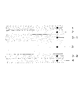
The figures show inventive layer configurations and a bending device.
Figure 1 shows a layer configuration having a cover layer (1), an upper
intermediate layer
(2), a lower intermediate layer (3-1), a substrate layer (3), a rear cover (3-
2) and an
adhesion promoter layer (4).
Figure 2 shows a layer configuration having a cover layer (1), a lower
intermediate layer (3-
1), a substrate layer (3), a rear cover (3-2) and an adhesion promoter layer
(4).
Figures 3a to 3d show a bending device in a side view (figure 3a), in a top
view (figure 3b),
from behind (figure 3c) and in a perspective view (figure 3d).
Figures 4a to 4f show detailed views of this bending device along the
sectional planes
depicted in figure 4a. Sectional plane A-A: figure 4b; B-B: figure 4c; C-C:
figure 4d;
D-D: figure 4e; E-E: figure 4f.
Figures 5a to 5d show a forming shoe for a bending device according to figures
3a to 4f in
different views.
Method for the production of a substrate
A substrate is a two-dimensional multi-layered composite body, which includes
at least the
second intermediate layer (3-1) and the substrate layer (3). It is produced in
the extrusion or
co-extrusion method. The at least two-layered composite bodies according to
the invention
may be produced in a single-step method by means of adapter or nozzle co-
extrusion.
Thereby, the materials of the different layers are made flowable each in an
extruder by
thermal effects and are then combined in an adapter system or a multi-channel
nozzle or a
15
combination of both into said multi-layered substrate and ejected by the
nozzle, fed over a
polishing calendar and cooled. Cooling is usually effected by the semi-
finished products
being fed via a cooling track.
Cover layer (1)
The cover layer is composed of a surface-coating layer, polymerized by means
of UV
irradiation. Ultraviolet radiation, in brief ultraviolet or UV radiation, is
electromagnetic
radiation that is invisible for human beings and has a wavelength that is
shorter than that of
the light visible for human beings but longer than that of X-rays. This range
is situated
between 1 nm and 380 nm. The surface-coating layer is produced by applying and
curing the
surface-coating material according to the inventive method onto the substrate
in order to
represent the composite body according to the invention. In contrast to oil,
dispersion and 2-
component surface-coating materials, however, 100% surface-coating UV
materials do not
have any volatile ingredients. Neither water nor solvents are contained
therein. After curing,
UV-cured surface-coating materials, hence, are composed of virtually 100%
solids, as they
will cure due to UV irradiation, without losing essentially any mass weight.
Apart from
reactive moieties such as, e.g., acrylates (non-saturated polymers of the
acrylic acid) these
may include reactive diluents, photoinitiators, pigments, dyes, effect
pigments and other
additives. By using UV additives (UV absorbers and UV stabilizers) to an
extent of 0.01 to
% by weight, the materials and colorants used in the layers lying underneath
will be
protected against UV radiation, which is why colour retention as well as
continuous material
characteristics will be significantly improved over the time of use when
irradiated with UV
light. Furthermore, the cover layer or the surface-coating UV material,
respectively, may be
transparent or embodied with different colorants, respectively. In the surface-
coating layer,
there may also be included nanoparticles in order to improve various
characteristics. The
cover layer is applied onto the optional upper intermediate layer (2) or onto
the lower
intermediate layer (3-1) in the method according to the invention.
Optional upper intermediate layer (2)
The optional upper intermediate layer (2) between the substrate layer (3) and
the cover layer
(1) is composed of¨ if it is existent at all ¨ preferably polymethyl
methacrylate (PMMA),
impact-modified PMMA/HI-PMMA or a blend thereof. The optional intermediate
layer (2)
may be used if the substrate layer is composed of acrylonitrile-butadiene-
styrene terpolymer
(ABS), impact-modified polystyrene (PS), acrylonitrile-styrene-acrylic ester
(ASA) or
styrene co-polymers. The most important characteristics of PMMA are summarized
in Hans
Domininghaus, "Die Kunststoffe und ihre Eigenschaften" [Plastics and their
Properties],
edition 1998. p. 455 ¨481. PMMA is extremely suitable as an intermediate layer
material,
as it shows high hardness and
CA 2846488 2019-04-01
CA 02846488 2014-02-25
16
scratch resistance and is transparent. The increased hardness, in this
connection, is
advantageous as the cover layer (1) situated above is very thin but prevents,
however, in
combination with the hard upper intermediate layer (2) impressions in the case
of pressure-
like strain.
A high transparency of the upper intermediate layer (2) is advantageous as the
combination
of the transparent surface-coating cover material and the transparent
intermediate layer (2)
situated underneath and having the coloured substrate layer (3) will result in
increased
spatial perception, similar to that of back-coated glass.
In the range of visible light (380 nm to 780 nm) the spectral transmission of
the
thermoplastic material is in one embodiment variant at least 80% (preferably
at least 85%),
measured using colourless sample bodies according to ISO 13468-2 (as of: 1999)
at the layer
thickness selected for the composite body. It is only natural that the
thermoplastic material
may also be a blend of plastic materials. In the case that the theunoplastic
material is a
plastic blend, this plastic bland should have a spectral transmission in the
entire wavelength
range from 380 nm to 780 nm of at least 80%, measured using sample bodies
according to
ISO 13468-2 (as of 1999).
There may also be added colorants to the upper intermediate layer (2). It may
further be
necessary to add UV additives. The upper intermediate layer (2) is applied
onto the lower
intermediate layer (3-1) in the co-extrusion method.
Lower intermediate laver (3-1)
The lower intermediate layer (3-1) includes a thermoplastic polymer, and it
may include,
e.g., the same polymer as the substrate layer. In this case, there is to be
noted, for example,
acrylonitrile-butadiene-styrene terpolymers (ABS). In one embodiment variant
there is
provided that the lower intermediate layer (3-1) includes glycol-modified
polyethylene
terephthalate (PETG).
If PETG is used as a material for the further intermediate layer (3-1), then
this may realized
by colouring with colorants; the layer, however, may also be non-coloured.
There may
optionally be added UV additives. The lower intermediate layer (3-1), however,
does not
contain preferably any grinding material, recyclate or regenerate. As the
substrate layer (3)
constitutes the colour-bestowing layer and as the requirements of the
furniture industry
regarding colour consistency are rather increased, and as it is significantly
more difficult to
retain colour tolerance due to the addition of grinding material, recyclate or
regenerate, the
CA 02846488 2014-02-25
17
lower intermediate layer (3-1) serves to achieve the highest colour
consistency possible.
Therefore, in the lower intermediate layer (3-1) polymers are coloured
analogously to the
substrate layer (3), using appropriate colorants. It may further be required
to add UV
additives.
The essentially more voluminous substrate layer (3) thereby may be coloured
using
essentially lower concentrations or with less cost-intensive colorants than
the lower
intermediate layer (3-1). For this reason, there may also be used very
expensive colouring
materials, as the concentration thereof with regard to the overall thickness
of the co-extruded
composite body is a rather lower one.
Substrate laver (3)
The substrate layer (3) presents the largest percentage of the multi-layered
composite. There
are used thermoplastic polymers as materials. In the framework of the
invention, a
thermoplastic material is a plastic material, which may be deformed in a
thermoplastic way
within a certain temperature range. The thermoplastic formability is a
reversible process so
that the thermoplastic material may be brought into the formable state
repeatedly by cooling
and heating. Pure plastics (homopolymers, hetero- or co-polymers,
respectively) and plastic
blends (mixtures of different plastic materials) are summarized as
thermoplastic materials.
Preferably there may be used acrylonitrile-butadiene-styrene terpolymers
(ABS), impact-
modified polystyrene (PS), acrylonitrile-styrene-acrylic ester (ASA), styrene
co-polymers,
polyolefins such as polypropylene or polyethylene, polycarbonate, polyethylene
terephthalate (PET) or modified co-polymers such as glycol-modified
polyethylene
terephthalate PETG).
There may further be present a blend of plastics as a thermoplastic material,
or it may be
necessary, respectively, to add additional materials in order to achieve the
desired
characteristics. In any case, however, the thermoplast used is essentially
free of PVC.
The substrate layer may optionally include grinding material, recyclate or
regenerate (e.g., of
preceding production steps or the installation of the extrusion plant or edge
trimming). There
may be added colorants to the substrate layer (3); and it is necessary to
combine colorants of
most diverse types in order to adapt to the colour tones wished by the
customers. It may be
further required to add UV additives.
CA 02846488 2014-02-25
18
If the substrate layer is not configured in a mono-layered but rather in a
multi-layered way,
the embodiment is then configured so that there may be arranged a lower
intermediate layer
(3-1) between the cover layer (1) or the intermediate layer (2) and the
substrate layer (3).
This is preferably composed of the same polymer as the substrate layer (3), in
particular in
the case ABS. If polyethylene terephthalate (PET) or modified co-polymers such
as glycol-
modified polyethylene terephthalate (PETG) is used as a material, then there
is preferably
used glycol-modified polyethylene terephthalate (PETG) in the lower
intermediate layer (3-
1).
Rear cover (3-2)
At the side opposite to the cover layer (1) of the multi-layered composite
according to the
invention, there may be arranged a further optional rear-sided cover layer
(rear cover) (3-2).
This is essentially composed of the thermoplastic material, as described in
the substrate layer
(3); there is, however, herein also not added any grinding material, recyclate
or regenerate:
If the substrate layer (3) includes polyethylene terephthalate (PET) or
modified copolymers
such as glycol-modified polyethylene terephthalate (PETG), then the rear cover
(3-2) is
preferably and essentially composed of glycol-modified polyethylene
terephthalate (PETG).
Regardless of the raw materials, which are used in the rear cover (3-2), there
may be added
matting agents. Matting agents are in general additives, which have such
effects on the
surface of a coating so that the gloss grade thereof will decrease. There is
usually associated
therewith an increase of surface roughness, which will show an improved
processing
performance in the process about to follow, this is, lamination. Suitable
matting agents are
known to those skilled in the art and include, e.g., inorganic fillers, in
particular silica gel or
cross-linked polymers in bead form ("polymer beads"), preferably aerylate
beads. The
amount added is preferably between 0.1 and 5 % by weight.
If the rear cover (3-2) is composed of polymer blends, then there may also be
generated a
matted rear-side cover layer due to the morphology existent in the polymer
alloy, which has
the same positive effect on further processing as the addition of a matting
agent. For this
reason, an additional matting agent may be omitted in this configuration.
If the adhesion of the multi-layered composite according to the invention
having the
adhesion promoter / primer layer (4) is insufficient, then there could be
added chemical
adhesion promoters to the rear cover (3-2). This is especially used with
substrate layers on
the basis of polyolefins: examples thereof are ethylene-vinyl acetate co-
polymers in the case
CA 02846488 2014-02-25
19
of polyethylene, or maleic anhydride-grafted polypropylenes in the case of
polypropylene. In
both cases the polarity of the surface is increased by the co-monomers added,
resulting in
improved adhesion performance.
The optional rear cover (3-2) may be coloured by colorants, there is, however,
also the
possibility of not colouring this layer. There is further the possibility to
add antistatic
additives (also known as antistatic agents) to the optional rear cover (3-2).
"Antistatic
agents" is the term for substances, which, when added as additives, prevent or
weaken,
respectively, the static charge of articles. Antistatic agents are used in
order to prevent the
undesired effects of electrostatic charges, caused by mechanical friction.
Hence, electrostatic
charge may lead to undesired effects of attraction or repulsion or to sudden
electrical
discharges. Specific examples thereof would be the prevention of dust
attraction, hair
"standing straight out" or ignition of explosive mixtures by discharge sparks.
Especially
materials having a high electric resistance, such as, e.g., thermoplastic
materials, are affected
by this phenomenon and thus have to be provided with antistatic features.
It has been shown that furniture films, which are provided with additives of
this type,
become less statically charged and thus attract dust in an essentially lower
amount. Dust on
furniture films is enclosed during the lamination process between films and
MDF (medium-
density fibreboards) and leads to unattractive defects (waviness) on the
finished furniture
panel. According to the invention, all types of antistatic agents, which
essentially prevent the
attraction of dust in processing, may be added.
Also herein, there is being made use of the advantages of co-extrusion: The
essentially more
voluminous substrate layer (3) need not be provided with the additives or
colorants, which
are used in the optional rear cover (3-2). For this reason, also expensive
additives or
colorants may be used, as the concentration thereof with regard to the overall
thickness of
the co-extruded composite body is very low.
Adhesion promoter / primer layer (4)
On the rear side of the substrate layer (3) or of the rear cover (3-2) there
is optionally applied
an adhesion promoter layer (4). Therefore, the surface is subjected to surface
pre-treatment
by activation before the primer layer will be applied. This is realized, e.g.,
by corona
treatment, flame treatment, plasma treatment or fluorination. The primer /
adhesion promoter
is then applied onto this activated surface. A primer layer is understood in
general as a paint
coating or coating for improving the adhesion of adhesive layers. In the case
of furniture
CA 02846488 2014-02-25
films it serves to improve the adhesion to the wood plate, which is usually
composed of
MDF (medium-density fibreboards).
Colorants
Pigments, dyes or effect pigments are designated as colorants. The combination
of colorants
of the most varied types is necessary in order to adjust the colour tones
desired by the
customers.
In contrast to dyes, pigments are insoluble in the carrier medium. The term
"carrier medium"
designates the material, into which the pigment is introduced, e.g., a surface-
coating material
or a plastic material. Dyes and pigments belong to the group of colorants and
may be
inorganic or organic, coloured or non-coloured.
According to literature, Gunter Buxbaum, "Industrial Inorganic Pigments",
edition 1993,
page 207-224, effect pigments, as used in the lower intermediate layer (3-1),
may be
distinguished into two large classes, pearlescent pigments and metallic effect
pigments.
Pigments of this type may be used to achieve special visual effects; they may
also be used in
combination with normal pigments and/or dyes.
UV additives
The ultraviolet proportion of the sun light destroys chemical bonds in some
polymers in a
process called photodegradation. This will cause, due to chemical changes in
the polymer,
also changes in the chemical and physical performance. Cracks, discolouration,
colour
changes, e.g., are consequences and results of these reactions. In order to
prevent or delay
effects of this type, there may be added UV additives. Dependent on the mode
of action of
these UV additives, there is distinguished between UV absorbers and UV
stabilizers. UV
absorbers lead to an absorption of UV radiation, which moves through the
polymer, and
convert this to thermal energy. As an example of very effective absorbers,
there are to be
mentioned benzophenons. UV stabilizers inhibit free radicals, which are
developed by the
irradiation with UV radiation, and stop further degradation. As an example of
very effective
stabilizers, there are to be mentioned HALS (hindered amine light
stabilizers).
Exemplary embodiments
The invention is in the following explained by way of examples. To this end,
the materials,
which were among others thermoplastic, were manufactured in the co-extrusion
method
having a width of 1300 mm, and in the consequence, using the method according
to the
invention, composite bodies according to the invention were produced.
21
Example 1:
Cover layer (1): 11 gm UV-cured surface-coating material
Optional intermediate layer (2): 0.024 mm AltuglasTM V046 glass-clear PMMA
Intermediate layer (3-1): 0.059 mm StyronTM Magnum 3404 Natur ABS + colour
Substrate layer (3): 0.480 mm Styron Magnum 3404 Natur ABS + colour + 20%
accrued
grinding material
Optional rear-side cover layer (3-2): 0.031 mm 85% Styron Magnum 3404 Natur
ABS +
15% Styron Magnum XZ96515 ABS matt
Example 2:
Cover layer (1): 11 gm UV-cured surface-coating material
Intermediate layer (3-1): 0.061 mm Styron Magnum 3404 Natur ABS + colour
Substrate layer (3): 0.299 mm Styron Magnum 3404 Natur ABS + colour + 20%
accrued
grinding material
Optional rear-side cover layer (3-2): 0.030 mm 85% Styron Magnum 3404 Natur
ABS +
15% Styron Magnum XZ96515 ABS matt
Example 3:
Cover layer (1): 6 gm UV-cured surface-coating material
Optional intermediate layer (2): 0.024 mm Altuglas V046 glass-clear PMMA
Intermediate layer (3-1): 0.061 mm Styron Magnum 3404 Natur ABS + colour
Substrate layer (3): 0.380 mm Styron Magnum 3404 Natur ABS + colour + 30%
accrued
grinding material
Optional rear-side cover layer (3-2): 0.029 mm 85% Styron Magnum 3404 Natur
ABS +
15% Styron Magnum XZ96515 ABS matt
Characterization of the UV-cured surface-coating material used:
It includes, among others, 1,6-hexanediol diacrylate as well as
trimethoxyvinyl silane, in
small amounts triphenyl phosphite. Density is indicated with 1.14 g/m1 having
an output
viscosity of 0.15 ¨ 0.25 Pas at 25 C, measured using a rotation viscosimeter
according to
DIN 53019/ISO 3219, as of 1994.
CA 2846488 2019-04-01
CA 02846488 2014-02-25
22
From the tests of the examples 1 to 3, there may be derived the following
results:
Table 4: results of the tests for examples 1 ¨ 3.
Thickness Micro- Resistance Gloss 4) Haze 5) LW 6) SW I)
surface- scratch to
coating resistance chemical
layer 1) 2)
agents 3)
Example 1 11 3.9 5 87.4 9.8 0.8 , 0.2
Example 2 11 6.5 5 88.2 5.7 0.9 0.4
Example 3 6 15.9 5 86.3 14.3 1.0 0.3
1) Thickness of the surface-coating layer: [ ] = um, measured using microscope
Nikon
Eclipse ME600, on thin-sections
2) [] = % micro-scratch resistance, measured following prEN 16094 as of 2010-
05-15:
"Laminate floor coverings ¨ Test method for the determination of micro-scratch
resistance", characterized by the loss of gloss at 20 before strain minus
gloss at 20 after
strain, indicated in percent
3) Resistance to chemical agents, measured according to DIN EN 12720 as of
July 2009:
"Furniture - Assessment of surface resistance to cold liquids" using acetone
as a test
liquid for a test duration of 1 h
4) Gloss in GLE (gloss units) according to ()NORM EN ISO 2813, as of 199-06-
01:
"Coatings - Determination of the reflectometer value of coatings at 20 , 60
and 85 ",
measuring device: Haze Gloss by Byk Gardner, angle of observation: 20
5) Haze: according to ONORM EN ISO 13803, as of 2004-09-01: Coatings -
Determination
of the haze of coatings at 20 , measuring device: Haze Gloss by Byk Gardner
6) LW: Long wave, measured using measuring device Wave Scan Plus by Byk
Gardner
7) SW: Short wave, measured using measuring device Wave Scan Plus by Byk
Gardner
Bendin2 device:
The figures 3a to 4f show a bending device 11 according to the invention for a
composite
body of the type mentioned above. The figures 5a to 5d show the associated
forming shoe
20. The figures 3a to 5d are in the following described together, as they each
show one
embodiment example in different views. The bending device 11 has a conveying
device 12,
13 for the composite body 15 and is composed of a roller table 12 and a roller
beam 13,
between which there is conveyed a wooden plate 14 having a composite body 15
arranged
on the surface thereof. In total three heating devices 16, 17, 18 are
responsible for heating
the area 23 of the composite body 15 to be bent. The forming shoe 20 is
extended along the
conveying device 12, 13 of the composite body 15, wherein the forming shoe 20
has a
CA 02846488 2014-02-25
23
bending edge 21, the inclination of which increases with regard to the
conveying plane E of
the conveying device 12, 13 along the conveying direction. The bending edge 21
is clearly
recognizable in the figures 5a to 5d, in particular in the detailed view F
(figure 5b). Therein
is shown the first area of the bending edge 21', in which the inclination with
regard to the
conveying plane E of the conveying device 12, 13 is 0 . The inclination will
constantly
increase in the conveying direction, wherein the bending edge 21 is adjusted
to the desired
angle of inclination from here 90 in the area 21". In the area 21", the
bending edge 21 is
curvilinear and forms a transition from the inclination of 0 to the desired
inclination.
In the figures 4b to 4f, the forming shoe 20 is visible in practical use at
various positions.
The composite sheet 15 protrudes beyond the edge of the wooden plate 14 by the
area 23 to
be bent. At the beginning of the bending device 11, the area 23 to be bent is
only heated. The
forming shoe 20 with the bending edge 21 is situated in parallel to the
composite sheet 15
(figure 4b). With increasing bending (figures 4c, 4d, 4e), the angle of
inclination of the area
23 to be bent will become larger with regard to the conveying plane E by the
guiding of the
bending edge 21 or also with regard to the plane of the composite sheet,
respectively. At the
end of the bending edge 21 (figure 41), the area 23 to be bent is completely
bent (herein
about 90 ) and is flush with the lateral front edge of the wooden plate 14.
The heating devices 16, 17, 18 provide for the heating of the composite sheet
15, wherein the
heating device 18 has already been assigned to the forming shoe 20. After
heating, it should
be avoided that the composite sheet 15 cools too quickly during the forming
process, this is
before and during the bending process energy is to be introduced in order to
prevent surface
cracks. The heating devices 16, 17, 18 are hot air heaters. The area 23 to be
bent may be
heated using the nozzles of the air heater.
There is further provided a temperature measuring device 22, which is arranged
so that the
temperature of the area of the composite body to be bent may be determined.
The
temperature measuring device 22 includes a pyrometer. Therewith, the surface
temperature
of the composite body is measured. A control device that is not shown is
connected with the
heating device 16, 17, 18 for the forming shoe 20 and controls this in
dependency on the
temperature determined by the temperature measuring device 22. If the
temperature is too
low, there may be additionally heated.
The forming shoe 20 further has a levelling area 24, which serves to level any
unevenness or
waviness of the composite body.