Note: Descriptions are shown in the official language in which they were submitted.
CA 02846648 2014-02-25
WO 2013/036438
PCT/US2012/053262
1
CROSS RUNNER CONNECTOR AND MAIN RUNNER RECEIVING HOLE
BACKGROUND OF THE INVENTION
This application claims the priority of U.S. Provisional
Application No. 61/532,755, filed September 9, 2011.
The invention relates to suspended ceiling grid and, more
particularly, to cross runner connections.
PRIOR ART
Suspended ceiling grid is typically constructed with main
runners that are relatively long and cross runners that
intersect the main runners and are relatively short. The main
runners are formed with holes along their length strategically
spaced to receive connectors on the ends of the cross runners.
Typically, the grid runners are referred to as tees because of
their most common cross-sectional shape. U.S. Patents 5,517,796
and 5,761,868 illustrate examples of cross runner end
connectors.
SUMMARY OF THE INVENTION
The invention provides an improved cross runner connector
or clip and main tee connector receiving hole. The connector
and receiving hole achieve a single runner joint that has a much
higher pull out or tensile resistance than prior art systems and
can be easily disassembled from either a single or double runner
connection.
The invention utilizes a unique locking tab that greatly
improves single runner connection performance. The geometry of
the inventive tab resists buckling or folding of the tab when
the associated runner is subjected to high tensile loads.
Additionally, the inventive tab, by virtue of its geometry and
spring characteristics reduces free play in a joint. The single
CA 02846648 2014-02-25
WO 2013/036438
PCT/US2012/053262
2
connection joint made by the inventive connector is less prone
to accidental release in a cantilever condition where only one
end of a cross runner is supported.
The geometry of the connector and receiving hole permits
the connector to be easily released from either a single
connector joint or a connector-to-connector joint. The release
can be effected without damage or physical alteration to either
the main runner or the cross runner. This non-destructive, non-
altering release allows a cross runner to be disassembled and
reconnected multiple times without loss of function.
BRIEF DESCRIPTION OF THE DRAWINGS
FIG. 1 is a perspective side view of the connector of the
invention;
FIG. 2 is a fragmentary side view of a main or through
runner having a connector receiving hole of the invention;
FIG. 3 is a side view of the connector and an end portion
of a cross runner;
FIG. 4 is a perspective fragmentary view of a pair of
opposed connectors assembled in a common hole in a main runner;
FIG. 5 is a side view of a pair of joined connectors;
FIG. 6 is a top view of the pair of joined connectors; and
FIG. 7 is an end view of a connector assembled in a main
runner hole with an opposed connector.
DESCRIPTION OF THE PREFERRED EMBODIMENT
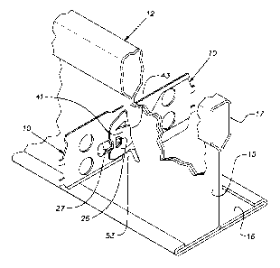
A connector or clip 10 of the invention is permanently
assembled on an end of a cross runner or tee 11 and is effective
to join the cross tee to a main runner or tee 12 at a hole 13 of
the invention in the main tee. The connector 10 is also capable
of joining with an identical connector of an opposed cross
runner or tee 11 inserted in a hole 13 from an opposite side of
CA 02846648 2014-02-25
WO 2013/036438
PCT/US2012/053262
3
the main runner 12. As is customary, main runners 12 are
arranged on parallel lines spaced apart by a plurality of cross
runners 11 spaced along the main runners on centers determined
by the location of the holes 13 on the main runners. Typically,
the runners 11, 12 are manufactured by roll forming sheet metal
into the desired cross section. A cross runner 11 has an
identical connector 10 fixed on each of its ends. The
connectors or clips 10 are mounted to a web 15 of the cross
runner 11 that extends between a lower flange 16 and an upper
hollow reinforcing bulb 17. The main runner 12 has holes 13
located along its length spaced at, for example, 6 inches, or
the industry metric equivalent thereof, and are used to
establish a corresponding grid module of 2 foot or 4 foot. In 2
foot by 2 foot modules, a 4 foot cross runner, as is customary,
can serve as a main or through runner for a 2 foot cross runner;
a hole 13 is located at the mid-length of the 4 foot through
(cross) runner.
The connector 10 is stamped from high strength, hard sheet
metal and exhibits spring characteristics. The side profile of
the connection 10 is roughly rectangular, having a length
greater than its height. Upper and lower margins 21, 22 of the
connector 10 are offset from a major central plane of the
connector to impart stiffness. Two holes 23 through the body of
the connector 10 receive material of a cross runner that is
folded or crimped over edges of the holes to fix the connector
onto an end of a cross runner 11.
The connector 10 has a pair of opposed projections 26, 27
spaced by an opening that forms edges 28, 29. The projections
26 are arranged to receive a strip or band 31 of material at the
leading edge of an identical clip. A D-shaped hole 32 is
proportioned to receive a forward projection 26 of a mating
connector. Additionally, where the connector 10 is joined to an
CA 02846648 2014-02-25
WO 2013/036438
PCT/US2012/053262
4
identical connector, the edge 29 of the rearward projection 27
engages a lead end 34 of the identical clip to resist
compressive longitudinal forces in the associated runners 11.
An embossment 36 in the lead or forward end of a connector
10 facilitates coupling of a pair of clips being forced together
in a common hole 13, as discussed below, by riding over the
forward projection 26 of the opposed connector 10.
A locking tab 41 is stamped and permanently bent out of a
main plane of the clip body to a side opposite that on which the
projections 26, 27 exist. The tab 41, which in the illustrated
arrangement is planar, is attached to the main clip body at a
bend line 42 which is inclined forwardly from bottom to top. A
generally rearwardly facing free edge of the tab is stepped or
offset so that an upper part of the edge 43 lies forward of a
lower part 44. The upper part or zone 43 of the edge is
inclined forwardly from bottom to top. The connector 10 has a
generally vertical notch 46 on its forward upper edge, each side
of the notch diverging, for example, at about 5 degrees from the
vertical. The lower part 44 of the free edge of the locking tab
41 is rearward of an imaginary vertical plane, transverse to the
plane of the main body of the connector 10, that is tangent to a
forward edge 47 of the notch 46. A rearward edge 48 of the
notch 46 lies generally in a vertical plane transverse to the
connector body common with a vertical lower abutment edge 49 of
the connector profile.
The cross runner connector receiving hole 13 is stamped in
the web 15 of the through or main runner 12. The hole 13 has a
shape similar to the capital letter A, being symmetrical about a
vertical axis. A narrow top 51 of the hole 13 has a width
adequate to receive the thickness of two connectors 10 with
moderate clearance. A notch or shallow slot 52 at the bottom of
the hole 13, between a pair of abutments 53 is similarly
CA 02846648 2014-02-25
WO 2013/036438
PCT/US2012/053262
proportioned to receive a double thickness of a connector body
with moderate clearance. The distance between the top 51 of the
hole 13 and the top of the abutments 53 is greater than the
distance between the bottom of a connector notch 46 and a lower
5 edge 54 of a forward end of the connector 10. Opposite sides or
edges 56 of the hole 13 are arcuate and convex.
A cross runner or tee 11 is assembled to a main runner or
tee 12 by inserting its end connector 10 in an appropriate hole
13. The body of the connector 10 is inserted in the center of
the hole 13 so that its lower edge 54 is in the central notch
52. The cross runner 11 is pushed towards the main runner 12
until the connector profile edges 48 and 49 abut the surface of
the web 15 surrounding the hole 13. This insertion motion
causes the tab 41 to be forced towards the main body of the
connector 10 by a camming action developed by interference
between the tab and a side 56 of the hole 13. Before the
connector edges 48 and 49 contact the web 15, the forwardmost
part of the first tab edge 43 will reach the far side of the web
15 and the tab 41 will spring towards its free state. This
spring action drives the forward part of the edge 47 outward of
the boundary of the adjacent side 56 of the hole 13 thereby
locking the connector 10 in the hole. The tab 41 is
proportioned so that its trailing part behind the forward edge
43 and including the rearward edge 44 cannot pass through the
hole 13 before motion of the connection is stopped by abutment
of the edges 48 and 49 with the main runner web 15. The
resilient spring action of the tab 41 causes the slightly
inclined forward edge 43 at the free edge of the tab 41 working
against the convex hole side 56 to draw the connector 10 tight
against the main runner 12.
The distal trailing part of the tab 41, since it cannot
pass through the hole 13 and is laterally confined by the hole
CA 02846648 2014-02-25
WO 2013/036438
PCT/US2012/053262
6
prevents the tab from buckling or folding outward, i.e.
overbending from the main body of the connector 10 when even a
high tensile load is applied to the associated cross runner 11.
The connector 10 has demonstrated a resistance to such tensile
loads of 5 or more times than that of currently available prior
art products.
Circumstances occur where the opposite end of a cross
runner 11 is unsupported so that the cross runner is in a
cantilever condition. This condition can occur, for example,
where an opposite end was improperly or not fully installed on a
parallel main tee and then falls off the parallel main tee.
Another circumstance occurs where an installer inserts a
connector 10 in a main runner hole 13 and allows the cross
runner to hang with its opposite end temporarily unsupported
during erection of a grid. In these circumstances, the notch 46
serves to cooperate with the locking tab 41 to maintain the
joint or coupling of the cross runner with a more reliable
coupling than is experienced with prior art connectors.
A second connector 10 of an opposing cross runner 11 can be
assembled in a hole 13 from the side opposite the first
connector. A second connector 10 is placed laterally against
the lead end of the first connector and pushed into the center
hole slot 52 until its abutment edges 48 and 49 contact the web
15 of the main runner 12. In this position, the connectors 10
establish a strong connector-to-connector lock with the forward
band 31 of each connector captured in the pocket between
opposing projections 26, 27 of the other connector. The locking
tab 41 of the second connector 11 works as previously described.
The lateral compression on both locking tabs 41, developed by
their confinement in the hole 13, serves to maintain the
connectors in mutual inter-engagement.
CA 02846648 2014-02-25
WO 2013/036438
PCT/US2012/053262
7
The connector 10 can be easily released from a hole 13
without tools whether or not coupled to an opposing connector.
This release is accomplished by holding the main runner 12 in
one hand, raising the cross runner to be released so that the
top edge of the hole 13 is fully received in the cantilever
notch 46 on the top of the associated connector 10 and then
twisting the cross runner 11 so that the connector pivots in the
hole 13 away from any opposed connector. This pivoting motion
moves the connector 10 towards the hole side 56 compressing the
associated tab 41. The convex character of the hole side 56
focuses the reaction force developed by the hole side on the
trailing portion of the tab 41. The tab 41 is forced towards
the plane of the main body of the connector 10 until the locking
edge 43 is free of the main runner web area at the edge of the
hole 13. In this orientation of the connector 10, the locking
strips or bands 31 of any opposed connectors 10 are released
from the restriction of opposing projections 26, 27. The
twisted connector 10 can now be withdrawn from the hole 13 to
release its cross runner 11. No damage or permanent deformation
is incurred either by the connector 10 or the main runner 12.
The connector 10 can, therefore, be reassembled and disassembled
repeatedly.
It should be evident that this disclosure is by way of
example and that various changes may be made by adding,
modifying or eliminating details without departing from the fair
scope of the teaching contained in this disclosure. The
invention is therefore not limited to particular details of this
disclosure except to the extent that the following claims are
necessarily so limited.