Note: Descriptions are shown in the official language in which they were submitted.
CA 02846794 2014-02-26
WO 2013/037817 PCT/EP2012/067822
ANNULAR BARRIER WITH AXIAL FORCE MECHANISM
Field of the invention
The present invention relates to an annular barrier to be expanded in an
annulus
between a well tubular structure and an inside wall of a borehole downhole for
providing zone isolation between a first zone and a second zone of the
borehole,
the annular barrier comprising a tubular part extending in a longitudinal
direction
for mounting as part of the well tubular structure; an expandable sleeve
surrounding the tubular part and defining a space being in fluid communication
with an inside of the tubular part; a first fluid passage for letting fluid
into the
space to expand the sleeve; and a connection unit comprising a connection part
slidably connected with the tubular part. Further, the present invention
relates to
a system comprising an annular barrier and a method of expanding an annular
barrier.
Background art
In wellbores, annular barriers are used for different purposes, such as for
providing a barrier for flow between an inner and an outer tubular structure
or
between an inner tubular structure and the inner wall of the borehole. The
annular barriers are mounted as part of the well tubular structure. An annular
barrier has an inner wall surrounded by an annular expandable sleeve. The
expandable sleeve is typically made of an elastomeric material, but may also
be
made of metal. The sleeve is fastened at its ends to the inner wall of the
annular
barrier.
Multiple annular barriers may be used to seal off a zone between an inner and
an
outer tubular structure or a well tubular structure and the borehole. A first
annular barrier is expanded on one side of the zone to be sealed off, and a
second annular barrier is expanded on the other side of that zone, whereby the
zone is sealed off.
An annular barrier may be set using a pressurised fluid which is injected into
the
well or into a limited part of the well. Hereby, the expandable sleeve of the
annular barrier is expanded to engage with an outer tubular structure or the
CA 02846794 2014-02-26
WO 2013/037817 PCT/EP2012/067822
2
inner wall of the borehole. The pressure envelope of a well is governed by the
burst rating of the tubular and the well hardware etc. used within the well
construction. When the expandable sleeve is expanded by increasing the
pressure within the well, the burst rating of a well defines the maximum
pressure
that can be applied. It is desirable to minimise the expansion pressure
required
for expanding the sleeve to minimise the exposure of the well to the expansion
pressure.
To reduce the expansion pressure of the annular barrier, the thickness of the
expandable sleeve may be decreased. However, this impairs the strength of the
expandable sleeve and the maximum expanded size of the sleeve. Further, the
sleeve may collapse or rupture before the desired expanded size of the sleeve
is
reached. A frequently occurring reason for ruptures of expandable sleeves is
inexpedient thinning of the sleeve material during expansion. Thinning of the
sleeve material is an important property of the expandable sleeve, but too
much
thinning, e.g. in a local region of the sleeve, will cause the annular barrier
to
malfunction.
Summary of the invention
It is an object of the present invention to wholly or partly overcome the
above
disadvantages and drawbacks of the prior art. More specifically, it is an
object to
provide an improved annular barrier wherein inexpedient thinning of the sleeve
is
avoided.
The above objects, together with numerous other objects, advantages, and
features, which will become evident from the below description, are
accomplished
by a solution in accordance with the present invention by an annular barrier
to be
expanded in an annulus between a well tubular structure and an inside wall of
a
borehole downhole for providing zone isolation between a first zone and a
second
zone of the borehole, the annular barrier comprising:
- a tubular part extending in a longitudinal direction for mounting as part
of the
well tubular structure,
- an expandable sleeve surrounding the tubular part and defining a space
being
in fluid communication with an inside of the tubular part,
- a first fluid passage for letting fluid into the space to expand the
sleeve,
CA 02846794 2014-02-26
WO 2013/037817 PCT/EP2012/067822
3
- and a connection unit comprising a connection part slidably connected with
the
tubular part,
wherein the connection unit further comprises a stationary part fixedly
connected
with the tubular part and an actuation mechanism adapted to induce an axial
force on the first end of the expandable sleeve, whereby the connection part
is
displaced in the longitudinal direction towards a second end of the expandable
sleeve connected with the tubular part.
An advantage in this respect is that inexpedient thinning of the expandable
sleeve is avoided by simultaneously expanding the expandable sleeve by
injecting a hydraulic fluid into the space defined by the expandable sleeve
and
displacing the connection part to move one end of the expandable sleeve
towards
the other end.
In one embodiment, the connection part may constitute part of the actuation
mechanism.
The annular barrier as described above may further comprise two connection
units each comprising a connection part connected to a first and a second end
of
the expandable sleeve, respectively.
Moreover, the actuation mechanism may comprise a pressure chamber at least
partly defined between a face of the connection part and a face of the
stationary
part.
Also, the annular barrier as described above may comprise a second fluid
passage for letting fluid into the pressure chamber of the actuation mechanism
to
push the connection part in the longitudinal direction.
In addition, the second fluid passage may be provided with a check valve.
The annular barrier as described above may further comprise a fluid bypass
passage for providing fluid communication between the pressure chamber and
the space defined by the expandable sleeve when the connection part has been
displaced in the longitudinal direction.
CA 02846794 2014-02-26
WO 2013/037817 PCT/EP2012/067822
4
Additionally, the fluid bypass passage may be blocked by the connection part
before the connection part is displaced in the longitudinal direction.
In one embodiment, the first fluid passage may be provided in the connection
part, thereby fluidly connecting the space defined by the expandable sleeve
and
the pressure chamber of the actuation mechanism.
By arranging the first fluid passage in the connection part, the flow through
the
first fluid passage may be adjusted to control the pressure inside the
pressure
chamber and thus the force induced on the connection part and the first end of
the expandable sleeve. By being able to better control the force induced on
the
connection part, inexpedient thinning of the expandable sleeve may be avoided.
Also, the first fluid passage may be provided with a check valve.
Moreover, the first fluid passage may be provided with a pressure regulated
valve
preventing fluid flow into the space defined by the expandable sleeve when the
pressure inside the space exceeds a predetermined threshold value.
Hereby, rupture of the expandable sleeve may be prevented by the pressure
regulated valve because the pressure inside the space is always kept within
the
limits of the expandable sleeve.
Further, the actuation mechanism described above may comprise a hydraulic
pump fluidly connected with the pressure chamber, the hydraulic pump being
adapted to push the connection part in the longitudinal direction by pumping a
hydraulic fluid into the pressure chamber.
In addition, the actuation mechanism may comprise a pressure-intensifying
means comprising an inlet being in fluid communication with the inside of the
tubular part and an outlet being in fluid communication with the pressure
chamber, whereby a hydraulic fluid is supplied to the pressure chamber to push
the connection part in the longitudinal direction.
By the annular barrier comprising a hydraulic pressure intensifier,
pressurised
fluid inside the tubular part can be used to provide a pressurised fluid
inside the
pressure chamber at a pressure substantially higher than the pressure of the
fluid
CA 02846794 2014-02-26
WO 2013/037817 PCT/EP2012/067822
inside the tubular part. Hereby, the expansion pressure of the hydraulic fluid
injected inside the tubular part may be reduced for the benefit of other well
hardware deployed in the well.
5 Moreover, the pressure-intensifying means may further comprise a
reciprocating
piston and a pilot control valve adapted to change the direction of flow of
the
hydraulic fluid.
Also, the reciprocating piston of pressure-intensifying means may have a first
end face and a second end face, the first end face having a surface area Al
larger than a surface area A2 of the second end face.
Additionally, the surface area of the first end may be between 2 and 6 times
larger than the surface area of the second end.
Hereby, the piston is capable of intensifying the pressure applied to the
first end
face to a higher pressure applied by the second end face on the fluid inside
the
pressure chamber.
Further, the actuation mechanism may comprise a pressure vessel containing a
compressed propellant adapted to push the connection part in the longitudinal
direction by providing an excess pressure in the pressure chamber upon
activation.
More specifically, the propellant may be nitrogen, neon, argon, krypton,
xenon,
oxygen or air.
Moreover, the pressure vessel may be activated by a sensor sensing movement
of the connection part when the expandable sleeve starts to expand.
Further, the sensor may comprise a shear pin being broken by the movement of
the connection part.
In one embodiment, the actuation mechanism may comprise a rod connected
with the connection part to push the connection part in the longitudinal
direction.
CA 02846794 2014-02-26
WO 2013/037817 PCT/EP2012/067822
6
More specifically, the actuation mechanism may comprise a hydraulic pump, the
hydraulic pump being adapted to displace the rod by means of hydraulic
pressure, whereby the connection part is pushed in the longitudinal direction.
Also, the actuation mechanism may comprise a linear actuator comprising an
electrical motor, the linear actuator being adapted to push the connection
part in
the longitudinal direction.
The linear actuator described above may comprise a spindle rotated by the
electrical motor.
In one embodiment, the connection unit may further comprise a piston part
slidably connected with the tubular part, the piston part being arranged
between
the connection part and the stationary part, the pressure chamber being at
least
partly defined between a face of the piston part and the face of the
stationary
part, whereby the piston part is adapted to push the connection part in the
longitudinal direction.
Hereby, the piston part may be moved in the longitudinal direction away from
the
connection part without affecting the position of the connection part.
Specifically, the piston part may be connected with the rod.
Also, the piston part may be connected with the linear actuator.
In a further embodiment, the annular barrier may comprise a sensing mechanism
adapted to register when the pressure in the tubular part exceeds a
predetermined threshold value in order to subsequently activate the actuation
mechanism to induce an axial force on the connection part.
Such a sensing mechanism may comprise a rupture disc.
Also, the sensing mechanism may comprise a strain gauge.
Further, the annular barrier may comprise a sensor adapted to register
movement of the connection part to activate the actuation mechanism, whereby
an axial force is induced on the connection part.
CA 02846794 2014-02-26
WO 2013/037817 PCT/EP2012/067822
7
Additionally, the sensor may comprise a shear pin.
Alternatively, the sensor may comprise a magnet contact measuring movement
of the connection part.
Also, the sensor may be adapted to measure a pulling force being applied to
the
connection part.
The present invention further relates to a well system comprising the well
tubular
structure and the annular barrier as described above.
Finally, the present invention relates to a method for expanding the annular
barrier as described above in an annulus between a well tubular structure and
an
inside wall of a borehole downhole, the method comprising the steps of:
- at least partially expanding the expandable sleeve by letting fluid into the
space
defined by the expandable sleeve,
- inducing an axial force on the connection part where to one end of the
expandable sleeve is connected, and
- expanding the expandable sleeve until the sleeve seals against the inside
wall
of the borehole.
Also, the method may comprise the step of monitoring the pressure built up
inside the space defined by the expandable sleeve.
Further, the axial force may be induced on the expandable sleeve during
expansion of the expandable sleeve.
Brief description of the drawings
The invention and its many advantages will be described in more detail below
with reference to the accompanying schematic drawings, which for the purpose
of
illustration show some non-limiting embodiments and in which
Fig. la shows an annular barrier with one end of the expandable sleeve being
connected to a slidable connection part and the other end being connected to a
fixed connection part,
CA 02846794 2014-02-26
WO 2013/037817 PCT/EP2012/067822
8
Fig. lb shows an annular barrier with both ends of the expandable sleeve being
connected to a connection part slidably connected with the tubular part,
Fig. 2a shows a connection unit comprising a pressure chamber and an
expandable sleeve when the annular barrier is in an unset condition,
Fig. 2b shows the connection unit and the expandable sleeve of the previous
figure when the annular barrier is in a set condition,
Fig. 3a shows a connection unit comprising a connection part and a piston part
and an expandable sleeve when the annular barrier is in an unset condition,
Fig. 3b shows the connection unit and the expandable sleeve of the previous
figure when the annular barrier is in a set condition,
Fig. 4a shows a connection unit comprising a rod and an expandable sleeve when
the annular barrier is in an unset condition,
Fig. 4b shows the connection unit and the expandable sleeve of the previous
figure when the annular barrier is in a set condition,
Fig. 5 shows a connection unit comprising a fluid passage providing fluid
communication between the pressure chamber and the space defined by the
expandable sleeve,
Fig. 6 shows a fluid bypass passage for providing fluid communication between
the pressure chamber and the space defined by the expandable sleeve,
Fig. 7 shows a connection unit comprising a hydraulic pump adapted to pump a
hydraulic fluid into the pressure chamber,
Fig. 8 shows a connection unit comprising a pressure intensifier adapted to
supply a hydraulic fluid into the pressure chamber,
Fig. 9 shows a connection unit comprising a pressure vessel adapted to push
the
connection part in the longitudinal direction,
CA 02846794 2014-02-26
WO 2013/037817 PCT/EP2012/067822
9
Fig. 10 shows another embodiment of a connection unit comprising a connection
part slidably connected with the tubular part,
Fig. 11 shows a schematic illustration of the connection unit comprising the
pressure intensifier shown in Fig. 8,
Fig. 12 shows a schematic illustration of a connection comprising a hydraulic
piston adapted to displace the connection part in the longitudinal direction,
and
Fig. 13 shows a well system comprising the well tubular structure and the
annular barrier.
All the figures are highly schematic and not necessarily to scale, and they
show
only those parts which are necessary in order to elucidate the invention,
other
parts being omitted or merely suggested.
Detailed description of the invention
Fig. la shows an annular barrier 1 to be expanded in an annulus 2 between a
well tubular structure 3 and an inside wall 4 of a borehole 5 downhole or an
inside wall of another kind of well tubular. The tubular structure 3 may be a
production casing. The annular barrier 1 comprises a tubular part 6 mounted as
part of the well tubular structure 3. The tubular part 6 has a longitudinal
axis 40
coaxial with the longitudinal axis of the well tubular structure 3. The
annular
barrier 1 comprises an expandable sleeve 7 surrounding the tubular part 6 and
defining a space 30 which is in fluid communication with an inside 64 of the
tubular part 6. Each end 9, 10 of the expandable sleeve 7 is connected with
the
tubular part 6, the first end 9 end being slidably fastened in relation to the
tubular part and the second end 10 being fixedly fastened in relation to the
tubular part by a stationary connection part 13.
The annular barrier 1 has a first fluid passage 61 for letting fluid into the
space
30 to expand the expandable sleeve 7, the first fluid passage 61 being
arranged
in the tubular part 6 so that the fluid is let directly into the space 30. The
first
fluid passage 61 is for purposes of simplicity only shown in cross section,
but it is
to be regarded as one or a plurality of first fluid passages arranged around
the
periphery of the tubular part. A valve, such as a one-way valve, a flow
control
CA 02846794 2014-02-26
WO 2013/037817 PCT/EP2012/067822
valve, a pressure-regulating valve, etc, may be arranged in the first fluid
passage
61. Further, the annular barrier comprises a connection unit 120 comprising a
connection part 12 slidably connecting one end of the expandable sleeve with
the
tubular part, a stationary part 16 fixedly connected with the tubular part and
an
5 actuation mechanism 20 adapted to induce an axial force on the first end
of the
expandable sleeve in order to prevent unnecessary thinning of the sleeve. The
actuation mechanism will be described in more detail below. The first end 9 of
the expandable sleeve is connected with the connection part 12 so that the
part
of the sleeve is moved in the longitudinal direction when the connection part
12
10 is displaced accordingly.
Fig. lb shows another embodiment of an annular barrier wherein each end 9, 10
of the expandable sleeve 7 is slidably fastened in relation to the tubular
part 6.
This is achieved by the annular barrier comprising two connection units 120
similar to the connection unit described above. Accordingly, the first end 9
and
the second end 10 of the expandable sleeve are connected with a slidable
connection part 12. In the following, various embodiments of the invention
will be
disclosed without regard for how each end 9, 10 of the expandable sleeve 7 is
connected with the tubular part. Thus, what is disclosed may be applied
regardless of whether one or both ends of the expandable sleeve is/are
slidably
connected with the tubular part.
The annular barrier is mounted as part of a well tubular structure 3 shown in
Fig.
13 and activated or set by injecting a hydraulic fluid into the well tubular
structure 3. Hereby, the expandable sleeve is expanded in a radial direction
by
the pressure of the hydraulic fluid, while at the same time one or both ends
of
the expandable sleeve is moved in the longitudinal direction by a force
generated
by the actuation mechanism 20.
The fluid may be injected locally in a defined section of the well tubular
structure
3 or by pressurising the entire well tubular structure 3. Local injection may
be
conducted in a number of ways understood by those skilled in the art. One way
is
to lower a drill pipe with circumferential packers into the well tubular
structure
and position the packers on opposite sides of the first fluid passages for
letting
fluid into the space 30 to expand the sleeve. Subsequently, a fluid is
injected
through the drill pipe into a space between the packers, whereby fluid enters
the
space through the first fluid passages to activate and set the annular barrier
1.
CA 02846794 2014-02-26
WO 2013/037817 PCT/EP2012/067822
11
Another way of conducting local injection is by using a well tool, such as a
downhole tractor, comprising a pump. Such a tool may be lowered into the well
tubular structure 3 via wireline and be connected directly to the first fluid
passage. The well tool may inject fluid already present in the well or fluid
carried
by the tool.
Figs. 2a and 2b show an actuation mechanism comprising a pressure chamber
21. The pressure chamber is positioned between the connection part 12 and the
stationary part 16 and is at least partly defined by a face 121 of the
connection
part and a face 161 of the stationary part. Only a cross section of the
actuation
mechanism is shown in the figure, but the connection part and the stationary
part are to be regarded as revolving parts of a substantially tubular
extension
and encircling the tubular part 6. However, it is also to be understood by
those
skilled in the art that the connection part and the stationary part may be
divided
into a number of individual parts arranged around the periphery of the tubular
part while remaining within the scope of the present invention. Thus, the
pressure chamber 21 may be one contiguous chamber or be divided into several
isolated chambers encircling the tubular part. In the following, reference
will only
be made to one pressure chamber even though the annular barrier may comprise
several independent pressure chambers operated in a uniform way.
The pressure chambers 21 of Figs. 2a and 2b are in fluid communication with
the
inside 64 of the tubular part via second fluid passages 62. When hydraulic
fluid is
injected into the pressure chamber, a force is exerted on the face 121 of the
connection part, whereby the connection part is displaced in the longitudinal
direction away from the stationary part 16. To provide a fluid-tight seal
between
the tubular part 6 and the connection part, one or more sealing members 122,
such as o-rings or the like, may be arranged in recesses in the connection
part.
Similarly, one or more sealing members 162 may be arranged in one or more
recesses in the stationary part 16. In the shown embodiment, the connection
part 12 comprises a tubular skirt 123 protruding from an end of the connection
part opposite the expandable sleeve. The skirt extends to at least partly
cover
the stationary part 16 and constitutes a wall of the pressure chamber. The
tubular skirt 123 slides in relation to the stationary part when the
connection part
is displaced to prolong the pressure chamber. In Fig. 2a, the annular barrier
is
shown in a deactivated, unset condition, wherein the connection part and the
first
end of the expandable sleeve have not been displaced. The expandable sleeve is
CA 02846794 2014-02-26
WO 2013/037817 PCT/EP2012/067822
12
connected with the connection part using techniques understood by those
skilled
in the art, for which reason this will not be further described.
In Fig. 2b, the annular barrier is shown in an activated and set condition,
wherein
the connection part and the first end of the expandable sleeve have been
displaced in the longitudinal direction towards the opposite end of the
expandable
sleeve and away from the stationary part. The pressure chamber has been
considerably prolonged, and an outer face 71 of the expandable sleeve 7 abuts
the inside wall 4 of a borehole 5 downhole or, alternatively, an inside wall
of
another well tubular structure. Thereby, a section 22 of the annulus
surrounding
the tubular structure 3 is isolated from the remainder of the annulus 2. A
first
zone 221 of the borehole is thus isolated from a second zone 222 of the
borehole,
as shown in Fig. 13.
By simultaneously injecting a hydraulic fluid into the space defined by the
expandable sleeve and displacing the connection part to move at least one end
of
the expandable sleeve towards the other end, inexpedient thinning of the
expandable sleeve is avoided. The degree of displacement of the connection
part
is balanced according to the size of the expandable sleeve, material
properties,
desired expanded diameter of the expandable sleeve, etc.
When the annular barrier is in a set condition, the connection part 12 may be
permanently or temporarily locked in the displaced position, as show in Fig.
2b,
by locking means (not shown in Fig. 2b) known by those skilled in the art.
Fig. 3a shows a connection unit 120 comprising both the connection part 12 and
a piston part 14. In this embodiment, the expandable sleeve is connected with
the connection part, and a face 141 of the piston partly defines the pressure
chamber 21. Further, the piston part comprises a tubular skirt 123 similar to
that
of the connection part 12 described above. Both the connection part and the
piston part comprise sealing members 122, 142 for providing a fluid-tight
connection to the tubular part. The pressure chamber 21 has a functionality
similar to that of the pressure chamber described above, and when hydraulic
fluid
is injected into the pressure chamber 21 via the second fluid passages 62, a
force
is exerted on the face 141 of the piston part. Hereby, the piston part is
displaced
in the longitudinal direction away from the stationary part 16, whereby the
connection part is also displaced in the longitudinal direction.
CA 02846794 2014-02-26
WO 2013/037817 PCT/EP2012/067822
13
As shown in Fig. 3b, the piston part and the connection part are not
interconnected. Thus, the piston part can only affect the movement of the
connection part in the longitudinal direction away from the stationary part.
By the
piston part and the connection part not being connected, the piston part and
hence the actuation mechanism may be displaced after the annular barrier has
been set, without affecting the position of the connection part and the
expansion
of the expandable sleeve.
In Figs. 4a and 4b, a connection unit 120 comprising a rod 23 connected to the
connection 12 part is shown. The rod extends from the stationary part 16 to
displace the connection part 12 in the longitudinal direction. The rod may be
a
revolving part of substantially tubular extension, encircling the tubular part
6.
However, the annular barrier may alternatively comprise a number of individual
rods arranged around the periphery of the tubular part. In one embodiment, the
actuation mechanism for displacing the rods is comprised by a linear actuator
90,
and the rod 23 is constructed as a spindle displaced by an electrical motor
91.
However, as would be understood by those skilled in the art, a rod may be
displaced in a number of other ways which are considered to be within the
scope
of the present invention.
In an alternative embodiment, the one or more rods are displaceable in the
longitudinal direction using one or more hydraulic mechanisms 50, as shown in
Fig. 12. The hydraulic mechanism comprises a piston chamber 51, a hydraulic
pump 52 and control electronics 53 for controlling the operation of the
hydraulic
pump. One end of the rod, opposite the end of the rod connected to the
connection part (not shown in Fig. 12), is provided with a piston 231 arranged
in
the piston chamber 51. The piston 231 divides the piston chamber into a first
chamber section 51a and a second chamber section 51b. Upon activation, the
hydraulic pump pumps fluid from the second chamber section 51b into the first
chamber section 51a via a conduit 56. Hereby, the rod 23 and accompanying
piston 231 are displaced by the hydraulic fluid towards the left when regarded
as
shown in Fig. 12. As the rod 23 is displaced, the connection part 12 and the
first
end of the expandable sleeve 7 are displaced in the longitudinal direction
towards
the other end of the expandable sleeve 7 (shown in Fig. la), whereby the
expandable sleeve is compressed. If, for some reason, retrieval of the
connection
part is necessary, the hydraulic pump may be controlled to reverse the fluid
stream and pump hydraulic fluid from the first chamber section 51a and into
the
CA 02846794 2014-02-26
WO 2013/037817 PCT/EP2012/067822
14
second chamber section 51b via the conduit 57. Hereby, the rod 23 and
accompanying piston 231 are displaced by the hydraulic fluid towards the right
when regarded, as shown in Fig. 12. In the shown embodiment, the hydraulic
mechanism 50 is capable of moving both forwards and backwards. In an
alternative embodiment, the hydraulic mechanism may, however, be designed
only with forward motion in mind, eliminating the option of moving in two
directions. The hydraulic pump is controlled by the control electronics 53
comprising a sensing mechanism 54, such as a pressure sensor, strain gauge,
rupture disc, etc., for sensing the pressure inside the tubular part. The
sensing
mechanism communicates with the inside of the tubular part and may be
arranged in a recess or an opening 55 in the wall of the tubular part or by
any
other means known to those skilled in the art. When the control electronics
receive a signal from the sensing mechanism that the pressure in the tubular
part
has exceeded a certain threshold value, indicating that hydraulic fluid is
being
injected into the well to expand the expandable sleeve, the control
electronics
activates the pump to pump fluid from the second chamber section 51b into the
first chamber section 51a. The expandable sleeve is thus both expanded by
hydraulic fluid being injected into the space 30 and compressed by the
movement of the connection part.
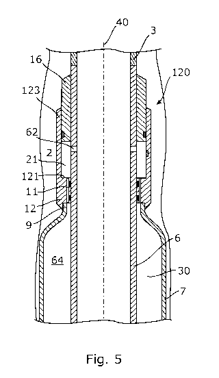
Fig. 5 shows an embodiment similar to what is shown in Figs. 2a and 2b, the
only
difference being that a first fluid passage 11 is provided in the connection
part
12. The first fluid passage 11 provides fluid communication between the
pressure
chamber 21 and the space 30 defined by the expandable sleeve. Hereby, the
hydraulic fluid for expanding the expandable sleeve is provided through the
pressure chamber 21. The first fluid passage 11 is for purposes of simplicity
only
shown in cross section, but it is to be regarded as one or a plurality of
first fluid
passages arranged in a substantially circular pattern in one or more
connection
parts 12 surrounding the tubular part. By arranging the first fluid passage 11
in
the connection part, the flow through the first fluid passage 11 may be
adjusted
to control the pressure inside the pressure chamber 21 and thus the force
induced on the connection part 12 and the first end of the expandable sleeve
7.
The flow through the first fluid passage may be controlled by varying the
cross-
sectional size of the first fluid passages or by providing flow regulating
means
known to those skilled in the art in the first fluid passage.
CA 02846794 2014-02-26
WO 2013/037817 PCT/EP2012/067822
Referring to Fig. 6, an embodiment comprising a fluid bypass passage 63 is
shown. In its initial position, the connection part 12 blocks the fluid bypass
passage 63 until a certain pressure is built up inside the pressure chamber,
which
is sufficient to move the connection part 12 to the position shown in Fig. 6.
In
5 Fig. 6, the fluid bypass passage 63 provides fluid communication between
the
pressure chamber and the space defined by the expandable sleeve when the
connection part 12 has been displaced a certain distance away from the
stationary part 16. Hereby, the hydraulic fluid injected into the pressure
chamber
21 will bypass the connection part 12, and the force induced by the hydraulic
10 fluid on the face 121 of the connection part will be reduced, and the
displacement
of the connection part will stop. Also, a physical stop (not shown) may be
provided on the outer face of the tubular part to restrict further
displacement of
the connection part if the first end of the expandable sleeve should only be
displaced a certain distance towards the opposite end. As would be understood
15 by those skilled in the art, a physical stop may be constructed in a
number of
different ways without departing from the scope of the invention.
Fig. 7 shows an annular barrier comprising a hydraulic pump 152 fluidly
connected with the inside of the tubular part and comprising control
electronics
153 for controlling the operation of the hydraulic pump. The hydraulic pump
and
the control electronics constitute the actuation mechanism, and upon
activation,
the hydraulic pump draws fluid from the inside of the tubular part via an
opening
154 and pumps the fluid into the pressure chamber 21 via an inlet 155. Hereby,
the connection part 12 is displaced by the hydraulic fluid to push the first
end of
the expandable sleeve 7 in the longitudinal direction towards the other end of
the
expandable sleeve 7 (shown in Fig. la). The control electronics may control
the
hydraulic pump 152 in a manner similar to the control of the hydraulic pump 52
described above.
Referring to Fig. 8, a connection unit comprising a pressure-intensifying
means in
the form of a hydraulic pressure intensifier 70 is shown. By the annular
barrier
comprising a hydraulic pressure intensifier 70, pressurised fluid inside the
tubular
part can be used to provide a pressurised fluid inside the pressure chamber 21
having a pressure substantially higher than the pressure of the fluid inside
the
tubular part. Hereby, the expansion pressure of the hydraulic fluid injected
inside
the tubular part may be substantially reduced for the benefit of other well
CA 02846794 2014-02-26
WO 2013/037817 PCT/EP2012/067822
16
hardware components deployed in the well. The hydraulic pressure intensifier
is
in fluid communication with the inside of the tubular part, as shown in Fig.
11.
Fig. 11 shows a diagram of an embodiment of a hydraulic pressure intensifier.
The hydraulic pressure intensifier 70 comprises a piston 74 being slidably
arranged within a piston housing 75. The piston has a first end face 741 and a
second end face 742, and the first end face 741 has a surface area Al larger
than
a second end surface area A2 of the second end face 742. Hereby, the piston 74
is capable of intensifying the pressure applied to the first end face 741 to a
higher pressure applied by the second end face 742 on the fluid inside a
second
space 75b of the piston housing 75. Further, the hydraulic pressure
intensifier
comprises a pilot control valve 76 for controlling fluid communication between
a
first space 75a, an inlet 72a of the pressure intensifier and an excess fluid
outlet
72b, providing fluid communication from the pressure intensifier to the
borehole
when the piston is retracted for letting a new amount of fluid into a second
space
75b. The pilot control valve has two positions. The first position allows
fluid
communication between the first space 75a and the inlet 72a for providing
fluid
in the first space 75a during pressurisation. The second position allows fluid
communication between the first space 75a and the excess fluid outlet 72b
during retraction of the piston.
The pilot control valve may automatically be switched between said first
position
and second position by a pilot 761 when the piston reaches its extreme
positions
in either end of the piston housing. Furthermore, the pressure-intensifying
means
may comprise a first one-way check valve 77 and a second one-way check valve
78. The first one-way check valve 77 allows fluid to flow from the inlet 72a
into
the second space 75b, but prevents the pressure-intensified fluid exiting the
second space 75b from flowing back towards the inlet 72a. In this way, the
high
pressure side of the pressure intensifier may be fed with fluid from the inlet
during retraction of the piston. The second one-way check valve 78 allows
pressure-intensified fluid to flow from the second space 75b towards an outlet
72c of the pressure intensifier and into the pressure chamber 21, but prevents
the fluid inside the pressure chamber 21 from flowing back towards the second
space 75b during retraction of the piston, where the second space 75b is
filled
with lower pressure fluid.
CA 02846794 2014-02-26
WO 2013/037817 PCT/EP2012/067822
17
In order to prevent fluids containing dirty particles from entering the
pressure
intensifier through the excess fluid outlet 72b, typically a filter 73 will be
arranged in the excess fluid outlet. During normal operation of the pressure
intensifier, fluid will only exit the excess fluid connection into the
borehole, but
under special circumstances, such as high pressure fluctuations in the
borehole,
the filter may be expedient.
It is to be understood by those skilled in the art that many different designs
and
variations of a hydraulic pressure intensifier may be implemented in the
annular
barrier, and such designs and variations are considered to be within the scope
of
the present invention.
Fig. 9 shows an annular barrier wherein a pressure vessel 80 is comprised in
the
actuation mechanism 20. The pressure vessel 80 is arranged in the stationary
part 16 of the connection unit 120 and contains a compressed propellant
adapted
to push the connection part 12 in the longitudinal direction by providing an
excess pressure in the pressure chamber 21. The propellant is supplied to the
pressure chamber 21 via the inlet 155 upon activation of the pressure vessel
80.
The pressure vessel 80 is activated when the pressure in the tubular part 6
has
exceeded a certain threshold value, indicating that hydraulic fluid is being
injected into the well to expand the expandable sleeve 7. Activation of the
pressure vessel 80 may be controlled in a number of different ways understood
by those skilled in the art. In one embodiment, a shear pin 125 or contact is
provided to register when the expandable sleeve is expanded by the fluid
pressure and the connection part 12 is under the influence of a pulling force
from
the expandable sleeve. When this occurs, the propellant inside the pressure
vessel is released to boost the longitudinal movement of the connection part
and
the first end of the expandable sleeve. Alternatively, the pressure vessel 80
may
be activated upon receiving a signal from a sensing mechanism, such as
described in the foregoing embodiments.
Fig. 10 shows a connection unit 120 comprising a connection part 112 slidably
connected with the tubular part 6. The stationary part 16 comprises a tubular
skirt 163 protruding from an end of the connection part 12, encircling the
tubular
part 6. The skirt and the tubular part define a housing wherein the connection
part 112 may slide in the longitudinal direction. The tubular part 6, the
stationary
part 16 and the connection part 112 together define the pressure chamber 21
CA 02846794 2014-02-26
WO 2013/037817 PCT/EP2012/067822
18
being fluidly connected to the inside of the tubular part 6 via the second
fluid
passage 62. When hydraulic fluid is injected into the pressure chamber 21, the
connection part 112 and the first end 9 of the expandable sleeve 7 connected
to
the connection part 112 slide in the housing in the longitudinal direction.
Any of the various embodiments of an annular barrier described above may
comprise one or more shear pins 125, as the one shown in Figs. 4a and 9. The
shear pin 125 restricts unintended displacement of the connection part and the
first end 9 of the expandable sleeve 7. When the annular barrier is inserted
into
the well, unintentional expansion of the expandable sleeve should for example
be
avoided in order to prevent the annular barrier from getting stuck in the
well. The
shear pin is only shown as an exemplary embodiment, and those skilled in the
art
would know that many other configurations of a shear pin may be provided
without departing from the scope of the invention.
Referring to Fig. 13, a well system 100 comprising the well tubular structure
3
and the annular barrier 1 is shown. The tubular part 6 of the annular barrier
1 is
connected with other casing sections to constitute the well tubular structure
3,
and when positioned in the well, the annular barrier 1 is expanded, as shown
in
Fig. 13. Hereby, a section 22 of the annulus surrounding the tubular structure
3
is isolated from the remainder of the annulus 2. A first zone 221 of the
borehole
is thus isolated from a second zone 222 of the borehole, as shown in Fig. 13.
The present invention is susceptible to embodiments of different forms.
Specific
embodiments are described in detail and are shown in the drawings, with the
understanding that the present disclosure is to be considered an
exemplification
of the principles of the invention, and is not intended to limit the invention
to that
illustrated and described herein. It is to be fully recognised that the
different
teachings of the different embodiments discussed above may be employed
separately or in any suitable combination to produce desired results.
An annular barrier may also be called a packer or similar expandable means.
The
well tubular structure can be the production tubing or casing or a similar
kind of
tubing downhole in a well or a borehole. As mentioned earlier, the annular
barrier
can be used both in between the inner production tubing and an outer tubing in
the borehole or between a tubing and the inner wall of the borehole. A well
may
CA 02846794 2014-02-26
WO 2013/037817 PCT/EP2012/067822
19
have several kinds of tubing and the annular barrier of the present invention
can
be mounted for use in all of them.
The valves that may be utilised to control the flow through the first and
second
fluid passages may be any kind of valve capable of controlling flow, such as a
ball
valve, butterfly valve, choke valve, check valve or non-return valve,
diaphragm
valve, expansion valve, gate valve, globe valve, knife valve, needle valve,
piston
valve, pinch valve or plug valve.
The expandable tubular metal sleeve may be a cold-drawn or hot-drawn tubular
structu re.
The fluid used for expanding the expandable sleeve may be any kind of well
fluid
present in the borehole surrounding the tool and/or the well tubular structure
3.
Also, the fluid may be cement, gas, water, polymers, or a two-component
compound, such as powder or particles mixing or reacting with a binding or
hardening agent. Part of the fluid, such as the hardening agent, may be
present
in the cavity between the tubular part and the expandable sleeve before
injecting
a subsequent fluid into the cavity.
By fluid or well fluid is meant any kind of fluid that may be present in oil
or gas
wells downhole, such as natural gas, oil, oil mud, crude oil, water, etc. By
gas is
meant any kind of gas composition present in a well, completion, or open hole,
and by oil is meant any kind of oil composition, such as crude oil, an oil-
containing fluid, etc. Gas, oil, and water fluids may thus all comprise other
elements or substances than gas, oil, and/or water, respectively.
By a casing is meant any kind of pipe, tubing, tubular, liner, string etc.
used
downhole in relation to oil or natural gas production.
In the event that the tools are not submergible all the way into the casing, a
downhole tractor can be used to push the tools all the way into position in
the
well. A downhole tractor is any kind of driving tool capable of pushing or
pulling
tools in a well downhole, such as a Well Tractor .
Although the invention has been described in the above in connection with
preferred embodiments of the invention, it will be evident for a person
skilled in
CA 02846794 2014-02-26
WO 2013/037817 PCT/EP2012/067822
the art that several modifications are conceivable without departing from the
invention as defined by the following claims.