Note: Descriptions are shown in the official language in which they were submitted.
CA 02846868 2014-02-26
WO 2013/033512
PCT[US2012/053305
PROCESS FOR PRODUCING TUBULAR CERAMIC STRUCTURES OF
NON-CIRCULAR CROSS SECTION
BACKGROUND OF THE INVENTION
[0001] This invention relates to a process for producing tubular ceramic
structures of non-circular cross section, to patterned arrays of such
structures, in
particular, of non-circular tubular anode-supported solid oxide fuel cell
(SOFC) units,
and to SOFC devices incorporating patterned arrays of non-circular tubular
SOFC
units.
[0002] Tubular ceramic structures are known for use as heat exchangers
where corrosive liquids or gases are encountered, recuperators, catalyst
bodies, as
components of fuel cells devices, particularly SOFC devices, and in a variety
of other
applications.
[0003] Tubular ceramic structures can be produced in a broad range of
lengths, wall thicknesses and cross-sectional areas and geometries employing
any of
several known and conventional techniques such as extrusion and dip coating.
Each
of these techniques for producing tubular ceramic structures generally, and
tubular
components of SOFCs in particular, is subject to certain inherent drawbacks
and/or
limitations.
[0004] In the case of extrusion, due to the need for the tubular
extrudate to
remain intact as it emerges from the extruder orifice, the ratio of the
diameter of the
tube to its wall thickness is typically low, e.g., under 15 and commonly under
10.
This practical requirement tends to limit the usefulness of extrusion methods
to the
production of relatively thick-walled tubular ceramic structures. While
relatively
thick-walled tubular anodes can be advantageous for the construction of some
types
of SOFC devices, in particular, those intended for high power output (e.g., 20
KW
and above), relatively thin-walled tubular anodes are generally preferred for
the
construction of SOFC devices of lower power output where their low thermal
mass
favors quicker start-ups and/or frequent on-off cycling.
[0005] The requirement for a relatively thick-walled extnidate, which can
only be achieved with an extrudable material of fairly high viscosity, e.g.,
one of
- 1 -
CA 02846868 2014-02-26
WO 2013/033512
PCT/US2012/053305
paste- or putty-like consistency, imposes yet another limitation on the
usefulness of
extrusion methods for the manufacture of tubular ceramic structures, namely,
the
need to carefully and completely dry the extrudate before subjecting it to
such high
temperature downstream processes as the burning out of organics (i.e.,
residual
solvent(s), dispersant(s), binder(s), etc.) and sintering. The drying of the
extrudate
requires suitable control over such operational parameters as temperature,
humidity
and time. Too rapid drying and/or insufficient drying can result in the
production of
mechanical defects in the extrudate before and/or after carrying out either or
both of
the aforementioned high temperature post-extrusion processes.
[0006] Still another limitation of the extrusion technique is its
inability to
readily vary the composition of the extruded tube, e.g., to alter the
composition of the
tube in one preselected location but not in another.
[0007] In the case of dip coating, the requirement that the ceramic-
forming
composition be applied to a tubular substrate generally limits this technique
to the
production of structures in which the substrate becomes an integral,
functional
component of the final article. This requirement for a tubular substrate
necessarily
restricts the type as well as the design of those devices that can utilize a
tubular
ceramic article produced by the dip coating technique. Moreover, it is
difficult in
practice to provide tubular ceramic structures with relatively thin walls
and/or with
walls of uniform thickness employing dip coating.
100081 There exists a need for a process for producing tubular ceramic
structures that is not subject to any of the aforedescribed drawbacks and
limitations of
known and conventional extrusion and dip coating techniques. More
particularly,
there is a need for a process which with equal facility is capable of
producing tubular
ceramic structures over a broad range of wall thicknesses, i.e., from the very
thin to
the very thick, does not require close attention to and control of the
conditions of
drying, is readily capable of altering or modifying the composition of the
tubular
product for a defined portion thereof and does not require the use of a
tubular
substrate which is destined to become a permanent component of the product.
- 2 -
CA 02846868 2014-02-26
WO 2013/033512
PCT/US2012/053305
SUMMARY OF THE INVENTION
[0009] In accordance with the present invention, a process for producing
tubular ceramic structures of non-circular cross section is provided which
comprises:
a) rotating a mandrel-spindle assembly having a non-circular external
cross section corresponding to the non-circular internal cross section of the
tubular
ceramic structure to be produced, the mandrel-spindle assembly comprising a
mandrel component and a spindle component, the mandrel component being a heat
shrinkable polymeric tube of non-circular cross section the external surface
of which
corresponds to the internal surface of the tubular ceramic structure of non-
circular
cross section to be produced and the internal surface of which defines a bore,
the
spindle component having a non-circular cross section corresponding to that of
the
bore of the mandrel and being in close fitting but slidably removable contact
therewith;
b) applying a ceramic-forming composition to the external surface of the
mandrel component of the rotating mandrel-spindle assembly to produce a
tubular
ceramic structure of non-circular cross section the internal surface of which
is in
contact with the external surface of the mandrel;
c) removing the spindle from the bore of the mandrel to provide a
mandrel-tubular ceramic structure assembly in which the interior surface of
the
tubular ceramic structure of non-circular cross section remains in contact
with the
external surface of the mandrel; and,
d) heat shrinking the mandrel component of the mandrel-tubular ceramic
structure assembly to cause the mandrel to undergo shrinkage to a reduced size
in
which the external surface of the mandrel separates from the interior surface
of the
tubular ceramic structure of non-circular cross section facilitating removal
of the
mandrel therefrom.
[0010] A major advantage and benefit of the foregoing process for
producing
a tubular ceramic structure of non-circular cross section lies in its ability
to provide
ceramic or cermet bodies over a wide range of ratios of length to external
diameter
and ratios of external diameter to wall thickness while meeting very precise
predetermined dimensional tolerances.
- 3 -
CA 02846868 2014-02-26
WO 2013/033512
PCT/US2012/053305
100111 Another advantage of the process herein for producing a tubular
ceramic structure of non-circular cross section is its capability for readily
and
conveniently varying, or modifying, the ceramic-forming composition along the
length of the structure. Ceramic-forming formulations of differing composition
can
be readily applied in a controlled manner to the external surface of the
rotating
mandrel at different rates and/or at different times during the production
process. The
degree of separation or blending of different ceramic-forming formulations
during the
production process can also be carefully controlled employing calibrated
dispensing
equipment known in the art to provide tubular ceramic products of non-circular
cross
section with enhanced performance capabilities compared with tubular products
made
by other fabrication techniques such as extrusion and dip coating.
[0012] The process of the invention can also utilize quick-drying ceramic-
forming compositions thus dispensing with the need for a carefully conducted
and
monitored drying operation.
[0013] And, since the heat-shrinkable tubular mandrel upon which the
tubular
ceramic structure is first formed when carrying out the process of this
invention is
eventually separated from the tubular product, there is no requirement that
the latter
be permanently united to a tubular substrate as is the case with dip coating.
BRIEF DESCRIPTION OF THE DRAWINGS
[0014] In the accompanying drawings in which like reference numerals
refer
to like elements:
[0015] Fig. IA is an isometric view of a tubular SOFC unit of generally
triangular cross section with portions partially cut away to better illustrate
its anode,
electrolyte and cathode components, the triangularly shaped anode component
being
advantageously produced in accordance with the process of the invention;
100161 Fig. 1B is a cross sectional view of the tubular SOFC unit of Fig.
lA
taken through a line perpendicular to the longitudinal axis of the latter;
[0017] Figs. 2A and 2B illustrate patterned arrays of individual tubular
SOFC
units of Fig. 1 for incorporation in an SOFC device;
- 4 -
CA 02846868 2014-02-26
WO 2013/033512
PCT/US2012/053305
[0018] Figs. 3A-3C illustrate other non-circular cross-sectional
geometries of
tubular anodes that can be produced in accordance with the process of the
invention;
[0019] Figs. 4A - 4C illustrate the formation of a mandrel-spindle
assembly of
generally triangular cross section for use in the process of the invention;
[0020] Figs. 5A and 5B illustrate the application of an anode-forming
composition to the rotating triangularly shaped mandrel-spindle assembly of
Fig. 4C
employing an ultrasonic spraying operation to produce the triangularly shaped
tubular
anode component of the SOFC unit of Fig. 1;
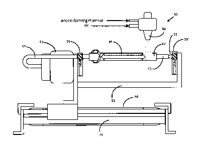
[0021] Fig. 6 is a logic flow diagram for one embodiment of computerized
control of the ultrasonic spraying operation shown in Figs. 5A and 5B;
[0022] Figs. 7A and 7B illustrate, respectively, the heating of the
mandrel-
tubular anode assembly to shrink the mandrel to its second further reduced
size
whereby the external surface of the mandrel separates from the interior
surface of the
triangularly shaped anode; and,
[0023] Figs. 8A and 88 illustrate, respectively, perspective and plan
views of
an SOFC device incorporating the patterned array of tubular SOFC units of Fig.
2B.
DETAILED DESCRIPTION OF THE INVENTION
[0024] It is to be understood that the invention herein is not limited to
the
particular procedures, materials and modifications described and as such may
vary. It
is also to be understood that the terminology used is for purposes of
describing
particular embodiments only and is not intended to limit the scope of the
present
invention which will be limited only by the appended claims.
[0025] In the specification and claims herein, the following terms and
expressions are to be understood as indicated.
[0026] The singular forms "a," "an," and "the" include the plural.
100271 All methods described herein may be performed in any suitable
order
unless otherwise indicated herein or otherwise clearly contradicted by
context. The
use of any and all examples, or exemplary language provided herein, e.g.,
"such as",
is intended merely to better illuminate the invention and does not pose a
limitation on
the scope of the invention unless otherwise claimed. No language in the
specification
- 5 -
CA 02846868 2014-02-26
WO 2013/033512
PCT[US2012/053305
should be construed as indicating any non-claimed element as essential to the
practice
of the invention.
[0028] As used herein, "comprising," including," "containing,"
"characterized
by", and grammatical equivalents thereof are inclusive or open-ended terms
that do
not exclude additional, unrecited elements or method steps, but will also be
understood to include the more restrictive terms "consisting of and
"consisting
essentially of."
[0029] Other than in the working examples or where otherwise indicated,
all
numbers expressing amounts of materials, reaction conditions, time durations,
quantified properties of materials, and so forth, stated in the specification
and claims
are to be understood as being modified in all instances by the term "about."
[0030] It will be understood that any numerical range recited herein
includes
all sub-ranges within that range and any combination of the various endpoints
of such
ranges or sub-ranges.
[0031] It will be further understood that any compound, material or
substance
which is expressly or implicitly disclosed in the specification and/or recited
in a claim
as belonging to a group of structurally, compositionally and/or functionally
related
compounds, materials or substances includes individual representatives of the
group
and all combinations thereof.
[0032] The expressions "heat shrinkable polymer" and "shape-memory
polymer" as used herein shall be understood as mutually inclusive.
[0033] The expression "ceramic-forming composition" shall be understood
to
include "cermet-forming composition."
[0034] The expression "external surface of the mandrel component" shall
be
understood to include the initially bare, or uncoated, external surface of the
mandrel,
i.e., the external surface of the mandrel prior to the application of some
other material
thereto, and the external surface of any material that has accumulated upon
the
external surface of the mandrel during its deposition thereon.
[0035] The expression "tubular ceramic structure of non-circular cross
section'' shall be understood to include all shape-sustaining tubular ceramic
structures
of non-circular cross section whether in an intermediate or final stage of
production,
- 6 -
e.g., as including tubular ceramic structures in the green state, i.e., those
containing
organic matter such as dispersant, binder, etc., where present in the ceramic-
forming
composition from which the structures are formed, and the organic matter-free
tubular
ceramic structures resulting from the burning out of such matter or from a
sintering
operation.
[0036]
[0037] Tubular ceramic structures of non-circular cross section in
general, and
tubular anode-supported SOFCs of non-circular cross section in particular, may
hold
one or more advantages over tubular structures of circular cross section and
comparable cross sectional area for certain kinds of applications. In the
particular
case of microtubular-type SOFC devices, the use of microtubular SOFC units of
non-
circular cross sectional geometry, e.g., that of a polygon and especially a
regular
polygon such as an equilateral triangle, square, equilateral pentagon,
equilateral
hexagon, etc., can permit a higher packing density, i.e., can allow for a
patterned
array containing a greater number of tubular SOFC units than that possible for
an
array of tubular SOFCs of circular cross section but comparable unit cross
sectional
area. This capability for higher packing density offers the potential for
greater power
output per unit volume of an SOFC device. In addition, the higher packing
density
that is achievable with tubular SOFC units of non-circular cross section
compared
with those of circular cross section may result in improved thermal stability
and
control of the SOFC device in which they are incorporated.
10038] In addition to the foregoing advantages, such patterned arrays
of
tubular SOFC units of non-circular cross section may make it possible to
maintain a
smoother, less turbulent flow of oxidizing gas, e.g., air, to the cathodic
surfaces and,
as a result, reduced back pressure with accompanying lower energy demand on
the
gas flow management unit, e.g., a blower system.
10039] Referring now to the figures, Fig. IA is a perspective
partially cut
away view of tubular anode-supported SOFC unit 10 of generally triangular
cross
- 7 -
CA 2846868 2019-01-31
CA 02846868 2014-02-26
WO 2013/033512
PCT/US2012/053305
section (shown in cross section through line A-A in Fig. 13) possessing an
interior
cermet-based, pore-containing anode component (i.e., fuel electrode) 11, the
interior
surface of which defines a bore, or passageway, 14, intermediate electrolyte
component 12 and cathode component 13.
100401 Figs. 2A and 2B illustrate two of the many different patterns in
which
bundles, or arrays, of individual triangularly shaped anode units 10 of Fig.
IA
(viewed in cross section as shown in Fig. 1B) may be arranged in an SOFC
device.
In Fig. 2A, the generally hexagonal array 20A of triangularly shaped tubular
SOFC
units 10 of Fig. lA possesses a longitudinal passageway 21 for guiding the
movement
of air, initially directed toward the array at one end thereof, in a direction
which is
substantially parallel to its longitudinal axis, through the array and
radially outwardly
therefrom. In Fig. 2B, the generally rectangular array 20B of triangularly
shaped
tubular SOFC units 10 of Fig. 1 possesses a central lateral passageway 22 for
guiding
the movement of air, initially directed toward the length of the array in a
direction
which is substantially perpendicular to its longitudinal axis, through the
array and
radially outwardly therefrom. Such an arrangement is illustrated in the SOFC
device
of Figs. 8A and 8B.
[0041] While the process of the invention is generally applicable to the
production of all tubular ceramic structures of non-circular cross section,
e.g., convex
and non-convex polygonal cross sections, it will now be specifically
illustrated for the
production of triangularly shaped tubular anode component 11 of tubular SOFC
unit
shown in Fig. 1.
100421 Triangularly shaped tubular anode component 11 is produced from an
anode-forming composition containing metal and ceramic compounds in
particulate
form. A slurry-forming amount of solvent or mixture of solvents such as water,
organic solvent such as methanol, ethanol, propanol, 2-butoxyethanol, acetone,
dimethylketone, methylethylketone, etc., or aqueous solution of one or more
organic
solvents such as any of the foregoing is used to provide a slurry of the
particulates.
Water is generally preferred for this purpose due to its negligible cost and
its
avoidance of environmental concerns such as flammability and toxicity which
are
generally associated with the use of volatile organic solvents.
- 8 -
CA 02846868 2014-02-26
WO 2013/033512
PCT/US2012/053305
[0043] The particulates may be maintained in suspension within the slurry
with the aid of a dispersant, or suspending agent, of which many kinds are
known in
the art, e.g., polymer electrolytes such as polyacrylic acid and ammonium
polyacrylate; organic acids such a citric acid and tartaric acid; copolymers
of
isobutylene and/or styrene with maleic anhydride, and ammonium salts and amine
salts thereof; copolymers of butadiene with maleic anhydride, and ammonium
salts
thereof; and, phthalate esters such as dibutyl phthalate and dioctyl phthalate
and
mixtures of these and other dispersants.
[0044] An organic binder is incorporated in the anode-forming composition
in
order to solidify, or set-up, the anode-forming composition into a shape-
sustaining
mass as it is applied to the external surface of the rotating mandrel during
the
spraying operation shown in Figs. 5A and 5B. The organic binder may be one
that
undergoes gelling by a physical mechanism, e.g., swelling in the presence of
water
and/or organic liquid, or by a chemical mechanism, e.g., crosslinking of
polymer
chains, or a combination of binders that individually undergo gelling, one by
a
physical mechanism, another by a chemical mechanism. Useful gelling binders
include such water-soluble and/or water-dispersible substances as
methylcellulose,
hydroxymethylcellulose, polyvinyl alcohol, polyvinyl acetate, polyvinyl
butyral,
polyhydroxyethylmethacrylate, polyvinylpyrrolidone (also capable of
functioning as a
dispersant), polysaccharides such as starch, modified starch, alginate, gum
arabic,
agar-agar, and the like. Useful binders of the cross-linkable polymer variety
include
polyacrylamides, polyacrylates, polymethylmethacrylates, and the like,
crosslinked in
situ employing known and conventional initiators such as peroxides,
persulfates, etc.
[0045] One or more known or conventional additives such as plasticizers,
e.g.,
polyethylene glycol, surfactants, foaming agents, defoaming agents, wetting
agents,
and the like, in art-recognized amounts can also be used to ensure a well-
dispersed,
homogeneous and eventually self-supporting composition (see R. J. Pugh et al.,
"Surface and Colloid Chemistry in Advanced Ceramics Processing", Marcel
Dekker,
October 1993). The physical characteristics of these anode-forming
compositions
such as their viscosity and the time required for their transition from a
fluid state to a
- 9 -
CA 02846868 2014-02-26
WO 2013/033512
PCT/US2012/053305
shape-sustaining state can be controlled through selection of the components
of the
compositions and/or their amounts.
[0046] The ceramic material incorporated in anode component 11 (and in
electrolyte component 13) can be stabilized-zirconia, preferably utilized for
high
operating temperature SOFCs (700 C to 1000 C). This includes preferably 8
mol %
yttria-stabilized zirconia ("Y8SZ"), (Zr02)0.92(Y203)o.os. Another useful
material is
doped-ceria, preferably used for intermediate operating temperature SOFCs (500
C
to 700 C). This includes preferably gadolinium-doped ceria ("CGO"),
(Ce0.90Gdo.10)01.95. However, each of these materials may be employed over a
wide
range of temperatures. Of course, it is contemplated that other materials
suitable for
SOFC applications known in the art may be used.
[0047] The metal phase used in the anode and electrolyte components
belongs, preferably, to the transition group of metals of the periodic table
of elements,
their alloys or physical mixtures. Nickel (Ni) is preferred, because of its
high
electrical conductivity under reducing atmosphere and its cost effectiveness.
Metal
may be introduced in the supported fuel electrode and cermet electrolyte via
different
precursors, known to those skilled in the art such as metal powders, metal
oxide
powders, and metal salts (aqueous or non-aqueous). Metal oxide powders, such
as
green NiO, are often preferred because of their cost effectiveness and their
adaptability to ceramic processing. The use of fine metal oxide powders is
particularly recommended for the cermet electrolyte processing since the metal
will
remain oxidized under SOFC operating conditions.
[0048] The metal phase range may vary from 30 vol % to 80 vol % in the
cermet anode. The thickness in the sintered state of the cermet anode will
depend on
the overall design of the fuel cell. For example, anode thickness in small
diameter
tubular fuel cells can range from 0.2 mm to 1.0 mm.
100491 The metal phase range can vary from 0.1 vol % to 15 vol % in the
cermet electrolyte. The thickness of the cermet electrolyte in the sintered
state is
preferably below 500 microns and most preferably is between 5-30 microns. The
specific thickness chosen will often be determined by the size and design of
the fuel
cell as well as other factors apparent to those skilled in the art.
-10-
CA 02846868 2014-02-26
WO 2013/033512 PCT/US2012/053305
[0050] The viscosity of a ceramic -forming composition can vary within
fairly
wide limits, e.g., from 1 to 500,000 cP at 20 C. For the ultrasonic spraying
operation
for making a tubular anode structure described, infra, in connection with
Figs. 5A and
5B, the viscosity of the anode-forming composition can range, e.g., from 1 to
100 cP
at 20 C, and preferably from 5 to 20 cP at 20 C.
[0051] The use of a relatively thick-walled anode support, e.g., one
having a
wall thickness of from 0.9 to 5.0 mm with a diameter up to 500 mm, can allow
the
use of relatively thin subsequently formed electrolyte and/or cathode
components,
e.g., an electrolyte layer having a thickness of from 0.005 to 0.500 nun
and/or a
cathode layer having a thickness of from 0.010 to 1 mm. A reduced thickness
for the
electrolyte and/or cathode components can provide improved thermal shock
resistance and electrochemical performance. Such improved mechanical stability
and
fuel cell performance may also enable the fuel cell to operate at a lower
temperature.
This in turn can allow the use of more cost-effective materials (e.g.,
stainless steel)
within the fuel cell stack (e.g., for cell manifolding). =
[0052] The use of relatively thin-walled anode support, e.g., one having
a wall
thickness of from 0.020 to 2 mm with a diameter up to 30 mm, can be
advantageous
for use, an noted above, in the construction of lower power output SOFC
devices
(e.g., below 20 KW and more commonly below 5 KW) where their lower thermal
mass tends to better accommodate quicker start-ups and/or frequent on-off
cycling.
[0053] The process of this invention also allows for the optional
deposition of
a thin interlayer between the anode and/or cathode component(s) of the SOFC
and its
electrolyte component. It can be advantageous to provide an optional
interlayer thin
film between anode 11 and electrolyte 12, between electrolyte 12 and cathode
13, or
between electrolyte 12 and both anode 11 and cathode 13 as interlayer thin
films can
be made to increase fuel cell performance, e.g., through the use of catalytic
materials,
and/or prevent or inhibit adverse chemical reactions during sintering. An
interlayer
thin film can include one or more catalytically active materials such as doped
cerium
and gadolinium oxide (COO), as previously disclosed, in a range of from 40 to
60 vol
%, with the balance being Ni and Ru. Other catalytically active materials
include
scandium-stabilized zirconia (SSZ), again with the balance being Ni and Ru. An
-11-
CA 02846868 2014-02-26
WO 2013/033512
PCT[US2012/053305
interlayer thin film can contain still other catalytically active components
such as Pt,
Pd and Rh to name but a few.
[0054] Referring to the drawings illustrating the production, in
accordance
with the process of the invention, of a tubular ceramic structure of non-
circular cross
section as exemplified by tubular anode component 11 of triangular tubular
SOFC
unit 10 of Fig. I, the forming of mandrel-spindle assembly 45 of Fig. 4C is
illustrated
in Figs. 4A and 4B.
[0055] As indicated above, the mandrel-spindle assembly of non-circular
cross section that is employed in the process of the invention includes a
mandrel
component and a spindle component, the mandrel component being fabricated from
a
heat-shrinkable polymeric tube and having an external surface corresponding to
the
internal surface of the tubular ceramic structure to be produced and an
internal
surface defining a bore which is in close fitting but slidably removable
contact with
the external surface of the spindle component. Since the diameter of stock
sections of
heat shrinkable polymeric tubing seldom provide the requisite close fit,
slidably
removable contact, with the external surface of the spindle (whose external
cross
section and surface define the internal cross section and surface of the
tubular ceramic
structure, e.g., tubular anode, to be produced), it is often necessary to heat-
shrink
oversized stock tubing upon the spindle to provide the mandrel-spindle
assembly for
use in the production of a particular tubular ceramic structure in accordance
with the
process of the invention. One suitable procedure for providing the mandrel-
spindle
assembly employed in the process of the invention is illustrated to Figs. 4A-
4C.
[0056] As shown in Fig. 4A, mandrel-spindle subassembly 40 includes
oversized cylindrically shaped mandrel 41 possessing a bore 42 of sufficient
diameter
as to loosely accommodate triangularly shaped spindle 43 and its optional
closely
fitting, removable or non-removable, friction-reducing polymer cladding, or
covering
44. Mandrel 41 will generally possess a length corresponding to the length of
tubular
anode 41 but somewhat less than the full length of spindle 43.
[0057] Oversized mandrel 41 is fabricated from a heat shrinkable, or
shape-
memory, polymer numerous kinds of which are known in the art, e.g., those
described
in Lendlein et al., "Shape-Memory Polymers", Angew. Chem. Int. Ed. 2002, 41,
-12-
CA 02846868 2014-02-26
WO 2013/033512
PCT/US2012/053305
2034-2057 (W1LEY-VCH Verlag GmbH). Specific useful heat shrinkable polymers
include, e.g., polyethylene terephthalate (PET), block copolymers of PET and
polyethylene oxide (PET-PEO) and block copolymers of polystyrene and poly(1,4-
butadiene) to name but a few.
[0058] Triangularly shaped spindle 43 can be formed from any suitably
rigid
material, i.e., one that resists flexing or other deformation when undergoing
rotation,
such as metal, e.g., aluminum, steel ,bronze, etc., glass or other ceramic,
non-
reinforced or reinforced polymer, etc. Spindle 43 can be a solid structure as
shown, a
hollow structure such as a tube, a composite of different materials, e.g., a
solid or
hollow metal core whose exterior surface may optionally be clad with a
friction-
reducing polymer the function of which is to facilitate the removal of heat-
shrunk
mandrel 47 (shown in Fig. 4C) at a later point in the process of the
invention. In the
embodiment of triangular spindle 43 shown in Fig. 4A, the spindle is of solid
metal
construction, e.g., steel, clad with friction-reducing polymer layer 44.
Optional
cladding 44 can be fabricated from a friction-reducing polymer such as
polyfluorotetraethylene (PTFE). In place of polymeric cladding 44, spindle 43
can be
coated with a lubricious material. Suitable lubricious materials include
organic
lubricants such as liquid petroleum-based lubricants, natural and synthetic
waxes,
polyalphaolefins, and the like, and inorganic lubricants in particulate form
such as
boron nitride, graphite, molybdenum sulfide, and the like.
100591 Fig. 4B illustrates the first heat shrinking treatment whereby
expanded
mandrel 41 of mandrel-spindle subassembly 40 is made to undergo shrinkage to a
first reduced size providing close fitting, slidably removable mandrel 47 of
mandrel-
spindle assembly 45 illustrated in Fig. 4C. As shown in Fig. 4B, an array of
mandrel-
spindle subassemblies 40 are disposed between a pair of end plates 46, each
end plate
possessing an array of apertures 48 for receiving the cylindrical end portions
of
spindle 43 of each mandrel-spindle subassembly thereby supporting the
subassemblies, in this particular case, in a substantially horizontal
orientation. The
supported array of mandrel-spindle subassemblies is then subjected to heat
shrinking
treatment carried out under conditions of temperature and time sufficient to
cause
each expanded mandrel 41 to undergo shrinkage to a first reduced size in which
it
- 13 -
CA 02846868 2014-02-26
WO 2013/033512
PCT[US2012/053305
assumes a close but slidably removable fit with its triangularly shaped
spindle 43
thereby providing shrunken mandrel 47 of mandrel-spindle assembly 45 of Fig.
4C.
For mandrel 41 fabricated from polyethylene terephthalate polymer, this first
heat
shrinking treatment can advantageously be carried out by subjecting the
supported
array of mandrel-spindle subassemblies 40 to a temperature within the range of
from
105 to 180 C for an exposure time of from 5 to 45 minutes.
10060] As one alternative to the aforedescribed operation of heat
shrinking
oversized mandrel 41 directly onto triangularly shaped spindle 43, a length of
oversized heat shrinkable polymeric tubing of a length equal to several
lengths of
oversized mandrel 41 can be heat shrunk upon a rigid support, e.g., a
triangularly
shaped stainless steel rod, optionally possessing a friction-reducing cladding
or
lubricant such as any of those mentioned, and having an external cross
sectional
geometry identical to that of spindle 43. Following the heat shrinking of the
tubing to
where it closely fits the exterior surface of the rigid support, the latter is
removed, the
heat-shrunk tubing is cut to individual lengths providing several heat-shrunk
mandrels
47 and triangularly shaped spindle 43 is inserted in the bore of an individual
mandrel
47 to provide the mandrel-spindle assembly of triangular cross section of Fig.
4C.
100611 The selected anode-forming composition can be applied to the
external
surface of rotating mandrel-spindle assembly 45 employing any suitable means,
e.g.,
spraying which is generally preferred, roller or brush-coating employing a
doctor
blade for removal of excess slurry, and similar procedures.
100621 Figs. 5A and 5B illustrate a preferred spraying procedure for
applying
an anode-forming composition such as those described above to the external
surface
of mandrel component 47 of triangularly shaped mandrel-spindle assembly 45 of
Fig. 4C, namely, ultrasonic spraying, to provide anode component 11 of SOFC
unit
of Fig. 1. Mandrel-spindle assembly 45 is mounted within traveling support
frame
51 of ultrasonic spray apparatus 50 and securing held in place therein by
spring-
loaded spindle-locking member 52. Motor 53 rotates mandrel-spindle assembly 45
through flexible drive shaft 57 at adjustable rates, e.g., from 5 to 150
r.p.m., during
operation of overhead stationary ultrasonic spray nozzle 54 which receives
anode-
forming composition from a remote source (not shown) and an atomizing gas,
-14-
advantageously air. Feed pressures for both the anode-forming composition and
the
atomizing gas supplied to ultrasonic spay nozzle 54 and the distance between
the tip
of the spray nozzle and the external surface of mandrel 47 as with other
spraying
operational parameters can be adjusted to provide optimal spraying conditions
for a
particular anode-forming operation. In general, anode-forming composition and
atomizing gas can be fed to ultrasonic spray nozzle 54 at pressures sufficient
to
deposit from 0.3 to 30,000 mg/sec of the composition upon the external surface
of
mandrel 47 with the distance between the tip of the nozzle and the external
surface of
the mandrel being maintained at from 0.5 to 10.0 cm.
[0063] Traveling frame 51 is repeatedly driven in back-and-forth
cycles upon
horizontal support track 55 by drive belt 56 at adjustable rates, e.g., from
0.1 to 100.0
cm/sec, during the spraying operation for a number of cycles sufficient to
provide an
anode of predetermined wall thickness, e.g., from 0.25 to 5.0 mm. The number
of
cycles required for a particular tubular anode structure will depend largely
upon the
wall thickness desired, the length of the anode, the quantity of anode-forming
composition deposited upon the external surface of the rotating mandrel per
unit of
time and similar factors.
[0064] As shown in Fig. 5B, cam unit 59 at one end of drive shaft 57
and
companion cam unit 59' at the spindle locking end of travelling support frame
51 are
provided to maintain a substantially constant distance between the tip of
spray nozzle
54 and the surface of mandrel 47 as triangularly shaped mandrel-spindle
assembly 45
rotates. Each cam unit includes a retainer 60 for engagement with a
cylindrical end
portion of spindle 43 and tensioning springs 61 and 61' attached at one end to
the
housing of the cam unit and at the other to retainer 60. Tensioning springs 61
and 61'
maintain rotating mandrel-spindle assembly 45 under tension as mandrel surface
74
follows spring-tensioned cam roller 62 which is held fixed in place within
mount 63.
As rotating mandrel-spindle assembly 45 moves up and down by the camming
action
through the vertical distance indicated by the arrows, flexible drive shaft 57
moves up
and down in coordinate fashion by the same distance. By this simple camming
action, the surface of rotating mandrel 47 will maintain approximately the
same
distance from the tip of spray nozzle 54.
- 15 -
CA 2846868 2018-10-23
CA 02846868 2014-02-26
WO 2013/033512
PCT/US2012/053305
100651 It is, of course, within the scope of this invention to change or
modify
one or more aspects of the spraying apparatus of Figs. 5A and 5B, e.g., to
provide a
traveling (reciprocating) spray nozzle and a fixed support frame, to provide
two or
more spray nozzles capable of independent operation so as to alter the
composition of
the anode as it is being formed, to utilize a spray nozzle oriented in other
than the
overhead position shown, to provide 3-axis movement of the spray nozzle, etc.
[0066] Fig. 6 represents a logic flow diagram for one embodiment of a
computerized system of control of the spraying operation illustrated in Figs.
5A and
5B.
[0067] In the following operations for producing anode component 11 and
as
illustrated in Figs. 7A and 7B, after removing spindle 43 from the anode-
coated
mandrel-spindle assembly 45 resulting from the aforedescribed spraying
operation,
the spindle-free assembly, now designated mandrel-anode assembly 70 and
possessing bore 71, is mounted upon vertical ceramic pin 72, there being
sufficient
clearance between interior surface 73 of mandrel 47 and external surface 74 of
pin 72
to allow the mandrel when subjected to the second heat shrinking treatment to
undergo further shrinkage thereby pulling away from interior surface 75 of
tubular
anode unit 11. For production efficiency, an array of vertically mounted
mandrel-
anode assemblies 70 as shown in Fig. 7A is subject to the second heat treating
operation. As in the case of the first heat shrinking treatment shown in Fig.
4B, the
temperature and time conditions for effecting this further shrinkage of the
mandrel
will depend to a large extent on the heat shrinking characteristics of the
polymer from
which the mandrel is made.
[0068] In the particular case where mandrel 47 is formed from
polyethylene
terephthalate, suitable conditions for the second heat shrinking treatment
include a
temperature of from 120 to 350 C and an exposure time of from 1 to 100
minutes.
[0069] As a result of this second heat shrinking treatment, and as shown
in
Fig. 78, mandrel 47 undergoes another reduction in size, i.e., to the second
reduced
size of mandrel 76 in which external surface 77 thereof completely separates
from
interior wall 75 of tubular anode structure 11 allowing the anode to be
readily
separated from mandrel 76 without incident and thereafter subjected, if
desired, to
- 16 -
CA 02846868 2014-02-26
WO 2013/033512 PCT/US2012/053305
one or more further production operations such as the formation thereon of one
or
more additional layers, e.g., interlayer thin film(s), electrolyte, cathode,
etc., burning
out of organics, sintering, and so forth. It is also within the scope of the
invention to
form a tubular structure upon mandrel 47 which is equal in length to several
lengths
of tubular anode 11 and thereafter to subdivide the tubular structure into the
desired
lengths of tubular anode 11.
[0070] The process of the invention is generally applicable to the
production
of all manner of tubular ceramic structures of non-circular cross section
including,
without limitation, tubular anode components of a SOFC unit encompassing a
wide
range of lengths, outside diameters and wall thicknesses. For example, the
process
can be used to provide a tubular ceramic structure, e.g., a tubular anode,
possessing
one of the following sets of dimensions:
External
Set of Cross-Sectional Wall
Dimensions Length (mm) Area (mm2) Thickness (mm)
A 20 to 1000 1 to 50 0.100 to 5
50 to 500 2 to 30 0.200 to 3
100 to 250 5 to 20 0.25 to 2
[0071] In the perspective and plan views of tubular SOFC unit 80 shown,
respectively, in Figs. 8A and 88, blower system 81 provides a flow of gaseous
fuel,
e.g., hydrogen, to manifold 82 for introduction into and through passageway 14
of
each tubular SOFC unit 10 constituting an SOFC array 20B of Fig. 2B. Second
blower system 83 provides a flow of air, initially at ambient temperature, to
manifold
84 from which it exits through outlets 85 to provide a source of oxygen for
cathode
component 12 of each tubular SOFC unit 10 of an SOFC array 20B. The air
entering
manifold 84 gains heat from the hot combustion gases exiting tail burner 86
into heat
exchanger 87. The dotted lines show the flow path of the heated air exiting
outlets 85
of manifold 84, and into, through and radially outwardly from central lateral
passageway 22 of SOFC arrays 20B and into tail burner 86 where it provides
oxygen
to support combustion of unspent fuel present in the exhaust gas emerging from
the
- 17 -
= CA 02846868 2015-12-02
tubular SOFC elements into exhaust manifold 88 and from there into the tail
burner.
Finally, the hot combustion gases enter heat exchanger 87 where they serve to
preheat
incoming air provided by second blower system 83 as previously indicated.
Blower
systems 81 and 83, which are of similar construction, are described in detail
in
copending, commonly assigned U.S. patent application pub. no. 2012/0328969,
filed
June 24, 2011.
[0072] The following example is illustrative of the process of the
invention
for producing a triangularly shaped tubular anode support component of an SOFC
unit in the green state, i.e., the state in which the anode is self-supporting
but still
contains organic components such as residual solvent, dispersant, binder, etc.
EXAMPLE
[0073] A green state tubular anode having the cross section of an
equilateral
triangle with rounded vertices is produced possessing the following
dimensions:
length of 230 mm, cross-sectional area of about 31.5mm2 and wall thickness of
0.50 mm.
100741 An anode-forming composition in the form of an organic
solvent
slurry is provided by combining the following ingredients in the indicated
amounts:
Component Amount (g)
8-mol% yttrium zirconium oxide powder 2.10
NiO powder 3.90
methylethyllcetone (MEK) 10.0
polyvinylpyrrolidone (PVP) powder 2.00
[0075] The tubular anode is produced from the foregoing anode-
forming
composition employing the following operations.
[0076] (a) Forming the Triangularly Shaped Mandrel-Spindle
Assembly
Stock heat-shrinkable polyethylene terephthalate (PET) cylindrical
tubing having an outside diameter of 7.6 mm is divided into 230 mm lengths
with
each tubular section being weighed to within + 0.01g accuracy. A triangularly
shaped
spindle of 305 mm length clad with a friction-reducing layer of
polytetrafluoroethylene (PTFE) and possessing a cross sectional geometry
- 18 -
CA 02846868 2014-02-26
WO 2013/033512
PCT/US2012/053305
corresponding to the triangularly shaped bore of the tubular anode structure
to be
produced is inserted into the bore of a PET tubular section to provide a pre-
shrunk
oversized mandrel-spindle subassembly. The subassembly is heated in a
convection
oven to 110 C for 10 min. to shrink the PET tubular section (the oversized
mandrel
component of the subassembly) to the point where the mandrel becomes closely
fitted
to the spindle with the spindle being sidably removable therefrom. The thus-
formed
mandrel-spindle assembly is now ready for use in the spraying operation.
100771 (b) Spraying the Anode-Forming Composition Upon the
Surface of the Mandrel-Spindle Assembly to Form a
Triangularly Shaped Anode in the Green State
The triangularly shaped mandrel-spindle assembly is installed in the
traveling support frame of a FlexiCoat ultrasonic spray coating apparatus
(Sono-Tek
Corporation, Milton, New York). The mandrel-spindle assembly is rotated about
its
longitudinal axis at a rate of 125 r.p.m. during the spraying operation. The
surface of
the rotating mandrel is maintained at a constant distance from the tip of the
ultrasonic
spray nozzle by the camming modification of the apparatus described infra. The
ultrasonic spray nozzle delivers approximately 0.5 ml/sec of anode-forming
composition in a slightly bowed-shape spray pattern of microdroplets to the
surface of
the rotating mandrel. By the time the spray impinges on the surface of the
rotating
mandrel, sufficient evaporation of the volatile component of the anode-forming
composition, namely, its methylethylketone (MEK) slurry-forming component, has
taken place so that the sprayed material, now semi-dry, adheres to the mandrel
as a
substantially uniform coating or layer thereon. Continuous back-and-forth
(reciprocal) motion of the traveling support frame of the spraying apparatus
results in
the increasing accumulation of anode-forming composition on the surface of the
mandrel. After a predetermined period of time (or number of spraying cycles),
spraying is discontinued, the spindle is removed from the coated mandrel to
provide a
triangularly shaped mandrel-tubular anode assembly and the latter is weighed
to
within + 0.01g from which it is calculated that 5.6 g anode-forming
composition, now
substantially devoid of its volatile MEK component, has been deposited on the
mandrel as a tubular anode structure of generally triangular cross section
having the
dimensions indicated above.
- 19-
CA 02846868 2015-12-02
10078) (c) Heat-treating the Mandrel-Tubular Anode Assembly to
further Heat Shrink the Mandrel
The triangularly shaped mandrel-tubular anode assembly is vertically
supported upon a ceramic pin having a diameter that is smaller, e.g., 20-30%
smaller,
than the interior diameter of the mandrel. The supported mandrel is placed in
a
convection oven and heated to the target temperature of 250 C at a heating and
cooling rate of 1 C/min. and a dwell time at the target temperature of 60
minutes. As
a result of this heat treatment, the mandrel shrinks and separates from the
interior
surface of the tubular anode from which the triangularly shaped mandrel is now
readily removed.
100791 Although the invention has been described in detail for the purpose
of
illustration, it is understood that such detail is solely for that purpose,
and variations
can be made therein by those skilled in the art.
- 20-