Note: Descriptions are shown in the official language in which they were submitted.
CA 02847311 2014-03-21
EARTH BORING DEVICE AND METHOD OF USE
[FIELD OF THE INVENTION]
[0001] The present invention relates to an earth boring device and more
particularly, the
present invention relates to a method and apparatus for stabilizing a drill
string during earth
boring and expansion reaming.
[BACKGROUND OF THE INVENTION]
[0002] Drilling tools of all varieties are known in the art. One of the
problems that has
been pervasive in the solutions presented by the prior art relates to
dependability of the tool and
also expediency when resetting the reamer function once it has been deployed.
As has been
identified in the prior art, resetting the ball used to redirect the drilling
fluid can be arduous and
requires removal of the tool from within the formation partial disassembly and
subsequent
reassembly. All of these operations are time intensive and are therefore very
costly in a drilling
operation. The present invention seeks to mitigate the limitations with
existing arrangements to
provide a more effective drilling tool which may be easily and quickly reset
in the field in order
to keep things moving for maximum efficiency in a notoriously expensive
operation.
100031 Typical arrangements are used in drilling for oil and gas and may
include a
stabilizer and enlargement reamer. The stabilizer is used to prevent torsions
and other forces
from damaging or changing the direction of the string in use. The reamers are
useful to enlarge
the bore hole and are retractable within the body of the tool. Examples of
such tools have been
delineated in the prior art. An example of which is shown in United States
Patent Publication No.
US2012/0279784, the author which is Harvey et al. The technology relates to a
slide reamer and
stabilizer tool. The tool has reamer cartridges which can be removed and
replaced with stabilizer
cartridges having stabilizer inserts and hard faced stabilizer cones.
[0004] Turning to the expandable reamers, United States Patent No.
7,493,971, issued
February 24, 2009 to Nevlud et al. teaches a concentric expandable reamer.
This is one of the
earlier reaming arrangements which provides for movable arms deflectable
radially outward
from the reamer for borehole enlargement. A fairly complex mechanism is
disclosed in the
1
CA 02847311 2014-03-21
patent and there is no discussion regarding resetting or repositioning of the
movable arms in an
expeditious mariner.
[0005] Radford et al., in United States Patent No. 7,900,717, issued March
8, 2011,
further advances the expandable reamer technology. In this arrangement a push
sleeve is
disposed in the inner bore of the body and is coupled to each one of the
blades to effect axial
movement along a track to an extended position responsive to exposure to a
pressure or force of
drilling fluid in the flow path of the inner bore. Similar to the Nevlud et
al. document, this
document does not set forth any instruction regarding the reset of the blades.
[0006] Radford et al., further expands on the stabilizer with reamer
elements in United
States Patent No. 8,020,767, issued October 4, 2011. In this arrangement the
blades may include
at least one roller element for reaming a wellbore.
[0007] For the still, Radford et al. further delineates reamers in United
States Patent NO.
7,681,667, issued March 23, 2010.
[0008] Despite the panacea of developments in this area of technology,
there is a notable
absence of expandable reamers with a reset function that can be expeditiously
effected in the
field. The present invention addresses the absence of the reset feature to
present a more efficient
arrangement.
[SUMMARY OF THE INVENTION]
[0009] One object of the present invention is to provide improved earth
boring tool
which may be expeditiously reset in the field with minimum downtime.
[0010] A second object of the present invention according to one embodiment
is to
provide a method of resetting an earth boring tool having a tubular body
attached to a drill string,
a drill bit disposed on an end thereof, expandable reaming elements for
enlarging a bore hole, a
movable member movable by fluid pressure within said tool to effect movement
to a use position
of said reaming elements and an actuating member for actuating said movable
member,
2
CA 02847311 2014-03-21
comprising: providing a reset member; removing said drill bit to expose an
opening in said tool;
positioning said reset member within said opening of said tool; dislodging
said actuating
member from a seating within said tool; and resetting said blockage member to
an initial position
where said expandable reaming elements are retracted.
[0011] A further object of one embodiment of the present invention
is to provide an earth
boring tool, comprising: a tubular cutter housing having a plurality of
retractable cutting
elements retractably mounted within said housing; a piston housing connected
to said cutter
housing for housing a movable member coaxially mounted therein for axial
movement within
said cutter housing and said piston housing; a movable member disposed within
said tool and
movable from said cutter housing to said piston housing for redirecting fluid
flow into said cutter
housing to deploy said retractable cutting elements; an actuating member for
positioning within
said tool to actuate movement of said movable member to said piston housing;
and reset means
selectively positionable within said tool for retrieving said actuating member
and repositioning
said movable member from said piston housing to said cutter housing.
=
[BRIEF DESCRIPTION OF THE DRAWINGS]
100121 Figure 1 is a view of the tool according to one embodiment
of the present
invention;
[0013] Figure IA is a perspective enlarged view of the cutter
housing of the tool;
[0014] Figure 1B is a longitudinal cross-section of an isolated
section of the cutter
housing shown in Figure 1A;
[0015] Figure 2 is a longitudinal cross-section view of the tool;
[0016] Figure 3 is a longitudinal cross-section view of the tool
illustrating the actuating
member as it is position within the tool;
[0017] Figure 4 is a longitudinal cross-section view of the tool
illustrating the positioning
of the actuating member in a position where the cutting elements are primed
for deployment;
[0018] Figure 5 is a view similar to Figure 4 illustrating full
deployment of the cutting
elements and the positioning of the actuating member; and
[0019] Figure 6 is a view similar to Figure 5 illustrating the
disposition of the reset
member within the tool.
3
CA 02847311 2014-03-21
[0020] Similar numerals used in the Figures denote similar elements.
[DETAILED DESCRIPTION OF THE PREFERRED EMBODIMENTS]
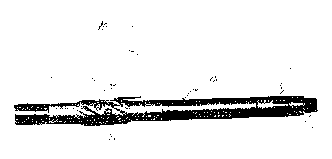
[0021] Referring now to the drawings and particularly Figure 1, numeral 10
generally
denotes one embodiment of the earth boring tool. The tool includes, as is
typical with these
arrangements, a first stabilizing member 12 referred to in the art as a sub
which is threadibly
connected to the cutter housing 14. Extending coaxially and in threaded
connection from the
cutter housing 14 is a piston housing 16. One end of the piston 16 has a
bottom sub 18, which
has a threaded segment 20 for typically receiving a drill bit head (not
shown).
[0022] Figures I A and 1B illustrate greater detail concerning the cutter
housing 14. As is
evident from Figure 1A, the cutter housing 14 provides a plurality of helical
flutes 16. The
helices are disposed at an angle of 27.6 as a first possibility. It will be
appreciated by those
skilled in the art that this is an example of the invention. Between the
flutes 16 are a plurality of
raised segments 18 each having a plurality of apertures 20 extending
therealong in equidistant
relation. Referring to Figure 1B, each of the apertures 20 retains a piston 22
to which is
connected a cutting element shown best in Figure 1. Each cutting element, in
this example,
includes a plurality of cutting buttons 24 which may be made of a sufficiently
durable material
such as tungsten carbide that is widely used for this purpose. As is evident
from Figure 1B and
equally true for the complete arrangement 10 a longitudinal shaft 26 extends
through the entire
cutter housing as well as all the elements connected thereto set forth
regarding the discussion of
Figure 1.
[0023] Turning now to Figure 2, shown as a longitudinal cross-section of
the tool 10 the
structural relationship of the individual members as discussed in Figure 1.
The tool 10 in Figure
2 is depicted in a state where the cutting elements 22 is a retracted state
within cutter housing 14.
In this embodiment, there is an elongate member 26 disposed coaxially within
cutter housing 14.
The elongate member 26 is hollow and allows for fluid flow therethrough so
that fluid can flow
from sub 12 to sub 18 as is known in the art. The typical fluid is drilling
mud well known to
those skilled. The elongate member 26 is mounted for slidable movement within
cutter housing
14 and extends substantially the full length of the housing 14. A terminal end
28 of member 26
4
CA 02847311 2014-03-21
provides a plurality of slots 30 the purpose of which will be discussed
hereinafter. There are slots
30 which define a series of individual fingers 32. Elongate member 26 is more
commonly
referred to as a collet sleeve in the art. The collet sleeve 26 at an opposed
end from fingers 32,
referenced by numeral 34 includes a substantially frustocomical Conoco end
portion, the purpose
of which will be discussed hereinafter. Collet sleeve 26 is movable within the
tool 10 as
mentioned herein and previously by making use of an actuating member 36 shown
in Figure 3.
The actuating member 36 comprises a sphere which is positionable within the
tool in a position
as noted in Figure 3.
[0024] The purpose of the actuating member or sphere 36 as it will be
referred to
hereinafter is to actuate movement of the collet sleeve 26 from the position
shown in Figure 3
within cutting housing 14 to the second position shown in Figure 4, where the
collet sleeve 26 is
disposed within piston housing 16. The mass of the sphere 36 is sufficient to
move the collet
sleeve 26 into the position within piston housing 16. Once the sphere 36 is
positioned as noted,
fluid flow and particularly drilling mud flow is altered within the tool such
that the fluid builds
within cutter housing 14 to actuate the pistons 22 in order to urge the cutter
elements 24
outwardly as shown in Figure 5 to a position where the cutter elements 24
extend outwardly from
the cutter housing 14 to result in borehole enlargement as is generally
represented by reference
numeral 38.
[0025] As is well observed in the art, once the cutting elements 24 have
been deployed
by the force of the drilling mud, they cannot be retracted or reset without
extensive effort. The
problem in the art is that the entire drill string must be removed from within
the formation in
order to remove the tool and manually reset the cutting elements 24. This
presents a financial
burden in terms of the downtime that is required to remove the drill string
and the cutter housing
from the tool, reset the cutting elements and subsequently reassembling the
Components so that
the string can be reinserted into the formation to continue drilling without
borehole enlargement
until such time as the enlargement aspect is required. This is something that
plagues the industry
and contributes to the excessive costs associated with drilling.
[0026] By the instant technology, this significant drawback is mitigated.
It has been
found that the cutting elements 24 can be reset, i.e. retracted within cutting
housing 14 in a fairly
straightforward manner. Reference is now made to Figure 6 where the tool is
one again in
CA 02847311 2014-03-21
longitudinal cross-section and where there is disposed a reset member 38
through the tool and
specifically through sub 18 and piston housing 16. In order to insert the
reset member in the later
mentioned elements, the cutting but (not shown) is removed and the reset
member 38 inserted
therethrough to urge against sphere 36. Upon application of sufficient force
to reset member 38,
the sphere can be moved through cutter housing 14 along with collet sleeve 26
to return to the
position within cutting housing 14 where the cutter elements 24 are returned
to their retracted
position. In the embodiment shown in Figure 6, the elongate reset member 38 is
shown in the
example as a rod having a free end 40 which can be useful to receive an impact
force with for
example a hammer to dislodge sphere 36 and collet sleeve 26 back to the start
or initial position
for subsequent deployment when desired by the user.
100271 By
this method, significant time is saved as the tool can be reset in the field
at the
drilling location without having to disassemble each segment and subsequently
transporting the
cutter housing, etc. off site for reset.
6