Note: Descriptions are shown in the official language in which they were submitted.
CA 02847366 2016-05-25
RF ANTENNA ASSEMBLY WITH DIELECTRIC ISOLATOR AND RELATED
METHODS
Field of the Invention
(0001] The present invention relates to the field of
hydrocarbon resource processing, and, more particularly, to an
antenna assembly isolator and related methods.
Background of the Invention
[0002] Energy consumption worldwide is generally
increasing, and conventional hydrocarbon resources are being
consumed. In an attempt to meet demand, the exploitation of
unconventional resources may be desired. For example, highly
viscous hydrocarbon resources, such as heavy oils, may be
trapped in sands where their viscous nature does not permit
conventional oil well production. This category of
hydrocarbon resource is generally referred to as oil sands.
Estimates are that trillions of barrels of oil reserves may be
found in such oil sand formations.
(0003] In some instances, these oil sand deposits are
currently extracted via open-pit mining. Another approach for
in situ extraction for deeper deposits is known as Steam-
Assisted Gravity Drainage (SAGD). The heavy oil is immobile
at reservoir temperatures, and therefore, the oil is typically
heated to reduce its viscosity and mobilize the oil flow. In
1
CA 02847366 2016-05-25
SAGD, pairs of injector and producer wells are formed to be
laterally extending in the ground. Each pair of
injector/producer wells includes a lower producer well and an
upper injector well. The injector/production wells are
typically located in the payzone of the subterranean formation
between an underburden layer and an overburden layer.
[0004] The upper injector well is used to typically
inject steam, and the lower producer well collects the
heated crude oil or bitumen that flows out of the formation,
along with any water from the condensation of injected steam.
The injected steam forms a steam chamber that expands
vertically and horizontally in the formation. The heat from
the steam reduces the viscosity of the heavy crude
oil or bitumen, which allows it to flow down into the lower
producer well where it is collected and recovered. The steam
and gases rise due to their lower density. Gases, such
as methane, carbon dioxide, and hydrogen sulfide, for example,
may tend to rise in the steam chamber and fill the void space
left by the oil defining an insulating layer above the steam.
Oil and water flow is by gravity driven drainage urged into
the lower producer well.
[0005] Operating the injection and production wells at
approximately reservoir pressure may address the instability
problems that adversely affect high-pressure steam processes. '
SAGD may produce a smooth, even production that can be as high
as 70% to 80% of the original oil in place (00IP) in suitable
reservoirs. The SAGD process may be relatively sensitive to
shale streaks and other vertical barriers since, as the rock
is heated, differential thermal expansion causes fractures in
it, allowing steam and fluids to flow through. SAGD may be
twice as efficient as the older cyclic steam stimulation (CSS)
process.
[0006] Many countries in the world have large deposits of
2
CA 02847366 2016-05-25
oil sands, including the United States, Russia, and various
countries in the Middle East. Oil sands may represent as much
as two-thirds of the world's total petroleum resource, with at
least 1.7 trillion barrels in the Canadian Athabasca Oil
Sands, for example. At the present time, only Canada has a
large-scale commercial oil sands industry, though a small
amount of oil from oil sands is also produced in Venezuela.
Because of increasing oil sands production, Canada has become
the largest single supplier of oil and products to the United
States. Oil sands now are the source of almost half of
Canada's oil production, while Venezuelan production has been
declining in recent years. Oil is not yet produced from oil
sands on a significant level in other countries.
[0007] U.S. Published Patent Application No. 2010/0078163
to Banerjee et al. discloses a hydrocarbon recovery process
whereby three wells are provided: an uppermost well used to
inject water, a middle well used to introduce microwaves into
the reservoir, and a lowermost well for production. A
microwave generator generates microwaves which are directed
into a zone above the middle well through a series of
waveguides. The frequency of the microwaves is at a frequency
substantially equivalent to the resonant frequency of the
water so that the water is heated.
[0008] Along these lines, U.S. Published Patent Application
No. 2010/0294489 to Dreher, Jr. et al. discloses using
microwaves to provide heating. An activator is injected below
the surface and is heated by the microwaves, and the activator
then heats the heavy oil in the production well. U.S.
Published Patent Application No. 2010/0294488 to Wheeler et
al. discloses a similar approach.
(0009] U.S. Patent No. 7,441,597 to Kasevich discloses
using a radio frequency generator to apply radio frequency
(RF) energy to a horizontal portion of an RF well positioned
3
CA 02847366 2016-05-25
above a horizontal portion of an oil/gas producing well. The
viscosity of the oil is reduced as a result of the RF energy,
which causes the oil to drain due to gravity. The oil is
recovered through the oil/gas producing well.
[0010] U.S. Patent No. 7,891,421, also to Kasevich,
discloses a choke assembly coupled to an outer conductor of a
coaxial cable in a horizontal portion of a well. The inner
conductor of the coaxial cable is coupled to a contact ring.
An insulator is between the choke assembly and the contact
ring. The coaxial cable is coupled to an RF source to apply
RF energy to the horizontal portion of the well.
[0011] Unfortunately, long production times, for example,
due to a failed start-up, to extract oil using SAGD may lead
to significant heat loss to the adjacent soil, excessive
consumption of steam, and a high cost for recovery.
Significant water resources are also typically used to recover
oil using SAGD, which impacts the environment. Limited water
resources may also limit oil recovery. SAGD is also not an
available process in permafrost regions, for example, or in
areas that may lack sufficient cap rock, are considered "thin"
payzones, or payzones that have interstitial layers of shale.
While RF heating may address some of these shortcomings,
further improvements to RF heating may be desirable. For
example, it may be relatively difficult to install or
integrate RF heating equipment into existing wells.
Summary of the Invention
[0012] In view of the foregoing background, it is therefore
an object of the present invention to provide a dielectric
isolator that is physically robust and flexible.
[0013] This and other objects, features, and advantages in
accordance with the present invention are provided by an RF
antenna assembly configured to be positioned within a wellbore
4
CA 02847366 2016-05-25
in a subterranean formation for hydrocarbon resource recovery.
The RF antenna assembly comprises first and second tubular
conductors and a dielectric isolator therebetween. The
dielectric isolator comprises a dielectric tube having
opposing first and second open ends, a first tubular connector
comprising a first slotted recess receiving therein the first
open end of the dielectric tube, and a second tubular
connector comprising a second slotted recess receiving therein
the second open end of the dielectric tube. Advantageously,
the dielectric isolator is mechanically robust and
electrically efficient.
(0014] More specifically, the dielectric tube may have a
first plurality of passageways therein adjacent the first open
end and through the first slotted recess, and a second
plurality of passageways therein adjacent the second open end
and through the second slotted recess. The first tubular
connector may have a first plurality of blind openings therein
aligned with the first plurality of passageways, and the
second tubular connector may have a second plurality of blind
openings therein aligned with the second plurality of
passageways.
[0015] In some embodiments, the RF antenna assembly may
further comprise a first plurality of pins extending through
the first pluralities of passageways and blind openings, and a
second plurality of pins extending through the second
pluralities of passageways and blind openings. The RF antenna
assembly further may comprise adhesive securing the first and
second tubular connectors to the respective first and second
open ends.
(0016] Additionally, the first tubular connector may have a
first threaded surface for engaging an opposing threaded end
of the first tubular conductor, and the second tubular
connector may have a second threaded surface for engaging an
CA 02847366 2016-05-25
opposing threaded end of the second tubular conductor. The
first tubular connector may have a first plurality of tool-
receiving recesses on a first outer surface thereof, and the
second tubular connector may have a second plurality of tool-
receiving recesses on a second outer surface thereof.
[0017] For example, the dielectric tube may comprise
cyanate ester composite material. The dielectric isolator may
further comprise at least one inner conductor extending within
the dielectric tube.
[0018] Another aspect is directed to a method of assembling
an RF antenna assembly within a wellbore in a subterranean
formation for hydrocarbon resource recovery. The method
comprises coupling first and second tubular conductors and a
dielectric isolator therebetween. The dielectric isolator
comprises a dielectric tube having opposing first and second
open ends, a first tubular connector comprising a first
slotted recess receiving therein the first open end of the
dielectric tube, and a second tubular connector comprising a
second slotted recess receiving therein the second open end of
the dielectric tube.
Brief Description of the Drawings
[0019] FIG. 1 is a schematic diagram of an antenna assembly
in a subterranean formation, according to the present
invention.
[0020] FIG. 2 is a perspective view of adjacent coupled RF
coaxial transmission lines in the antenna assembly of FIG. 1.
[0021] FIG. 3 is a perspective view of the feed connector
(dielectric isolator) from the antenna assembly of FIG. 1 with
the first and second tubular conductors and RF transmission
line removed.
[0022] FIG. 4 is a cross-sectional view along line 4-4 of a
portion of the feed connector FIG. 3 with the first and second
6
CA 02847366 2016-05-25
tubular conductors and RF transmission line added.
[0023] FIG. 5A is an enlarged portion of the cross-
sectional view of FIG. 4.
[0024] FIG. 5B is an enlarged portion of the cross-
sectional view of FIG. 4 with the second tubular conductor
removed.
[0025] FIG. 6 is another enlarged portion of the cross-
sectional view of FIG. 4 with the second tubular conductor and
second dielectric spacer removed.
[0026] FIG. 7 is a schematic diagram of another embodiment
of an RF antenna assembly, according to the present invention.
[0027] FIG. 8 is a cross-sectional view along line 8-8 of a
coupling structure from the first set thereof from the antenna
assembly of FIG. 7.
[0028] FIG. 9 is a perspective view of the coupling
structure of FIG. 8 with the tubular conductor removed.
[0029] FIG. 10 is a perspective view of a coupling
structure from the second set thereof from the antenna
assembly of FIG. 7 with the tubular conductor removed.
[0030] FIG. 11 is a cross-sectional view along line 11-11
of the coupling structure of FIG. 10.
[0031] FIG. 12 is a cross-sectional view of a portion of
the coupling structure of FIG. 10.
[0032] FIGS. 13A-13C are perspective views of the coupling
structure of FIG. 10 during steps of assembly.
[0033] FIGS. 14A-14C are heating pattern diagrams of an
example embodiment of the antenna assembly of FIG. 7.
[0034] FIGS. 15A-15C are additional heating pattern
diagrams of an example embodiment of the antenna assembly of
FIG. 7 with varying conductivity and permittivity.
[0035] FIGS. 16A-16B are a Smith Chart and a permittivity
diagram, respectively, of an example embodiment of the antenna
assembly of FIG. 7.
7
CA 02847366 2016-05-25
Detailed Description of the Preferred Embodiments
[0036] The present invention will now be described more
fully hereinafter with reference to the accompanying drawings,
in which preferred embodiments of the invention are shown.
This invention may, however, be embodied in many different
forms and should not be construed as limited to the
embodiments set forth herein. Rather, these embodiments are
provided so that this disclosure will be thorough and
complete, and will fully convey the scope of the invention to
those skilled in the art. Like numbers refer to like elements
throughout, and prime notation is used to indicate similar
elements in alternative embodiments.
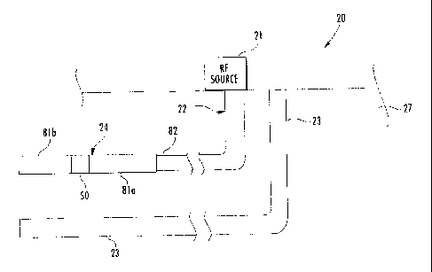
[0037] Referring initially to FIGS. 1-2, a hydrocarbon
recovery system 20 according to the present invention is now
described. The hydrocarbon recovery system 20 includes an
injector well 22, and a producer well 23 positioned within
respective wellbores in a subterranean formation 27 for
hydrocarbon recovery. The injector well 22 includes an
antenna assembly 24 at a distal end thereof. The hydrocarbon
recovery system 20 includes an RF source 21 for driving the
antenna assembly 24 to generate RF heating of the subterranean
formation 27 adjacent the injector well 22.
(0038] The antenna assembly 24 comprises a tubular antenna
element 28, for example, a center fed dipole antenna,
positioned within one of the wellbores, and a RF coaxial
transmission line positioned within the tubular antenna
element. The RF coaxial transmission line comprises a series
of coaxial sections 31a-31b coupled together in end-to-end
relation. The tubular antenna element 28 also includes a
plurality of tool-receiving recesses 27 for utilization of a
torque tool in assembly thereof. The coaxial sections 31a-31b
also include a plurality of tool-receiving recesses 42a-42b.
8
CA 02847366 2016-05-25
[0039] The antenna assembly 24 includes a dielectric spacer
25 between the tubular antenna element 28 and the RF coaxial
transmission line 31a-31b, and a dielectric spacer 26 for
serving as a centering ring for the antenna assembly 24 while
in the respective wellbore.
[0040] Referring now additionally to FIGS. 3-53, the RF
antenna assembly 24 comprises first and second tubular
conductors 81a-81b, and a feed structure 50 therebetween
defining a dipole antenna positioned within the respective
wellbore. The RF transmission line 82 extends within one of
the tubular conductors 81a. The feed structure 50 comprises a
dielectric tube 61, a first connector 60a coupling the RF
transmission line 82 to the first tubular conductor 81a, and a
second connector 60b coupling the RF transmission line to the
second tubular conductor 81b. For example, the dielectric
tube 61 may comprise a cyanate ester composite material (e.g.
quartz enhanced) or another suitable dielectric composite that
has mechanical strength for structural integrity, and absorbs
minimal amounts of radiated energy.
[0041] More specifically, the RF transmission line 82 may
comprise a series of coaxial sections coupled together in end-
to-end relation, each coaxial section comprising an inner
conductor 71, an outer conductor 72 surrounding the inner
conductor, and a dielectric 73 therebetween. The first
connector 60a couples the outer conductor 72 to the first
tubular conductor 81a, and the second connector 60b couples
the inner conductor 71 to the second tubular conductor 81b.
In the illustrated embodiment, the first and second connectors
60a-60b include a plurality of tool-receiving recesses 65a-65d
on an outer surface thereof. The tool-receiving recesses 65a-
65d are illustratively circular in shape, but in other
embodiments, may comprise other shapes, such as a hexagon
shape. The tool-receiving recesses 65a-65d are provided to
9
CA 02847366 2016-05-25
aid in using torque wrenches in assembling the antenna
assembly 24. As perhaps best seen in FIG. 4, the RF
transmission line 82 is affixed to the first connector 60a
with a plurality of bolts. Of course, other fasteners may be
used.
[0042] In the illustrated embodiment, the inner conductor
71 comprises a tube defining a first fluid passageway 85
therein (e.g. for the flow of cooling fluid/gas in). The
outer conductor 72 is illustratively spaced from the inner
conductor 71 to define a second fluid passageway 73 (e.g. for
cooling/gas out fluid). The passageways 85, 73 permit the
flow of selective gases and fluids that aid in the hydrocarbon
recovery process.
[0043] The feed structure 50 includes an intermediate
conductor 62 extending within the dielectric tube 61 and
coupling the inner conductor 71 to the second connector 60b.
For example, the intermediate conductor 62 illustratively
comprises a conductive tube (of a material comprising, e.g.,
copper, aluminum). Moreover, the RF transmission line 82
includes an inner conductor coupler 67 for coupling the inner
conductor 71 to the intermediate conductor 62, and first and
second dielectric spacers 74-75, each comprising a bore
therein for receiving the inner conductor coupler. The first
and second dielectric spacers 74-75 are shown without fluid
openings, but in other embodiments (FIG. 6), they may include
them, thereby permitting the flow of fluids within the
dielectric tube 61. Advantageously, the inner conductor
coupler 67 accommodates differential thermal expansion.
Additionally, the first and second tubular conductors 81a-81b
each comprises a threaded end 63a-63b, and the first and
second connectors 60a-60b each comprises a threaded end 86a-
86b engaging a respective threaded end of the first and second
tubular conductors for defining overlapping mechanical
CA 02847366 2016-05-25
threaded joints 64a-64b. The threaded ends 63a-63b of the
first and second tubular conductors 81a-81b each comprises a
mating face adjacent the first and second connectors 60a-60b.
The mating face includes a threading relief recess to provide
good contact at the outer extreme of the first and second
connectors 60a-60b. The overlapping mechanical threaded
joints 64a-64b provide for a hydraulic seal that seals in
fluid and gases within the antenna assembly 24.
[0044] The second connector 60b illustratively includes an
interface plate 58 mechanically coupled thereto, via
fasteners, and another inner conductor coupler 59. The
interface plate 58 illustratively includes openings (slits)
therein for permitting the controlled flow of coolant. In
some embodiments, the coolant would flow from the inner
conductor coupler 59 through the dielectric tube 61 and return
to the second fluid passageway 73. In these embodiments, the
first and second dielectric spacers 74-75 each include
openings therein for providing the flow (FIG. 6).
[0045] As perhaps best seen in FIGS. 5A and 5B, each of the
first and second connectors 60a-60b comprises a recess 66a-66b
for receiving adjacent portions of the dielectric tube 61. In
the illustrated embodiment, each recess comprises a circular
slot that is circumferential with regards to the first and
second connectors 60a-60b. Moreover, all edges in the
illustrated embodiment are rounded, which helps to reduce
arching in high voltage (HV) applications.
[0046] In one embodiment, the dielectric tube 61 is affixed
to each of the first and second connectors 60a-60b with a
multi-step process. First, the recesses 66a-66b are primed
for bonding, and then an adhesive material 99b, such as an
epoxy (e.g. EA9494 (Hysol EA 9394 high temperature epoxy
adhesive, other similar high temperature adhesives can be
used. This provides stability and strength in the bonded
11
CA 02847366 2016-05-25
joint.)), is placed therein. Thereafter, the first and second
connectors 60a-60b and the dielectric tube 61 are drilled to
create a plurality of spaced apart blind passageways 53a-53b,
i.e. the drill hole does not completely penetrate the first
and second connectors. The passageways 53a-53b are then
reamed, and for each passageway, a pin 78 is placed therein.
The passageways 53a-53b are then filled with an epoxy adhesive
77, such as Sylgard 186, as available from the Dow Corning
Corporation of Midland, Michigan, and then the surface is fly
cut to provide a smooth surface. The epoxy adhesive 77 forces
out and air pockets and insures structural integrity. A high-
temp adhesive, such as Loctite 609 (for cylindrical
assemblies), is applied just prior to assembly of the pin 78
in the passageway 53a-53b, the axial hole 76 in the pin
allowing gasses to escape on assembly.
[0047] Advantageously, the feed structure 50 isolates the
first and second tubular conductors 81a-81b of the dipole
antenna, thereby preventing arching for high voltage
applications in a variety of environmental conditions.
Moreover, the feed structure 50 is mechanically robust and
readily supports the antenna assembly 24. The dielectric tube
61 has a low power factor (i.e. the product of the dielectric
constant and the dissipation factor), which inhibits
dielectric heating of the feed structure 50. Moreover, the
materials of the feed structure 50 have long term resistance
to typical oil field chemicals, providing for reliability and
robustness, and have high temperature survivability without
significant degradation of the desirable properties.
[0048] In another embodiment, the feed structure 50 may
include a ferromagnetic tubular balun extending through the RF
transmission line 82 and to the dielectric tube 61,
terminating at the balun isolator. The balun surrounds the
inner conductor 71 and aids in isolating the inner conductor
12
CA 02847366 2016-05-25
and reducing common mode current.
[0049] Another aspect is directed to a method of making an
RF antenna assembly 24 to be positioned within a respective
wellbore in a subterranean formation 27 for hydrocarbon
resource recovery. The method includes providing first and
second tubular conductors 81a-81b and a feed structure 50
therebetween to define a dipole antenna to be positioned
within the respective wellbore, positioning an RF transmission
line 82 to extend within one of the tubular conductors 81a,
and forming the feed structure. The feed structure 50
comprises a dielectric tube 61, a first connector 60a coupling
the RF transmission line 82 to the first tubular conductor
81a, and a second connector 60b coupling the RF transmission
line to the second tubular conductor 81b.
[0050] Referring again to FIGS. 1-4, an RF antenna assembly
24 according to the present invention is now described. The
RF antenna assembly 24 is configured to be positioned within a
wellbore in a subterranean formation 27 for hydrocarbon
resource recovery. The RF antenna assembly 24 comprises first
and second tubular conductors 81a-81b and a dielectric
isolator 50 therebetween. The dielectric isolator 50
comprises a dielectric tube 61 having opposing first and
second open ends, a first tubular connector 60a comprising a
first slotted recess 66a receiving therein the first open end
of the dielectric tube, and a second tubular connector 60b
comprising a second slotted recess 66b receiving therein the
second open end of the dielectric tube.
[0051] More specifically, the dielectric tube includes a
first plurality of passageways 98a therein adjacent the first
open end and through the first slotted recess 66a, and a
second plurality of passageways 98b therein adjacent the
second open end and through the second slotted recess 66b.
The first tubular connector 60a includes a first plurality of
13
CA 02847366 2016-05-25
blind 53a-53b openings therein aligned with the first
plurality of passageways 98a, and the second tubular connector
60b includes a second plurality of blind openings 53c-53d
therein aligned with the second plurality of passageways 98b.
[0052] The RF antenna assembly 24 includes a first
plurality of pins extending through the first pluralities of
passageways and blind openings 98a, 53a-53b, and a second
plurality of pins 78 extending through the second pluralities
of passageways 98b and blind openings 53c-53d. Although the
first plurality of pins is not depicted, the skilled person
would appreciate they are formed similarly to the second pins
78. The RF antenna assembly 24 further comprises adhesive 99b
securing the first and second tubular connectors 60a-60b to
the respective first and second open ends.
[0053] Additionally, the first tubular connector 60a
includes a first threaded surface 86a for engaging an opposing
threaded end 63a of the first tubular conductor, and the
second tubular connector 60b includes a second threaded
surface 86b for engaging an opposing threaded end 63b of the
second tubular conductor. The first tubular connector 60a
illustratively includes a first plurality of tool-receiving
recesses 65a-65b on a first outer surface thereof, and the
second tubular connector 60b illustratively includes a second
plurality of tool-receiving recesses 65c-65d on a second outer
surface thereof. The dielectric isolator 50 illustratively
. includes an inner conductor 62 extending within the dielectric
tube.
[0054] Referring additionally to FIG. 6, the first tubular
connector 60a illustratively includes an inner interface plate
92 (outer conductor plate), an outer interface plate 91, and
an 0-ring 94 between the interface plates for providing a
tight seal. The first tubular connector 60a illustratively
includes a pair of 0-rings 93a-93b between the outer interface
14
CA 02847366 2016-05-25
plate 91 and the first threaded surface 86a. The outer
interface plate 91 illustratively includes a plurality of
circumferential openings 96a-96b, which each receives
fasteners therethrough, such as screws or pins. The pair of
0-rings 93a-93b provides a good seal to control the fluid
paths for the cooling oil, and gas paths (as discussed above).
[0055] The fasteners physically couple the outer interface
plate 91 to the first tubular connector 60a. The electrical
coupling between the outer interface plate 91 and the first
tubular connector 60a is at a contact point 89. The coupling
also includes a relief recess 95 to generate high force on a
defined rim to ensure "metal to metal" contact at a certain
pressure, and to guarantee the electrical path. The inner
interface plate 92 illustratively includes a plurality of
openings 87a-87b for similarly receiving fasteners to
mechanically couple the inner and outer interface plates 91-92
together.
[0056] The large number of small fasteners in the inner and
outer interface plates 91-92 decreases the radial space for
connection, and increases HV standoff distances inside the
dielectric isolator 50. Also, the inner and outer interface
plates 91-92 have rounded surfaces to increase HV breakdown.
[0057] Another aspect is directed to a method of assembling
an RF antenna assembly 24 to be positioned within a wellbore
in a subterranean formation 27 for hydrocarbon resource
recovery. The method comprises coupling first and second
tubular conductors 81a-81b and a dielectric isolator 50
therebetween, the dielectric isolator comprising a dielectric
tube 61 having opposing first and second open ends, a first
tubular connector 60a comprising a first slotted recess 66a
receiving therein the first open end of the dielectric tube,
and a second tubular connector 60b comprising a second slotted
recess 66b receiving therein the second open end of the
CA 02847366 2016-05-25
dielectric tube.
[0058] In the illustrated embodiment, the dielectric
isolator 50 couples together two dipole element tubular
conductors 81a-81b, but in other embodiments. The tubular
connectors 60a-60b of the dielectric isolator 50 may omit the
electrical couplings to the inner conductor 71 and outer
conductor 72 of the RF transmission line 82. In these
embodiments, the RF transmission line 82 passes through the
dielectric isolator 50 for connection further down the
borehole, i.e. a power transmission node.
[0059] Referring now additionally to FIG. 7, another
embodiment of the RF antenna assembly 24' is now described.
In this embodiment of the RF antenna assembly 24', those
elements already discussed above with respect to FIGS. 1-6 are
given prime notation and most require no further discussion
herein. This embodiment differs from the previous embodiment
in that this RF antenna assembly 24' includes a series of
tubular dipole antennas 102a'-102c', 103a'-103b' to be
positioned within the wellbore, each tubular dipole antenna
comprising a pair of dipole elements 102a'-103a', 103a'-102b',
103b'-102c'. The RF antenna assembly 24' includes an RF
transmission line 82' extending within the series of tubular
dipole antennas 102a'-102c', 103a'-103b', and a respective
coupling structure 104'-107', 111' between each pair of dipole
elements and between the series of tubular dipole antennas.
Each coupling structure 104'-107', 111' comprises a dielectric
tube 61' mechanically coupling adjacent dipole elements 102a'-
103a', 103a'-102b', 103b'-102c', and a pair of tap connectors
60a'-60b' carried by the dielectric tube and electrically
coupling the RF transmission line 82' to a corresponding
dipole element. Additionally, the RF antenna assembly 24'
includes 2/2 dipoles elements 102a'-103a', 103a'-102b', 103b'-
102cf, and a balun element 101' coupled to the first coupling
16
CA 02847366 2016-05-25
structure 111'.
[0060] More specifically, the RF transmission line 82'
comprises an inner conductor 71', an outer conductor 72'
surrounding the inner conductor, and a dielectric (e.g. air or
cooling fluid) therebetween. The respective coupling
structures comprise first 105'-106' and second 104', 107',
111' sets thereof. The tap connectors 60a'-60b' of the first
set of coupling structures 105'-106' electrically couple the
outer conductor 72' to the corresponding dipole elements
103a'-103b'. The tap connectors of the second set of coupling
structures 104', 107', 111' electrically couple the inner
conductor 71' to the corresponding dipole elements 102a'-
102c'.
[0061] Referring now additionally to FIGS. 8-9, in the
illustrated embodiment, each first set coupling structure
105'-106' comprises an electrically conductive support ring
110' surrounding the outer conductor 72' and being in the tap
connector 60b' for coupling the outer conductor to the
corresponding dipole element 103a'-103b'. Each first set
coupling structure 105'-106' illustratively includes a
circular finger stock 185' (e.g. beryllium copper (BeCu))
surrounding the electrically conductive support ring 110' and
for providing a solid electrical coupling. As perhaps best
seen in FIG. 9, the electrically conductive support ring 110'
includes a plurality of passageways for permitting the flow of
fluid therethrough.
[0062] Referring now additionally to FIGS. 10-12, in the
illustrated embodiment, each second set coupling structure
104', 107', 111' comprises a dielectric support ring 120'
surrounding the outer conductor 72' and in the tap connector
60b', and an electrically conductive radial member 125'
extending through the dielectric support ring and the outer
conductor, and coupling the inner conductor 71' to the
17
CA 02847366 2016-05-25
corresponding dipole element 102a'-102c'. Each second set
coupling structure 104', 107', 111' illustratively includes a
first circular conductive coupler 123' surrounding the inner
conductor 71', and a second circular conductive coupler 127'
surrounding the outer conductor 72'.
[0063] Each second set coupling structure 104', 107', 111'
illustratively includes an insulating tubular member 122'
surrounding the electrically conductive radial member 125' and
insulating it from the outer conductor 72'. The insulating
tubular member 122' is within the dielectric support ring
120'. Additionally, each second set coupling structure 104',
107', 111' illustratively includes a cap portion 126' having a
finger stock 121' (e.g. beryllium copper (BeCu)) for providing
a good electrical connection to the corresponding dipole
element 102a'-102c', and a radial pin 186' extending
therethrough for coupling the cap portion to the electrically
conductive radial member 125' (also mechanically coupling the
dielectric support ring 120' and the insulating tubular member
122' to the outer conductor). As shown, the path of the
electrical current from the inner conductor 71' to the tap
connector 60b' is noted with arrows.
[0064] Referring now additionally to FIGS. 13A-13C, the
steps for assembling the second set coupling structure 104',
107', 111' includes coupling the second circular conductive
coupler 127' to surround the outer conductor 72', and coupling
the tubular member 122' to the outer conductor with the cap
portion 126'. The dielectric support ring 120' comprises half
portions that are assembled one at a time, and coupled
together with fasteners. Also, the cap portion 126' allows
the outer isolator to slide and thread into place while
maintaining electrical contact.
[0065] Advantageously, the second set coupling structure
104', 107', 111' may allow for current and voltage transfer to
18
CA 02847366 2016-05-25
the transducer element while maintaining coaxial transmission
line 82' geometry, inner and outer conductor fluid paths 73',
85', coefficient of thermal expansion (CTE) growth of
components, installation concept of operations (CONOPS) (i.e.
torque/ twisting), and fluid/gas path on exterior of
transmission line. Also, the power tap size can be customized
to limit current and voltage. In particular, the size and
number of electrical "taps" result in a current dividing
technique that supplies each antenna segment with the desired
power. Also, the RF antenna assembly 24' provides flexibility
in designing the number and radiation power of the antenna
elements 102a'-102c', 103a'-103b'.
[0066] Also, the RF antenna assembly 24' allows for the
formation of as many antenna segments as desired, driven from
a single RF coaxial transmission line 82'. This makes for a
selection of frequency independent of overall transducer
length. Also, the RF antenna assembly 24' allows "power
splitting" and tuning, by selection of the size and number of
center conductor taps, and maintains coaxial transmission line
82' geometry, allowing the method for sequential building of
the coax/antenna sections to be maintained. The RF antenna
assembly 24' can be field assembled and does not require
specific "clocking" of the antenna exterior with respect to
the inner conductor "tap" points, assembly uses simple tools.
[0067] Furthermore, the RF antenna assembly 24' may permit
sealing fluid flow to allow cooling fluid/gas and to allow for
pressure balancing of the power node and antenna. The RF
antenna assembly 24' accommodates differential thermal
expansion for high temperature use, and utilizes several
mechanical techniques to maintain high RF standoff distances.
Also, RF antenna assembly 24' has multiple element sizes that
can be arrayed together, allowing for the transducer to be
driven at more than one frequency to account different
19
CA 02847366 2016-05-25
subterranean environments along the length of the wellbore.
[0068] Additionally, the inner conductor 71' comprises a
tube defining a first fluid passageway 85' therein, and the
outer conductor 72' is spaced from the inner conductor to
define a second fluid passageway 73'. Each dielectric tube
61' includes opposing open ends, and with opposing tap
connectors 60a'-60b'. Each opposing tap connector 60a'-60b'
is tubular and comprises a slotted recess 66a'-66b' receiving
therein the respective opposing open end of the dielectric
tube 61'. Also, each tubular opposing tap connector 60a'-60b'
includes a threaded surface 86e-86b' for engaging an opposing
threaded end 63e-63b' of the corresponding dipole element
102a'-102c', 103e-1031p', and a first plurality of tool-
receiving recesses 65a-65d on a first outer surface thereof.
[0069] Another aspect is directed to a method of making a
RF antenna assembly 24' operable to be positioned within a
wellbore in a subterranean formation 27' for hydrocarbon
resource recovery. The method comprises positioning a series
of tubular dipole antennas 102a'-102c', 103e-103b' within the
wellbore, each tubular dipole antenna comprising a pair of
dipole elements, positioning an RF transmission line 82' to
extend within the series of tubular dipole antennas, and
positioning a respective coupling structure 105'-107', 111'
between each pair of dipole elements and between the series of
tubular dipole antennas. Each coupling structure 105'-107',
111' comprises a dielectric tube 61' mechanically coupling
adjacent dipole elements 102a'-102c', 103a'-103b', and at
least one tap connector 60a'-60b' carried by the dielectric
tube and electrically coupling the RF transmission line 82' to
a corresponding dipole element.
[0070] Referring now to FIGS. 14A-15C, the heating pattern
of the RF antenna assembly 24' is shown. Diagrams 140-142
show the heating pattern with cr=14, o=0.003 S/m, and diagrams
CA 02847366 2016-05-25
150-152 show the heating pattern with Er=30, o=0.05 S/m.
Advantageously, the RF antenna assembly 24' collinear array
configuration provides a uniform heating pattern along the
axis of the array. Also, the football shaped desiccation
region is based on heating patterns of a dipole antenna. For
the sake of maximum uniformity between models, this
desiccation shape was used for alternate antenna designs also.
The actual shape of the desiccation region may be different.
[0071] Referring now additionally to FIGS. 16A-16B, a Smith
Chart 160 (Frequency Sweep: 5.2- 5.4 MHz) and another
associate diagram 165 illustrate performance of the RF antenna
assembly 24'. Sensitivity: 1) Impedance is comparable to a
dipole as the pay zone moves from saturation (solid with X
mark, plain dashed line) to desiccation (solid line with
circle, and dashed line with square mark). 2) Impedance is
managed over the pay zone corner cases for low and high Er and
o.
Name Fmq Ang Mag RX
ml 5.8791 -154.57531 0.0892
I 0.8485 - 0.0655i
m2 6.1761 1.1308 1 0.1360 1.3148 +
0.0072i
m3 5.8667 -151.6645 0.0715
0.8797 - 0.0600i
m4 6.1885 3.0302 0.0062 11.0124 + 0.0007i
m5 5.8667 1-159.9952 i
0.0345 0.9369 - 0,0222i
m6 6.1390 173.9086 0.0559
10.8947 + 0.0106i
Table 1: Data Points for Smith Chart (FIG. 16A)
[0072] Other features relating to RF antenna assemblies are
disclosed in co-pending applications: titled "RF ANTENNA
ASSEMBLY WITH FEED STRUCTURE HAVING DIELECTRIC TUBE AND
RELATED METHODS," Attorney Docket No. GCSD-2558 (61874); and
titled "RF ANTENNA ASSEMBLY WITH SERIES DIPOLE ANTENNAS AND
COUPLING STRUCTURE AND RELATED METHODS," Attorney Docket No.
GCSD-2630 H8904 (61898), all incorporated herein by reference
in their entirety.
21
CA 02847366 2016-05-25
[0073] Many modifications and other embodiments of the
invention will come to the mind of one skilled in the art
having the benefit of the teachings presented in the foregoing
descriptions and the associated drawings. Therefore, it is
understood that the invention is not to be limited to the
specific embodiments disclosed, and that modifications and
embodiments are intended to be included within the scope of
the appended claims.
22