Note: Descriptions are shown in the official language in which they were submitted.
CA 02848220 2014-03-07
WO 2013/034890 PCT/GB2012/052123
- 1 -
UV Liquid Steriliser
This invention relates to methods and apparatus for disinfecting fluids and,
in particular to
methods and apparatus for disinfecting drinks and comestible fluids such as
syrups and
concentrates.
To ensure that all of a fluid is properly irradiated, disinfection using ultra-
violet (UV)
radiation requires that the fluid be extremely thinly dispersed and/or that it
be very
thoroughly mixed during irradiation. To achieve practical rates of volume
throughput for
industrial processes whilst meeting the required standards for disinfection
rates (5-Log
kill or better) had been thought technically difficult to achieve using UV
methods. Our
previous International Patent Application, publication number W02010/125389
discloses
an advantageous method and system for achieving this.
We have recognised a problem that comestible fluids differ substantially in
their flow
properties and interaction with UV light. We have further recognised that it
is desirable to
minimise both the UV power applied and the irradiation time to increase the
energy
efficiency and volume throughput of a commercial processing plant. It had
previously
been thought that passing fluids through UV disinfection apparatus at
excessive speed
would reduce efficacy by reducing irradiation time. However we have now shown
that,
dependent on the characteristics of the fluid efficient flow and acceptable
disinfection
rates are achievable. We have also now recognised that certain liquids are
prone to
growths of agglomerations (clumps) of micro organisms and that the organisms
at the
centre of these clumps may bypass a conventional disinfector unharmed but we
have
dealt with this issue.
After further work we have demonstrated that gains in efficiency and the rate
of
disinfection can be achieved by selecting particular dimensions and flow rates
for
particular fluids without needing to increase the overall size or power of the
apparatus.
This selection enables relatively low power apparatus to achieve (and exceed)
commercially acceptable disinfection standards whilst providing sufficient
throughput to
meet operational need in industrial food preparation facilities. Without
wishing to be
bound by theory it is thought that, if turbulent flow in a thin film can be
achieved, high
shear stresses in the fluid exist which promote the disintegration of
agglomerations of
CA 02848220 2014-03-07
WO 2013/034890
PCT/GB2012/052123
- 2 -
microorganisms enabling these organisms to be more properly exposed to UV
radiation.
We present herein a series of examples to demonstrate the efficacy of our new
methods
and of apparatus constructed according to the principles demonstrated herein.
In an aspect there is provided a fluid steriliser comprising a plurality of
units coupled in
parallel between a common fluid source and a common fluid outlet, each unit
comprising:
a fluid duct having a UV transmissive wall providing a surface area for
irradiation,
wherein the cross section of the duct is between 1x10⁻⁴ m2 and 1x10⁻³ m2 and
the
thickness of the duct defines the depth of fluid flow adjacent the UV
transmissive wall;
a source of UV radiation arranged to irradiate fluid flowing in the duct
through the UV
transmissive wall such that the UV radiation incident on fluid in the duct has
a UV power
density; a plurality of mixing stages configured to provide turbulent flow in
the fluid and
spaced apart along the length of the duct wherein the segments of the duct
between the
mixing stages are arranged to provide at least partially laminar flow adjacent
the UV
transmissive wall; a flow control means arranged to control the linear speed
of fluid flow
along the duct based on the length of the duct and the UV power density so
that at least
300 Joules of UV energy per square metre of the surface area for irradiation
is provided
to the fluid during the dwell time of the fluid in the duct. This and other
examples of the
invention have the advantage of providing effective cold sterilisation of
comestible fluids
in practical commercial systems.
In some examples the mixing stages comprise UV transmissive material.
Preferably
wherein the mixing stages are arranged so that UV light from the UV source can
reach
the interior surfaces of the mixing stages when the mixing stage is filled
with a UV
transmissive fluid. This has the advantage that, when the mixing stages are
filled with a
UV transmissive fluid, such as cleaning water, the unit can be irradiated with
UV light to
sterilise the mixing stages.
In some possibilities the flow control means is configured such that, in use
with fluids
having a viscosity of less than 200 centipoise, the pressure drop across the
fluid duct is
less than 8 bar. In some possibilities the mixing stations comprise baffles
arranged at an
angle of at least 700 to the direction of the at least partially laminar flow
adjacent the UV
CA 02848220 2014-03-07
WO 2013/034890
PCT/GB2012/052123
- 3 -
transmissive wall. Preferably the flow control means is configured to control
the flow of
fluid along the duct such that the average linear speed of the fluid flow
between the
baffles is between 0.6 and 1.8 meters per second, still more preferable
between 1.0
meters per second and 1.4 metres per second. These and other examples of the
invention have the advantage of providing effective mixing of fluids without
modifying
their texture or consistency in a manner which is noticeable to consumers.
In an aspect there is provided a fluid treatment apparatus comprising a
plurality of
mutually similar units, each unit comprising plurality of elongate tubular
ducts, a fluid inlet
in fluid communication with a fluid outlet via the plurality of elongate
tubular ducts, each
duct having:
a UV transmissive inner wall spaced from an outer wall to enable fluid flow
along
the tubular duct between the inner wall and outer wall;
a plurality of baffles distributed along the length of the duct and arranged
substantially perpendicular to the direction of the fluid flow;
the apparatus further comprising a flow control means configured to control
the
flow of fluid along the duct such that the average linear speed of the fluid
flow between
the baffles is between 1.0 and 1.6 meters per second. We have surprisingly
found that
this range of linear speeds provides more effective disinfection for high
volume
throughput. Without wishing to be bound by theory it is believed that, at this
range of
linear speeds fluid mixing is enhanced without reducing the effectiveness of
irradiation.
In one possibility the interior surface of the inner wall of the duct has a
diameter of at
least 38.5mm. In one possibility the interior surface of the inner wall of the
duct has a
diameter of at least 39mm. In one possibility the interior surface of the
inner wall of the
duct has a diameter of at least 39.5mm. In one possibility the interior
surface of the outer
wall of the duct has a diameter of less than 54mm. In one possibility the
interior surface
of the outer wall of the duct has a diameter of less than 52mm. In one
possibility the
interior surface of the outer wall of the duct has a diameter of less than
51mm. In one
possibility the interior surface of the outer wall of the duct has a diameter
of less than
50.5mm.
In an aspect there is provided a method of disinfecting comestible fluid
comprising
CA 02848220 2014-03-07
WO 2013/034890
PCT/GB2012/052123
- 4 -
providing fluid into a fluid treatment apparatus comprising an elongate
tubular duct
having:
a duct inlet, a duct outlet, and a UV transmissive inner wall spaced from an
outer
wall to enable fruit juice to flow along the tubular duct between the inner
wall and outer
wall, wherein the cross section of the duct through which fluid can flow has
an area of at
least 1x1 0-4m2 and less than 1x1 0-3m2; a plurality of baffles distributed
along the length of
the duct and arranged substantially perpendicular to the direction of the
flow;
irradiating the fluid through the UV transmissive wall with UV radiation;
controlling the pressure of the juice such that the pressure difference
between the
duct inlet and the duct outlet is less than 0.4 bar and more than than 0.05
bar. These
examples of the invention have the advantage of improved disinfection of the
fluid for a
given irradiative power. This method has been found to be particularly
effective in the
disinfection of milk and fruit juices. Without wishing to be bound by theory
it is thought
that the consistency and UV transmitting characteristics of these fluids mean
that under
these pressure differentials through ducts of this size, very effective mixing
is provided.
Preferably the cross section of the duct through which fluid can flow is at
least 2x10⁻⁴m2,
still more preferably the cross section of the duct through which fluid can
flow is at least
3x10⁻⁴m2. In some possibilities the cross section of the duct is at least 4x10-
4m2. In some
possibilities the cross section of the duct is at least 6x10⁻⁴m2. Preferably
the cross
section of the duct through which fluid can flow is less than 9x10⁻⁴m2, still
more preferably
the cross section of the duct through which fluid can flow is less than 8x10-
4m2. In some
possibilities the cross section of the duct is less than 7.9x10⁻⁴m2.
In some possibilities the pressure difference between the duct inlet and the
duct outlet is
greater than .08 bar, preferably greater than 0.1 bar. In some possibilities
the pressure
difference between the duct inlet and the duct outlet is less than .2 bar,
preferably less
than 0.19 bar. In some possibilities a pressure difference of about 0.16 bar
may be
applied. These and other examples of the invention have the advantage of
exceeding
the commercially acceptable disinfection rates for fruit juices (better than 5
log kill).
In an aspect there is provided a method of disinfecting edible oils comprising
providing
edible oil into a fluid treatment apparatus comprising an elongate tubular
duct having:
CA 02848220 2014-03-07
WO 2013/034890
PCT/GB2012/052123
- 5 -
a duct inlet, a duct outlet, and a UV transmissive inner wall spaced from an
outer
wall to enable fluid to flow along the tubular duct between the inner wall and
outer wall,
wherein the cross section of the duct through which fluid can flow has an area
of at least
1x10⁻⁴m2; a plurality of baffles distributed along the length of the duct and
arranged
substantially perpendicular to the direction of the flow;
irradiating the juice through the UV transmissive wall with UV radiation;
controlling the pressure of the edible oil such that the pressure difference
between
the duct inlet and the duct outlet is greater than 0.9 bar and less than 1.7
bar, wherein
the edible oil has a viscosity of at least 30cP (mPa.$) and less than 70cP
(mPa.$). These
examples of the invention have the advantage of improved disinfection of the
oils for a
given irradiative power.
Preferably the cross section of the duct through which fluid can flow is at
least 2x10⁻⁴m2,
still more preferably the cross section of the duct through which fluid can
flow is at least
3x10⁻⁴m2. In some possibilities the cross section of the duct is at least
3.2x10⁻⁴m2.
Preferably the cross section of the duct through which fluid can flow is less
than 6x10
4m2, still more preferably the cross section of the duct through which fluid
can flow is less
than 5x10⁻⁴m2. In some possibilities the cross section of the duct is less
than 3.4x10⁻⁴m2.
In some possibilities the pressure difference between the duct inlet and the
duct outlet is
greater than 1.3 bar, preferably greater than 1.4 bar. In some possibilities
the pressure
difference between the duct inlet and the duct outlet is less than 1.7 bar,
preferably less
than 1.6 bar. These and other examples of the invention have the advantage of
exceeding the commercially acceptable disinfection rates for oils (better than
5 log kill)
In an aspect there is provided a method of disinfecting beer, milk or vinegar
comprising
providing milk into a fluid treatment apparatus comprising an elongate tubular
duct
having:
a duct inlet, a duct outlet, and a UV transmissive inner wall spaced from an
outer
wall to enable fluid to flow along the tubular duct between the inner wall and
outer wall,
wherein the cross section of the duct through which fluid can flow has an area
of at least
1x10⁻⁴m2; a plurality of baffles distributed along the length of the duct and
arranged
substantially perpendicular to the direction of the flow;
irradiating the juice through the UV transmissive wall with UV radiation;
CA 02848220 2014-03-07
WO 2013/034890
PCT/GB2012/052123
- 6 -
controlling the pressure of the milk or vinegar such that the pressure
difference
between the duct inlet and the duct outlet is greater than 0.3 bar and less
than 0.9 bar.
These examples of the invention have the advantage of improved disinfection of
the milk
for a given irradiative power.
Preferably the cross section of the duct through which fluid can flow is at
least 2x10⁻⁴m2,
still more preferably the cross section of the duct through which fluid can
flow is at least
3x10⁻⁴m2. In some possibilities the cross section of the duct is at least
3.2x10⁻⁴m2.
Preferably the cross section of the duct through which fluid can flow is less
than 6x10-
4n-12, still more preferably the cross section of the duct through which fluid
can flow is less
than 5x10⁻⁴m2. In some possibilities the cross section of the duct is less
than 3.4x10⁻⁴m2.
In some possibilities the pressure difference between the duct inlet and the
duct outlet is
greater than 0.4 bar, preferably greater than 0.5 bar, preferably the pressure
difference is
0.62 bar for milk and 0.66 bar for vinegar.
In some possibilities the pressure difference between the duct inlet and the
duct outlet is
less than 0.8 bar, preferably less than 0.7 bar. These and other examples of
the
invention have the advantage of exceeding the commercially acceptable
disinfection
rates for milk and vinegar whilst reducing the power consumption of the
apparatus per
unit volume of fluid to be disinfected.
In accordance with the present disclosure there is provided a fluid treatment
apparatus,
comprising an elongate tubular duct having a fluid inlet and outlet at
opposite ends
thereof an elongate source of UV radiation extending longitudinally of said
elongate
tubular duct, and a mixing device disposed between adjacent longitudinal
portions of the
duct for diverting all of the fluid flowing along a first said portion of the
duct through fluid
mixing means in the device and for returning the mixed fluid to a second said
portion of
the duct.
The mixing of all the fluid ensures that all parts of the fluid come within
sufficient proximity
of the UV source.
Preferably said mixing means defines a tortuous flow path through which the
fluid flows,
CA 02848220 2014-03-07
WO 2013/034890 PCT/GB2012/052123
- 7 -
the flow along the passage serving to provide a high degree of mixing.
Preferably the flow path comprises one of more turns of 90 degrees and
preferably the
flow passage turns the fluid though at least 180 degrees between adjacent
longitudinal
portions of the duct. Good mixing of a liquid can be achieved by continually
changing its
direction through 90 degree bends or preferably through 180 degree bends. The
continual sudden velocity changes imparted to the liquid by this technique
ensures all
constituents of the liquid are mixed. Preferably at least a portion of the
flow path is
arranged to be irradiated by UV radiation emitted by said source.
Preferably the duct defines a flow passage for the fluid in which all of the
fluid is no more
than 10mm and preferably no more than 5mm away from the surface of the UV
source,
the source forming at least a portion of the longitudinal wall of the flow
passage. In this
way the fluid flows as a thin film over the UV source. The surface
constituents of the thin
film are continually being changed due to the mixing effect.
Preferably the UV source extends along the central axis of the duct and is
surrounded by
the flow passage.
Preferably the UV source comprises an elongate lamp disposed inside a tube
which is
preferably formed of quartz or another material which is a good transmitter of
UV
radiation.
Preferably the tube is coated or covered with a material arranged to maintain
the integrity
of the tube should it break, thereby preventing contamination of the fluid
with potential
harmful pieces of the tube material. Preferably the coating or covering
material
comprises fluorinated ethylene propylene.
Preferably a plurality of said devices are provided along the length of the
duct so that the
fluid is mixed more than once.
Preferably the inlet and outlet communicate with respective manifolds at
opposite ends of
the duct.
CA 02848220 2014-03-07
WO 2013/034890
PCT/GB2012/052123
- 8 -
Preferably the UV source extends into one or both manifolds.
Also, in accordance with the disclosure, there is provided a fluid
disinfection system
comprising a plurality of the above-mentioned apparatus connected in series to
increase
the disinfection effect or in parallel to increase the flow rate of the
disinfected fluid or
both.
A summarisation of the disclosure and the benefits thereof is as follows: -
Disinfection
system with no moving parts - all parts may be stationary therefore the
reliability of the
system is high.
- Room temperature (change to cold) disinfection system - the process is
substantially a
cold process.
- Can withstand the industry cleaning pressures - all parts are able to
withstand
pressures of 10 bar and beyond.
- Produces a consistent thin film of liquid - the gap between the quartz
tube and the inner
surface of the duct provides a consistent liquid film thickness.
- Continually and thoroughly mixes the fluid
- The mixing devices are placed at intervals along the length of the apparatus
forcing the
fluid to change direction and hence the fluid velocity ensuring constant and
thorough
mixing of the fluid as it flows through the system.
Embodiments of this invention will now be described by way of example only and
with
reference to the accompanying drawings, in which;
Figure 1 shows a plan view with part section of a first embodiment of fluid
disinfection
apparatus;
Figure 2 shows a plan view with part section of a second embodiment of fluid
disinfection
apparatus;
Figure 3 shows a plan view with part section of a third embodiment of fluid
disinfection
apparatus;
CA 02848220 2014-03-07
WO 2013/034890
PCT/GB2012/052123
- 9 -
Figure 4 shows an exploded view of a mixing device for a fluid disinfection
apparatus;
Figure 5 shows an exploded view of a mixing device for a fluid disinfection
apparatus;
Figure 6 shows a sectional view of a fluid disinfection apparatus in
accordance with the
invention;
Figure 7 shows a plan view of the apparatus of Figure 6; Figure 8 shows an
exploded
view of a portion of a fluid disinfection apparatus;
Figure 9 shows an exploded view of a portion of a fluid disinfection apparatus
in
accordance with the invention;
Figure 10 shows a section AA through the fluid disinfection apparatus shown in
Figure 1;
Figure 11 shows an expansion joint for use with a fluid steriliser
Figure 12 shows a plot of the number of tubes against the log kill rate in
apple juice
infected with salmonella;
Figure 13 shows a plot of the number of tubes against the log kill rate in
apple juice
infected with cysptsodoridium;
Figure 14 shows a plot of the number of tubes against the log kill rate in
apple juice
infected with bacillus subtillis spores;
Figure 15 shows a plot of the number of tubes against the log kill rate in
apple juice
infected with alicydobacillus spores;
Figure 16 shows a plot of the number of tubes against the log kill rate in
full fat milk
infected with Mycobacterium tuberculosis;
Figure 17 shows a plot of the number of tubes against the log kill rate in
full fat milk
infected with bacillus subtillis spores;
Figure 18 shows a plot of the number of tubes against the log kill rate in
full fat milk
infected with listeria;
Figure 19 shows a plot of the number of tubes against the log kill rate in
orange juice
infected with aspergillus niger spores;
Figure 20 shows a plot of the number of tubes against the log kill rate in
orange juice
infected with alicyclobacillus spores; and
Figure 21 shows a plot of the number of tubes against the log kill rate in
orange juice
infected with ecoli 157;
CA 02848220 2014-03-07
WO 2013/034890
PCT/GB2012/052123
- 10 -
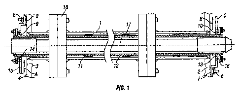
Referring to Figure 1 of the drawings in the first embodiment of the fluid
disinfection
apparatus a reaction chamber 1 is connected between end plates 2 & 3.
Preferably the
reaction chamber is welded to the end plates such that the welds are polished
to provide
a hygienic food grade seal.
Positioned adjacent to the reaction chamber is an inlet manifold 4 and an
outlet manifold
5 which are attached to the end plates 2 & 3 by fastenings 6. The inlet
manifold 4 and
outlet manifold 5 are made watertight by seals 7 & 8 which are clamped between
the inlet
and outlet manifolds 4 & 5 and the end plates 2 & 3.
A tubular sleeve 11 is positioned longitudinally centrally and concentrically
inside the
reaction chamber 1 such that it protrudes through the end plates 2 & 3 and
through the
holes 9 & 10 in the inlet and exit manifolds 4 & 5.
Preferably the tubular sleeve is a good transmitter of the germicidal
wavelengths (220nm
- 280nm).
Preferably the tubular sleeve is made of quartz.
Preferably the quartz sleeve is coated with a material which substantially
transmits the
germicidal wavelengths.
Preferably the coating material is substantially resilient in nature and is
able to contain all
quartz debris in the event of the quartz tube rupturing.
Preferably the material is Teflon FEP.
Means are provided to form a small concentric gap 12 between the tubular
sleeve 11
and the inside wall of the reaction chamber. By selecting the dimensions of
the outer
diameter of the tubular sleeve 11 to be slightly smaller than the inner
diameter of the
CA 02848220 2014-03-07
WO 2013/034890 PCT/GB2012/052123
- 1 1 -
reaction chamber 1 , the gap 12 produced is the dimensional difference between
the two.
Means are provided to make a water tight seal between the tubular sleeve 11
and the
inlet and outlet manifolds 4 & 5 in the form of a seal 13 & 14 positioned on
the
circumference at each end of the tubular sleeve 11 adjacent to the holes 9 &
10 in the
inlet and outlet manifolds 4 & 5. The seal is compressed by clamping plates 15
& 16
forming a watertight seal between the inlet and outlet manifolds 4 & 5 and the
tubular
sleeve 11.
The reaction chamber 1 , tubular sleeve 11 and the inlet and outlet manifolds
4 & 5 form
a watertight assembly such that liquid can flow in through the inlet manifold
4, through
the gap 12 and out through the outlet manifold 5.
Preferably the seals 13 & 14 are made of UV resistant material.
Preferably the material is silicone rubber, Viton, PTFE or Teflon FEP.
Preferably the seals 13 & 14 are designed to be flexible such that any
differential
expansion between the body of the reaction chamber 1 and the tubular sleeve 11
is
accommodated whilst the seals 13 & 14 still remain sealed.
Means are provided to radiate UV germicidal wavelengths (220nm - 280nm) into
the
gap12 in the form of a UV lamp 17 positioned inside the tubular sleeve 11
which when
energised radiate germicidal wavelengths into the gap through the wall of the
tubular
sleeve 11 .
Preferably the lamp 17 is positioned longitudinally centrally and
concentrically inside the
tubular sleeve 11 to provide consistent and even radiation into the gap 12.
Means are provided to mix the liquid as it passes through the disinfector in
the form of
mixing devices 18 positioned along the body of the reaction chamber 1 whereby
the flow
in the gap12 is diverted into and through the mixing device 18. The mixing
device 18
forces the liquid to traverse a flow path which causes it to change direction
and hence
velocity to create a thorough mixing of the fluid as it passes through the
device.
CA 02848220 2014-03-07
WO 2013/034890
PCT/GB2012/052123
- 12 -
Preferably the mixing device 18 has no moving parts.
Preferably the mixing device 18 forces the liquid into at least one 180 degree
bend.
Preferably the mixing device 18 is made of material which is substantially
resistant to
germicidal radiation.
Preferably the outside body of the mixing device18 is made of a food grade
standard
material.
Preferably the outside body of the mixing device18 is made of 316 grade
stainless steel.
Preferably the internal materials of the mixing device 18 are made of PTFE or
Teflon FEP
or another suitable material.
The general fluid flow is shown by the arrows A & B and the intervening
arrows.
Referring to Figure 5 of the drawings shows a mixing device for the apparatus
comprising circular flanges 2 & 3 attached to the body of the reaction chamber
1.
Flange 2 has shallow grooves cut into its face which act as channels for the
liquid. The
top groove 4 rises vertically from the centre of the flange 2 then moves in an
arc in a
clockwise direction for a distance around the top face of the flange 2. The
bottom groove
5 falls vertically from the centre of the flange 2 then moves in an arc in a
clockwise
direction for a distance around the bottom face of the flange 2.
Flange 3 has a mirror pattern of grooves (not shown) cut into its face such
that the
grooves match each other when the flanges are fastened together.
Positioned through the centre of the reaction chamber 1 is the tubular sleeve
11 as
described previously, which with the reaction chamber 1 provides the gap 12.
Interposed
between the two flanges is a disc 6 which has a series of holes 7 & 8
positioned so that
they line up with the ends of the clockwise arcs in the two flanges 2 & 3 when
the mixing
device is assembled. The centre hole 10 in the disc 6 is a tight fit on the
tubular sleeve
CA 02848220 2014-03-07
WO 2013/034890
PCT/GB2012/052123
- 13 -
11 . When the mixing device is assembled the disc 6 substantially acts as a
deflector for
the liquid in the gap12 diverting it out of the gap12 and into the grooves 4 &
5 and holes
7 & 8.
Assuming that the liquid is moving from right to left in gap12 of the reaction
chamber 1 ,
the disc will force the liquid into the grooves 4, in flange 2, through the
holes 7 & 8 in the
disc 6 and back along the mirrored grooves in flange 3 and into the gap12 in
the reaction
chamber 1 .
A flow schematic sketch 9 shows the fluid path through the device.
The liquid will have had three complete reversals of flow through the mixing
device. A -
90 degree change in direction from the gap 12 to the vertical groove on flange
2, B - 90
degree change in direction from vertical groove on flange 2 to the clockwise
arc on
flange 2 , C - 90 degree change in direction from the clockwise arc on flange
2 to the
holes 7 in the disc 6, D - 90 degree change in direction from the holes 7 in
the disc 6 into
the mirrored arc in flange 3, E - 90 degree change in direction from the
mirrored arc in
flange 3 to the mirrored vertical groove in flange 3, F - 90 degree change in
direction
from the mirrored vertical groove in flange 3 to the gap 12.
Preferably the disc is made of a UV resistant material.
Preferably the disc is made from PTFE or Teflon FEP.
The mixing device has an additional feature in that after CIP (clean in place -
the drinks
industry standard cleaning process) the unit self sterilizes if at the end of
the cleaning
cycle it is filled with water and the lamp is switched on for a period of
time, there is
enough radiation to reflect through the mixing device to disinfect it.
Figure 5 only shows one disc 6 but a plurality of discs can be positioned in
series to
increase the level of mixing of the fluid. Those skilled in the art will
appreciate that the
mixing effect can be accomplished with many different labyrinths like patterns
in the
mixing device of which the general theory of the invention covers.
CA 02848220 2014-03-07
WO 2013/034890
PCT/GB2012/052123
- 14 -
Referring to Figure 2 of the drawings there is shown a second embodiment of a
mixing
device apparatus comprising a plurality of fluid disinfection apparatuses as
described
previously but whose inlet and outlet manifolds 5 & 6 act as conduits to allow
the fluid
disinfection apparatus to be connected in series.
Fluid flows from A into the gap 12 and then into the first mixing device 18 in
the first fluid
disinfection apparatus and continues along the gap 12 and through each mixing
device
18 in turn until it flows into the exit manifold 5. The fluid then flows
through the exit
manifold 5 and into the gap 12 of the second fluid disinfection apparatus and
the then
flows in turn through each mixing device 18 in the second fluid disinfection
apparatus
until it reaches the second fluid disinfection apparatus's exit manifold 19.
The process repeats for as many fluid disinfection apparatuses are connected
together.
As the fluid passes through the gap 12 it is irradiated by the germicidal
wavelengths
radiating from the UV lamp 17 and through the wall of the tubular sleeve 11 to
provide a
very effective disinfection of the fluid film.
Several of these fluid disinfection apparatus arrays can be connected together
in parallel
to increase the flow handling capability of the system.
Referring to Figure 3 of the drawings showing the third embodiment of the
fluid
disinfection apparatus, a plurality of fluid disinfection apparatuses are
constructed such
that the fluid disinfection apparatuses are connected in series. Each fluid
disinfection
apparatus feeds it flow into another fluid disinfection apparatus.
Each fluid disinfection apparatus consists of a reaction chamber 1 rigidly
connected
between end plates 2 & 3. Preferably the reaction chamber is welded to the end
plates
such that the welds are polished to provide a hygienic food grade seal.
Positioned adjacent to the reaction chamber is an inlet manifold 4 and an
outlet manifold
5 which are attached to the end plates by fastenings 6. The inlet manifold 4
and outlet
manifold 5 are made watertight by seals 7 & 8 which are clamped between the
inlet and
CA 02848220 2014-03-07
WO 2013/034890
PCT/GB2012/052123
- 15 -
outlet manifolds 4 & 5 and the end plates 2 & 3.
A tubular sleeve 11 is positioned longitudinally centrally and concentrically
inside the
reaction chamber such that it protrudes through the end plates 2 & 3 and
through a hole
9 in the inlet manifold 4.
Preferably the tubular sleeve is a good transmitter of the germicidal
wavelengths (220nm
- 280nm).
Preferably the tubular sleeve is made of quartz.
Preferably the tubular sleeve is closed at one end 28.
Preferably the quartz sleeve is coated with a material which substantially
transmits the
germicidal wavelengths (220nm - 280nm).
Preferably the coating material is substantially resilient in nature and is
able to contain all
quartz debris in the event of the quartz tube rupturing.
Preferably the material is Teflon FEP.
Means are provided to form a small concentric gap 12 between the tubular
sleeve 11
and the inside wall of the mixing sleeve 20. By selecting the dimensions of
the outer
diameter of the tubular sleeve 11 to be slightly smaller than the inner
diameter of the
mixing sleeve 20, the gap 12 produced is the dimensional difference between
the two.
Means are provided to make a water tight seal between the tubular sleevel 1
and the
inlet manifold 4 in the form of a seal 13 positioned on the circumference of
the open end
of the tubular sleeve 11 adjacent to a hole 9 in the inlet manifold. The
closed end of the
tubular sleeve 11 is supported by collar 21 and it is free to move inside the
collar.
Any differential expansion between the reaction chamber 1 and the tubular
sleeve 11 is
automatically accommodated by this arrangement.
CA 02848220 2014-03-07
WO 2013/034890 PCT/GB2012/052123
- 16 -
Under fluid pressure the tubular sleeve 11 with one end closed experiences a
net force
which acts such as to move the tubular sleeve 11 in the direction of the open
end of the
tube. To prevent tubular sleeve 11 movement under pressure the retaining plate
22
holds the tubular sleeve 11 in position preventing any movement.
The seal 13 is compressed by a clamping plate 15 forming a watertight seal
between the
inlet manifold 4 and the tubular sleeve 11 . The reaction chamber 1 , tubular
sleeve 11
and the inlet and outlet manifolds 4 & 5 form a watertight assembly such that
fluid can
flow in through the inlet manifold 4, through the gap 12 and out through the
outlet
manifold 5.
Preferably the seal 13 is made of UV resistant material.
Preferably the material is silicone rubber, PTFE or FEP or another UV
resistant material.
Means are provided to radiate UV germicidal wavelengths (220nm - 280nm) into
the
gap12 in the form of a lamp 17 positioned inside the tubular sleeve which when
energised radiate germicidal wavelengths into the gap through the wall of the
tubular
sleeve.
Means are provided for mixing the liquid in the gap 12 in the form of a mixing
sleeve 20
which is rigidly fixed in a watertight manner into the reaction chamber 1 .
Preferably the
mixing sleeve is pressed or glued onto the reaction chamber 1 forming a water
tight seal.
Preferably in order to provide an additional mixing function to the fluid
film, the inside
surface of the mixing sleeve 20 adjacent to the tubular sleeve 11 is formed
into a pattern
which when the liquid flows through the gap12 creates turbulence and hence
mixing in
the fluid film.
Preferably the lamp is positioned longitudinally centrally and concentrically
inside the
tubular sleeve to provide consistent and even radiation into the gap.
Means are provided to mix the fluid as it passes through the disinfector in
the form of
mixing devices 18 positioned along the body of the reaction chamber whereby
the flow in
CA 02848220 2014-03-07
WO 2013/034890
PCT/GB2012/052123
- 17 -
the gap12 is diverted into and through the mixing device. The mixing device 18
forces
the fluid flow to traverse a path which causes the fluid to change direction
and hence
velocity to create a thorough mixing of the fluid as it passes through the
device.
Preferably the mixing device 18 has no moving parts.
Preferably the mixing device 18 is made of material which is substantially
resistant to
germicidal radiation.
Preferably the mixing device18 is made of a food grade standard material.
Preferably the body of the mixing device18 is made of 316 standard stainless
steel.
Preferably the internal parts of the mixing device 18 are made of PTFE, Teflon
FEP or
another suitable material.
Means are provided to add additional mixing in the form of a propeller 23
positioned
through the wall of each of the inlet and outlet manifolds. The motor and
gearbox 24 is
fixed to the wall of each of the inlet and outlet manifolds and is supported
by a bearing
and seal 27.When actuated by the motor and gearbox 24 the propeller 23 rotates
in the
fluid flow and creates a high level of mixing.
The fluid to be disinfected enters into the apparatus via the inlet pipe 26
through the wall
of the feed manifold 25
The general fluid flow is shown by the arrows A, B, C & D. Referring to Figure
4 of the
drawings shows a mixing device for the apparatus comprises circular flanges 2
& 3
attached to the body of the reaction chamber 1 . Both flange 2 and flange 3
have smooth
faces
Positioned through the centre of the reaction chamber 1 is the tubular sleeve
11 as
described previously, which with the reaction chamber 1 provides the gap 12.
Interposed between the two flanges is a plurality of discs 6 each disc has a
series of slots
7 cut into the disc 6 radially from the centre outwards and positioned equi-
distance
around the circumference of the disc 6. Each disc 6 is positioned so that the
slots in
CA 02848220 2014-03-07
WO 2013/034890
PCT/GB2012/052123
- 18 -
alternative discs are equi-spaced between the slots in the proceeding disc 6
such when
the discs 6 are assembled together they form a labyrinth i.e. there is no
straight fluid path
through the assembled discs. Preferably the disc patterns are made and
assembled
such that the resulting labyrinth causes a fluid flowing through it to be
forced to perform
180 degree bends. The centre hole 10 in the disc 6 is a tight fit on the
tubular sleeve 11
which when the mixing device is assembled the walls 9 of the disc 6
substantially acts as
a deflector for the fluid diverting it out of the gap 12 and forcing it
through the slots 7 and
through the labyrinth.
Preferably the fluid will have had many complete reversals of flow through the
mixing
device creating a thorough mixing of the fluid.
Preferably the discs 6 are made of a UV resistant material.
Preferably the disc is made from PTFE or Teflon FEP .
The mixing device has an additional feature in that after CIP (clean in place -
the drinks
industry standard cleaning process) the unit self sterilizes if at the end of
the cleaning
cycle if it is filled with water and the lamp is switched on for a period of
time, there is
enough radiation to reflect through the mixing device to disinfect it.
Figure 4 only shows three discs 6 but a plurality of discs can be positioned
in series to
increase the level of mixing of the fluid. Those skilled in the art will
appreciate that the
mixing effect can be accomplished with many different labyrinth-like patterns
in the
mixing device of which the general theory of the invention covers.
It should be noted that known static mixers do not create flow reversal i.e.
180 degree
bend: they blend a liquid by manipulating it always in a forward direction and
hence need
a sizable longitudinal component to effect the mixing. The mixing devices in
this invention
effect the mixing over a short distance by flow reversal and hence a plurality
of mixing
devices can be employed over a short distance.
Referring to Figures 6 and 7 of the drawings, a fluid treatment system
comprises a
CA 02848220 2014-03-07
WO 2013/034890
PCT/GB2012/052123
- 19 -
plurality of fluid treatment apparatus 99 of the kind disclosed in Figure 1
mounted side-
by-side in a housing 105. Each apparatus 100 comprises an elongate tubular
duct 100
having a fluid inlet and outlet 101,102 at opposite ends thereof, an elongate
source of
UV radiation 104 extending longitudinally of the elongate tubular duct 100. A
plurality of
mixing devices 103 of the kind disclosed in Figures 4 or 5 are disposed
between
adjacent longitudinal portions of each duct 100 for diverting the fluid
flowing along the
duct through fluid mixing formations in the device 103 and for returning the
mixed fluid to
the duct.
The outlet and inlets 101 , 102 of adjacent apparatus 99 are connected to each
other via
respective manifolds 106. In use, fluid flows downwardly from an inlet duct
107 into the
first apparatus 100 and then through a manifold 106 and upwardly through a
second
apparatus 100 and so on until the fluid flows out of the last apparatus 99
into an outlet
duct 108.
Referring to Figure 8 of the drawings, a fluid treatment comprises an elongate
tubular
duct 110 having an elongate source of UV radiation 111 extending
longitudinally of the
elongate tubular duct 110. A plurality of mixing devices 112 are sealingly
fitted between
disposed between adjacent longitudinal portions the duct 110 for diverting all
of the fluid
flowing along the duct 110 through fluid mixing formations 113 in the device
112 and for
returning the mixed fluid to the duct 110.
Each device 112 depends from the duct 110 and is mounted entirely below the
level of
the flow passage 114 therein to ensure that no high spots exist in which air
may become
trapped. The device 112 comprises a flow path having an inlet duct 115 which
extends
perpendicular to the longitudinal flow axis of the passage 114. The path then
comprises
a series of formations 113 which turn the fluid flow through 180[deg.] and
direct it at a
baffle wall where it is deflected into another formation 113 ensuring that the
fluid is
thoroughly mixed. Fluid then leaves the device 112 through a flow an outlet
duct 117
which extends perpendicular to the longitudinal flow axis of the next section
of the
passage 114.
The formations 113 are formed in the opposing faces of plates 118,119 which
are
CA 02848220 2014-03-07
WO 2013/034890
PCT/GB2012/052123
- 20 -
clamped together against a central plate 120 formed with apertures 121 that
communicate between the formations 113. The plate 120 and or plates 119,120
may be
formed of a material which transmits UV radiations so that the flow path is
sterilised by
the radiation from the UV source 111 .
Referring to Figure 9 of the drawings, there is shown an embodiment which is
similar to
the embodiment of Figure 8 but which is simpler in construction.
The presention disclosure thus provides a fluid treatment apparatus
particularly for
sterilising drinks which comprises an elongate tubular duct and an elongate UV
light
source extending longitudinally of the duct. A mixing device disposed between
adjacent
longitudinal portions of the duct diverts all of the fluid flowing along a
first portion of the
duct through fluid mixing means in the device and returns the mixed fluid to a
second
portion of the duct. The fluid flows longitudinally of the duct in a thin
annular low passage
which extends around the UV light source. Micro-organisms in the resultant
thin flow of
fluid are killed as they come within close proximity of the light source. The
mixing device
causes all of the flow to be thoroughly mixed and returned to the flow
passage. The
preferred provision of a plurality of mixing devices along the length of the
duct increases
the likelihood that all microorganisms receive a sufficient lethal dose of UV
radiation.
Our earlier work showed that pasteurization (in excess of 5 log kill or
99.999% kill) could
be achieved on a thin film of various drinks and liquids. A range of
comestible fluids have
now been tested (selected to be a represenatative sample of those found on
supermarket shelves) including the most dense, opaque liquids such as
concentrated
blackcurrant juice.
Testing for transmissivity was performed using concentrated blackcurrant juice
using a
film thickness of 0.25mm. The UV transmissivity of concentrated blackcurrant
juice over
this distance was found to be 0 .13%. In this example the transmissivity of a
liquid is
described as the ratio of light radiation intensity lost at a given wavelength
per unit
distance travelled through the liquid.
Transmissivity is therefore described in mathematical terms as a geometric
progression
CA 02848220 2014-03-07
WO 2013/034890
PCT/GB2012/052123
-21 -
and follows the formula;
Transmissivity T = n -1 (1/10)
Where n = the number of terms in the expression
I = the light intensity emerging from the 0.25 mm liquid film
lo = the light intensity at the surface of the liquid
We have recognised that, in UV disinfection, transmissivity is very important
and
probably has the most modifying effect on dose received by liquids in a
disinfection
apparatus.
Our previous work on the UV disinfection of sewage showed that, if turbulence
was
introduced into the liquid the microbiological kill rate was significantly
increased. It was
thought that this increase occurred because more of the liquid is exposed to
the UV
radiation. It is important to note that the early M Snowball thin film tests
were carried out
on a thin film without any film turbulence.
If a thin film of say 2.5mm thick is exposed to UV light then the first 0.25mm
of the liquid
nearest the lamp will be disinfected as the light can penetrate this far into
the liquid. If this
2.5 mm film is then thoroughly mixed and then exposed to the UV light again a
new
2.5mm film is formed and hence a new 0.25mm film is produced nearest the lamp.
Each
liquid will have a different optical density to the UV wavelength and
therefore the rates of
disinfection liquid to liquid will vary.
On average the new 0.25mm film will be composed of 90% new none-disinfected
liquid
and 10% disinfected liquid as there are 10 x 0.25mm films in a 2.5mm film. If
this
technique is repeated the microbiological disinfection rate of the liquid
would be expected
to rise towards total pasteurization at 5.5 log kill in a predictable fashion.
However, we
have now provided surprising increases in the rate of disinfection from
repeated UV
exposure which far exceed the predicted trend.
Figure 10 shows a section A-A through the fluid disinfection apparatus shown
in Figure 1.
As shown the source of UV light in Figure 10 is an amalgam lamp 17 having an
outer
CA 02848220 2014-03-07
WO 2013/034890
PCT/GB2012/052123
- 22 -
diameter 200. The UV transmissive tubular sleeve 11 has an interior diameter
206 and
an exterior diameter 202. The outer sleeve 11 has an interior diameter 208 and
an
exterior diameter 204. The gap between the UV transmissive tubular sleeve 11
and the
outer tubular sleeve 1 provides a tubular duct 12 for the flow of a fluid. The
duct has a
radial extent defined by the distance between the exterior surface of the UV
transmissive
sleeve and the interior surface of the outer sleeve.
The duct provides a linear path for substantially laminar flow of the fluid
between mixing
devices. This laminar flow of fluid is pumped along the duct with a linear
speed set by the
volume flow rate and the cross section of the duct. The substantially laminar
flow is
directed along a path which is substantially parallel with the axis of the
tubular duct.
Mixing devices such as the baffles 9 (shown in Figure 5) are distributed at
evenly spaced
intervals along the duct and are arranged substantially perpendicular to the
direction of
fluid flow. The fluid flow (along the duct or elsewhere) need not be laminar
and in some
examples may be partially or fully turbulent.
Table 1 details examples of disinfections performed using this apparatus. In
these
examples a process module was employed having 20 UV tube/duct arrangements
coupled together in series. Each tube had nine mixing devices 18 positioned
equidistantly along its length. Each mixing device 18 was separated from its
neighbour
by a fixed spacing, one tenth the length of the tube. In this way each fluid
sample
experienced nine mixing steps per tube and so ten UV irradiations per tube and
180
mixes and 200 irradiations per module. Fluid was passed through the module at
a rate of
3,000 litres per hour.
The liquid used was full fat milk infected with bacillus subtilis spores.
Table 1
Lamp Sleeve Chamber Pressure Duct linear Dose Tubes for
Number
Diameter (cm) diameter Drop cross speed (nnJ/cm2) > 5 log of
(cm) (bar) section (nns-1) kill 0.25m
(cm2) m films
1 3.9 4.75 0.2 5.77 1.44 257 12 17
2 4.0 4.495 1.0 3.30 2.52 _ 117 12 10
3 4.0 5.0 0.16 7.07 1.18 250 12 20
4 4.2 5.2 0.148 7.38 1.13 181 12 20
CA 02848220 2014-03-07
WO 2013/034890
PCT/GB2012/052123
- 23 -
4.4 5.4 0.13 7.70 1.08 142 12 20
6 4.6 5.251 0.3 5.04 1.65 74 12 13
7 5.0 5.479 0.6 3.94 2.11 40.9 14 9
Example 1
In Example 1 a UV transmissive lamp sleeve 11 having an outer diameter 200 of
39mnn
was used with an outer sleeve 1 having an internal diameter 208 of 4.75cm to
provide a
5 tubular duct having a radial extent of 4.25mnn and a total cross sectional
area of
5.77crin2. The linear speed of fluid in the duct was approximately 1.44ms-1.
This configuration produces a relatively large energy dose of 257mJ/crin2 and
relatively
high linear speed.
Example 2
In Example 2 the UV transmissive lamp sleeve 11 had an outer diameter 200 of
40mm.
The outer sleeve 1 had an internal diameter 208 of 44.95mm to provide a
tubular duct
having a radial extent of 2.48mm and a total cross sectional area of 3.30cm2.
The linear
speed of fluid in the duct was approximately 2.52ms-1.
In this configuration the linear speed of the fluid is much higher than in
Example 1 and
the dose per segment is much lower. This configuration produces a reasonable
dose
but the pressure drop along each tube is undesirably high due to the small
size of
the gap between the lamp sleeve and the outer tube.
Example 3
In Example 3 the UV transmissive lamp sleeve 11 had an outer diameter 200 of
40mm.
The outer sleeve 1 had an internal diameter 208 of 50mnn to provide a tubular
duct
having a radial extent of 5mm and a total cross sectional area of 7.07cm2. The
linear
speed of fluid in the duct was approximately 1.18nns-1.
In this configuration the linear speed of the fluid is slightly lower than in
Example 1 and
the dose per segment is roughly equivalent. This achieves excellent dose in
combination
with a low pressure drop across the tube.
CA 02848220 2014-03-07
WO 2013/034890
PCT/GB2012/052123
- 24 -
Example 4
In Example 4 the UV transmissive lamp sleeve 11 had an outer diameter 200 of
42mm.
The outer sleeve 1 had an internal diameter 208 of 52mm to provide a tubular
duct
having a radial extent of 6mm and a total cross sectional area of 7.38cm2. The
linear
speed of fluid in the duct was approximately 1.13ms-1.
In this configuration the linear speed of the fluid is slightly lower than in
Example 1 and
the dose per segment is roughly equivalent. It can be seen that as the lamp
sleeve starts
to increase the dose starts to decrease. In this examples the pressure drop is
reduced
because of the increased cross section of the duct. The linear speed of the
fluid also
drops thus increasing the retention time (dwell time in fromt of the lamp).
However,
surprisingly the dose drops off very strongly so it seems that the increase in
dwell time is
not sufficient to compensate for the loss in UV intensity caused by the
increase in lamp
sleeve diameter.
Example 5
In Example 5 the UV transmissive lamp sleeve 11 had an outer diameter 200 of
44mm.
The outer sleeve 1 had an internal diameter 208 of 54mm to provide a tubular
duct
having a radial extent of 5mm and a total cross sectional area of 7.7cm2. The
linear
speed of fluid in the duct was approximately 1.08ms-1.
Example 6
In Example 6 the UV transmissive lamp sleeve 11 had an outer diameter 200 of
46mm.
The outer sleeve 1 had an internal diameter 208 of 52.51mm to provide a
tubular duct
having a radial extent of 3.26mrri and a total cross sectional area of
5.04cm2. The linear
speed of fluid in the duct was approximately 1.65ms-1.
Example 7
In Example 7 the UV transmissive lamp sleeve 11 had an outer diameter 200 of
50mm.
The outer sleeve 1 had an internal diameter 208 of 54.79mm to provide a
tubular duct
having a radial extent of 2.4mm and a total cross sectional area of 3.94cm2.
The linear
speed of fluid in the duct was approximately 1.65ms-1.
CA 02848220 2014-03-07
WO 2013/034890
PCT/GB2012/052123
- 25 -
Figure 11 shows an expansion joint for use in a fluid steriliser. The outer
sleeve 1 of the
steriliser houses a UV transmissive sleeve 11. A UV lamp 316 is arranged
within the UV
transmissive sleeve and coupled by connector 314 to the housing of the
steriliser. The
sleeve us coupled to the end plate 2 by an expansion joint 318.
The expansion joint 318 comprises a two part support 300, 310 and an
extensible and
compressible sleeve 304. The first part of the support 310 is fixed to the end
plate 2. The
second part of the support 300 is fixed to the sleeve 1. The second part 300
of the
support is configured to fit closely around the first part of the support 310
so as to be held
in position and so that the first part of the support can slide into and out
of the second
part . The extensible and compressible sleeve 304 is coupled between the end
plate 2
and a bracket 308 on the sleeve 1.
Typically the UV transmissive sleeve comprises a material such as quartz and
the outer
sleeve 1 comprises a material such as stainless steel. The inventors in the
present case
have appreciated that it is desirable to clean the apparatus using water
heated to
approximately 90 C but that the thermal stresses associated with the differing
themal
expansion of the sleeve and the UV transmissive sleeve may cause the unit to
be
cracked or damaged during cleaning.
The module was tested with apple juice, full fat milk and orange juice
infected with a
number of different pathogens. The results of these tests are shown in Figures
12 to 21
which show plots of the number of UV tubes against the log kill rates. Each
test infected
the relevant liquids with the named micro-organism at an inoculation of
100,000 cfu/ml.
Although described with reference to edible fluids the processes described
herein may
advantageously also be applied to non-edible fluids and in particular to
diesel oil.
Similarly, although described with reference to cylindrical geometries these
are merely
particularly advantageous examples and other configurations of duct and UV
light source
may be used.