Note: Descriptions are shown in the official language in which they were submitted.
HOUSINGS AND RELATED COMPONENTS FOR LUMINAIRES
[0001]
[0002]
TECHNICAL FIELD
[0003] Embodiments described herein relate generally to housings, and
more
particularly to systems, methods, and devices for housings and related
components for
luminaires.
BACKGROUND
[0004] Recessed light fixtures are used in many residential,
commercial, and
industrial applications. Generally, the space in which to install a recessed
light fixture is
limited, and so the time to install a recessed light fixture can be increased
when parts of
the light fixture (e.g., the luminaire, the luminaire housing) are cumbersome
to install.
SUMMARY
[0005] In general, in one aspect, the disclosure relates to a housing
for a
luminaire. The housing can include a housing top and a housing body
mechanically
coupled to the housing top. The housing body of the housing can include at
least one
wall that is bendable to form a cavity, where the at least one wall has a
first end and a
second end. The housing body of the housing can also include at least one
first housing
1
CA 2848297 2020-02-24
CA 02848297 2014-04-04
body coupling feature disposed on the first end of the at least one first
wall. The housing
body of the housing can further include at least one second complementary
housing body
coupling feature disposed on the first end adjacent to the at least one first
housing body
coupling feature. The housing body of the housing can also include at least
one second
housing body coupling feature disposed on the second end of the at least one
wall. The
housing body of the housing can further include at least one first
complementary housing
body coupling feature disposed on the second end adjacent to the at least one
second
housing body coupling feature. The first housing body coupling feature and the
first
complementary housing body coupling feature can be configured to mechanically
couple
to each other. The second housing body coupling feature and the second
complementary
housing body coupling feature can be configured to mechanically couple to each
other.
[0006] In another
aspect, the disclosure can generally relate to a luminaire. The
luminaire can include a frame having at least one housing coupling feature.
The
luminaire can also include a housing mechanically coupled to the frame. The
housing of
the luminaire can include a housing top and a housing body mechanically
coupled to the
housing top. The housing body of the housing of the luminaire can include at
least one
first wall that is bendable to form a first cavity, where the at least one
first wall has a first
end and a second end. The housing body of the housing of the luminaire can
also include
at least one first housing body coupling feature disposed on the first end of
the at least
one first wall. The housing body of the housing of the luminaire can further
include at
least one second complementary housing body coupling feature disposed on the
first end
adjacent to the at least one first housing body coupling feature. The housing
body of the
housing of the luminaire can also include at least one second housing body
coupling
feature disposed on the second end of the at least one first wall. The housing
body of the
housing of the luminaire can further include at least one first complementary
housing
body coupling feature disposed on the second end adjacent to the at least one
second
housing body coupling feature. The housing body of the housing of the
luminaire can
also include at least one frame coupling feature disposed toward a bottom end
of the at
least one first wall. The first housing body coupling feature and the first
complementary
housing body coupling feature can be mechanically coupled to each other. The
second
housing body coupling feature and the second complementary housing body
coupling
2
CA 02848297 2014-04-04
feature can be mechanically coupled to each other. The at least one housing
coupling
feature of the frame and the at least one frame coupling feature of the
housing body can
be mechanically coupled to each other.
[0007] In yet another aspect, the disclosure can generally relate to a flex
connector. The flex connector can include at least one wall forming a cavity.
The at
least one wall of the flex connector can include a top having a curvature and
at least one
first conduit coupling feature configured to abut against a first portion of a
conduit
disposed in the cavity . The at least one wall of the flex connector can also
include at
least one side having at least one second conduit coupling feature configured
to abut
against a second portion of the conduit disposed in the cavity. The at least
one wall of
the flex connector can further include at least one bottom having a housing
coupling
feature, where the housing coupling feature is configured to mechanically
couple to a
complementary coupling feature disposed on a housing and create an air-tight
seal
therebetween. The flex connector can also include an end having a collar,
where the
collar is configured to be disposed within an aperture of the housing.
[0008] These and other aspects, objects, features, and embodiments will be
apparent from the following description and the appended claims.
BRIEF DESCRIPTION OF THE DRAWINGS
[0009] The drawings illustrate only example embodiments of housings and
related components for luminaires (also called light fixtures) and are
therefore not to be
considered limiting of its scope, as housings and related components for
luminaires may
admit to other equally effective embodiments. The elements and features shown
in the
drawings are not necessarily to scale, emphasis instead being placed upon
clearly
illustrating the principles of the example embodiments. Additionally, certain
dimensions
or positionings may be exaggerated to help visually convey such principles. In
the
drawings, reference numerals designate like or corresponding, but not
necessarily
identical, elements.
[0010] Figure 1 shows an exploded view of a luminaire that includes a
housing in
accordance with certain example embodiments.
3
CA 02848297 2014-04-04
[0011] Figures 2A-2C show various views of a body of a housing
in accordance
with certain example embodiments.
[0012] Figures 3A and 3B show various side views of a housing in
accordance
with certain example embodiments.
[0013] Figures 4A and 4B show various views of another housing
top in
accordance with certain example embodiments.
[0014] Figures 5A and 5B show various views of a thermal
protector case
coupled to a portion of a housing in accordance with certain example
embodiments.
[0015] Figure 6 shows a perspective view of a thermal protector
case coupled to
another portion of a housing in accordance with certain example embodiments.
[0016] Figures 7A-7C show various views of a flex connector in
accordance with
certain example embodiments.
[0017] Figures 8A and 8B show various views of another flex
connector in
accordance with certain example embodiments.
[0018] Figures 9A and 9B show various views of yet another flex
connector in
accordance with certain example embodiments.
=
[0019] Figures 10A-10F show various views of a flex connector
coupled to a
housing in accordance with certain example embodiments.
[0020] Figures 11A-11C show various views of a flex connector
coupled to a
conduit in accordance with certain example embodiments.
[0021] Figures 12A-12C show various views of complementary
coupling features
of the housing and frame of a luminaire in accordance with certain example
embodiments.
[0022] Figures 13A-13F show various views of a sealing member
integrated with
a frame in accordance with certain example embodiments.
[0023] Figures 14A-14C show various views of a sealing member
integrated with
a housing and a frame in accordance with certain example embodiments.
[0024] Figures 15A and 15B show various views of a luminaire
installed in a
ceiling in accordance with certain example embodiments.
DETAILED DESCRIPTION OF EXAMPLE EMBODIMENTS
4
CA 02848297 2014-04-04
[0025] The example embodiments discussed herein are directed to systems,
apparatuses, and methods of housings and related components for luminaires.
While the
Figures shown and described herein are directed to luminaires, example
housings and/or
related components can also be used in other applications aside from
luminaires,
including but not limited to motor control centers, relay cabinets, and
enclosures. Thus,
the examples of housings and related components described herein are not
limited to
luminaires.
[0026] With respect to luminaires, while the example embodiments described
herein are directed to recessed luminaires, example embodiments (or portions
thereof)
can also be used for non-recessed luminaires. Example luminaires can be used
with one
or more of a number of different types of lighting systems, including but not
limited to
light-emitting diode (LED) lighting systems, fluorescent lighting systems,
organic LED
lighting systems, incandescent lighting systems, and halogen lighting systems.
Therefore, example embodiments described herein should not be considered
limited to
any particular type of lighting system.
[0027] Any example housing, flex connector, thermal protector case, or
other
related components (or portions (e.g., features) thereof) described herein can
be made
from a single piece (as from a mold). When an example housing or related
component
(or portion thereof) is made from a single piece, the single piece can be cut
out, bent,
stamped, and/or otherwise shaped to create certain features, elements, or
other portions of
a component. For example, as discussed below, at least a portion of the flex
connector
can be made from a single sheet where various portions are cut out, bent,
shaped, and
otherwise manipulated to form an example flex connector.
[0028] Alternatively, an example housing or related component (or portions
thereof) can be made from multiple pieces that arc mechanically coupled to
each other.
In such a case, the multiple pieces can be mechanically coupled to each other
using one
or more of a number of coupling methods, including but not limited to epoxy,
welding,
fastening devices, compression fittings, mating threads, and slotted fittings.
One or more
pieces that are mechanically coupled to each other can be coupled to each
other in one or
more of a number of ways, including but not limited to fixedly, hingedly,
removeably,
slidably, and threadably.
CA 02848297 2014-04-04
=
[0029] Components and/or features described herein can include elements
that are
described as coupling, fastening, securing, aligning, or other similar terms.
Such terms
are merely meant to distinguish various elements and/or features within a
component or
device and are not meant to limit the capability or function of that
particular element
and/or feature. For example, a feature described as a "coupling feature" can
couple,
secure, fasten, align, and/or perform other functions aside from merely
coupling. In
addition, each component and/or feature described herein can be made of one or
more of
a number of suitable materials, including but not limited to metal, rubber,
and plastic.
[0030] A coupling feature (including a complementary coupling feature) as
described herein can allow one or more components and/or portions of an
example
housing and/or related component to become mechanically coupled, directly or
indirectly,
to a portion (e.g., a junction box, a frame) of a luminaire and/or to another
portion of the
housing and/or related component. A coupling feature can include, but is not
limited to, a
portion of a hinge, an aperture (as shown), a slot, a spring clip, a tab, a
detent, and a
mating thread. An example housing and/or related component can be coupled to a
frame,
a housing, and/or another component of a luminaire by the direct use of one or
more
coupling features. In addition, or in the alternative, an example housing
and/or related
component can be coupled to a junction box, a frame, and/or another component
of a
luminaire using one or more independent devices that interact with one or more
coupling
features disposed on the example housing, one or more related components,
and/or other
component of a luminaire. Examples of such devices can include, but are not
limited to,
a pin, a hinge, a fastening device (e.g., a bolt, a screw, a rivet), and a
spring. One
coupling feature described herein can be the same as, or different than, one
or more other
coupling features described herein.
[0031] As described herein, a user can be any person that interacts with an
example housing and/or related component, or a portion thereof. Examples of a
user may
include, but are not limited to, an engineer, an electrician, a maintenance
technician, a
mechanic, an operator, a consultant, a contractor, a homeowner, and a
manufacturer's
representative.
[0032] The components of example housings and/or related components
described herein can be physically placed in outdoor environments. In
addition, or in the
6
CA 02848297 2014-04-04
=
alternative, example housings and/or related components can be subject to
extreme heat,
extreme cold, moisture, humidity, high winds, dust, and other conditions that
can cause
wear on the housings and/or related components, or components thereof. In
certain
example embodiments, the components of housings and/or related components, as
well as
any coupling (e.g., mechanical, electrical) between such components, are made
of
materials that are designed to maintain a long-term useful life and to perform
when
required without mechanical failure.
[0033] In one or more example embodiments, one or more components of a
luminaire is subject to meeting certain standards and/or requirements. For
example, the
American Society of Testing and Materials (ASTM) creates, maintains, and
publishes
standards that apply to luminaires. For example, the ASTM publishes ASTM E283-
04,
which is a standard test method for determining rate of air leakage through
exterior
windows, curtain walls, and doors under specified pressure differences across
the
specimen.
[0034] Examples of other authorities setting standards and/or regulations
that can
apply to example luminaires can include, but are not limited to, the National
Electric
Code (NEC), the Canadian Electric Code (CEC), the International Energy
Conservation
Code (IECC), and Underwriter's Laboratories (UL). As used herein, an air-tight
seal
describes a seal between two or more coupling features of an example luminaire
that
allows the luminaire to meet ASTM E283-04 and/or any equivalent thereof. In
other
words, the term "air-tight seal" used herein is not taken literally, but
rather is defined in
context of ASTM E283-04 and/or any equivalent thereof
[0035] Any component described in one or more figures herein can apply to
any
subsequent figures having the same label. In other words, the description for
any
component of a subsequent (or other) figure can be considered substantially
the same as
the corresponding component described with respect to a previous (or other)
figure. The
numbering scheme for the components in the figures herein parallel the
numbering
scheme for the components of previously described figures in that each
component is a
three or four digit number having either the identical last two digits.
[0036] Any seal between two or more components (or two or more portions of
a
component) of a luminaire described herein can be an environmental seal. An
7
CA 02848297 2014-04-04
environmental seal can prevent some or all of a number of elements (e.g.,
dust, moisture)
from penetrating the seal. Such a seal can create a pressurized environment,
or the seal
can allow some amount of air to pass therethrough.
[0037] Example embodiments of housings and related components of luminaires
will be described more fully hereinafter with reference to the accompanying
drawings, in
which example embodiments of housings and related components of luminaires are
shown. Housings and related components of luminaires may, however, be embodied
in
many different forms and should not be construed as limited to the example
embodiments
set forth herein. Rather, these example embodiments are provided so that this
disclosure
will be thorough and complete, and will fully convey the scope of housings and
related
components of luminaires to those of ordinary skill in the art. Like, but not
necessarily
the same, elements (also sometimes called components) in the various figures
are denoted
by like reference numerals for consistency. Terms such as "first," "second,"
"top,"
"bottom," "side," "left," and "right" are used merely to distinguish one
component (or
part of a component or state of a component) from another. Such terms are not
meant to
denote a preference or a particular orientation.
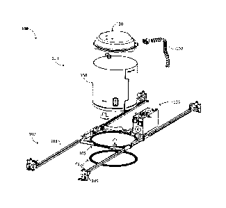
[0038] Figure 1 shows an exploded view of an example luminaire 101 in
accordance with certain example embodiments. In one or more embodiments, one
or
more of the components shown in Figure 1 may be omitted, added, repeated,
and/or
substituted. Accordingly, embodiments of luminaires with example housings
and/or
related components should not be considered limited to the specific
arrangements of
components shown in Figure 1.
[0039] Referring to Figure 1, the luminaire 101 can include a housing 129
(which
can include, for example, a housing body 150 (sometimes called a can 150) and
a housing
top 130 (sometimes called a can top 130), a housing 150 (sometimes called a
can 150)),
flexible conduit 102, a frame 105, a junction box 103, a sealing member 1370,
and an
optional mounting feature 107. The optional mounting feature 107 can have any
features
and configurations to mount the rest of the luminaire 101 to one or more
structures (e.g.,
a wall, a ceiling, a piece of wood, a post). In this example, the mounting
feature 107
includes one or more hanger bars 108 and one or more hanger bar fasteners 109.
An
optional hanger bar fastener 109 can be mechanically coupled to each end of a
hanger bar
8
CA 02848297 2014-04-04
=
108 and can be mechanically coupled to a surface (e.g., a wall, a piece of
wood, a metal
frame, a concrete pillar) that is used to support the luminaire 101.
[0040] The housing body 150 of the housing can have any shape and/or size
appropriate for mechanically coupling to the frame 105. The housing body 150
can be
used to enclose one or more of a number of components of the luminaire 101.
Such
components can include, but are not limited to, a power source (e.g., a
driver, a ballast),
one or more light sources, a fan, and a lens. The housing body 150 can be
mechanically
coupled to the housing top 130, disposed at the top and/or at some other
location on the
housing body 150, to provide access within the housing body 150. The example
housing
body 150 and housing top 130 are described in more detail below with respect
to Figures
2A-4B.
[0041] In certain example embodiments, the flexible conduit 102 is coupled
to
both the junction box 103 and a portion of the housing 129. For example, in
this case, the
flexible conduit 102 is mechanically coupled to the housing top 130 of the
housing 129.
The flexible conduit 102 can be any component that is capable of containing
(hosting)
one or more electrical wires. In such a case, the flexible conduit 102 can
protect the one
or more electrical wires disposed therein from elements (e.g., dirt, moisture)
and/or
physical harm (e.g., pinching). In some cases, some or all of the flexible
conduit 102 is
rigid rather than flexible.
[0042] Such electrical wires can be used to provide power and/or control
between
the junction box 103 and the housing 129. Thus, at least part of the
electrical wire is
disposed in the junction box 103, part is disposed in the flexible conduit
102, and part is
disposed in the housing 129. As the name implies, the flexible conduit 102 is
bendable
and movable so that one or more components of the luminaire 101, including the
flexible
conduit 102, can be repositioned or otherwise moved without becoming decoupled
from
the junction box 103 and the housing 129. The junction box 103 can include one
or more
of a number of components, including but not limited to terminal blocks,
electrical
devices, and other electrical wires.
[0043] In certain example embodiments, the frame 105 is formed from a
single
piece. Alternatively, the frame 105 can be an assembly of two or more frame
pieces that
are shaped and sized to couple to each other to form the frame 105. The frame
105 can
9
CA 02848297 2014-04-04
= =
be mechanically coupled to one or more hanger bars 108 (or other mounting
features 107)
so that the hanger bars 108 extend from the frame 105 in one or more
directions. In
addition, or in the alternative, the frame 105 can be directly coupled to a
mounting
surface to support the luminaire 101. The frame 105 can have any shape and/or
size
suitable for the housing 129.
[0044] In certain example embodiments, one or more portions
(e.g., sides) of the
frame 105 can include one or more complementary coupling features that receive
and/or
otherwise couple to one or more coupling features of the junction box 103. The
sealing
member 1370, described in more detail below with respect to Figures 13A-13F,
can be
used to reduce or eliminate external elements (e.g., moisture, dust) from
entering inside
the housing 129. In addition, or in the alternative, the sealing member 1370
can be used
to seal a gap between the frame 105 and the housing 129. Further, as shown in
Figures
15A and 15B, the sealing member 1370 can reduce or prevent air flow between an
external surface (e.g., a ceiling) and the outside of the -frame 105 and/or
housing 129.
= [0045] Figures 2A-2C show various views of an example housing body
150 of a
luminaire in accordance with certain example embodiments. Figure 2A shows a
perspective view of the housing body 150 as a flat sheet. Figures 2B and 2C
show
perspective views of the housing body 150 in its normal form. In one or more
embodiments, one or more of the components shown in Figures 2A-2C may be
omitted,
added, repeated, and/or substituted. Accordingly, embodiments of a housing
body should
not be considered limited to the specific arrangements of components shown in
Figures
2A-2C.
[0046] Referring to Figures 1-2C, in certain example
embodiments, the housing
body 150 has at least one wall 159 that forms a cavity 198. As described, one
or more
components of the luminaire 101 can be disposed inside the cavity 198 of the
housing
body 150. The housing body 150 can include a top end 166, a bottom end 167, a
left end
151, and a right end 161. The housing body 150 can include one or more of a
number of
coupling features that can be used to mechanically couple to another portion
of the
housing body 150 and/or to another component of the luminaire 101. The wall
159 of the
housing body 150 can be bendable, such that the housing body 150 can be formed
into
one or more of a number of shapes. In certain example embodiments, at least
one portion
CA 02848297 2014-04-04
=
of the housing body 150 can be pre-formed to exemplify the shape (e.g.,
curvature) of the
housing body 150.
[0047] For example, as shown in Figures 2A-2C, the housing body
150 can
include one or more coupling features 152 (also called housing body coupling
features
152) and/or one or more coupling features 162 (also called housing body
coupling
features 162). Each coupling feature 152 and each coupling feature 162 can be
used,
directly or indirectly, to mechanically couple one part of the housing body
150 to another
part of the housing body 150. In this example, the coupling feature 152 and
the coupling
features 162 can be used to mechanically couple the left end 151 and the right
end 161 of
the housing body 150 to each other.
[0048] In this case, as shown in Figures 2A-2C, the coupling
feature 152 is a tab
disposed on the distal end of the left end 151. The coupling feature 152 can
be positioned
between (e.g., substantially centered between) two left end portions 153. The
coupling
feature 152 can be vertically offset relative to the left end portions 153. In
this example,
= the left end portions 153 are substantially planar with the wall 159 of
the housing body
150, while the coupling feature 152 is recessed lower (when viewing the
housing body
150 from the outer surface) relative to the left end portions 153. Similarly,
the coupling
features 162 in this case is a tab disposed on the distal end of the right end
161. The
coupling features 162 can be positioned on either side of a right end portion
163. The
coupling features 162 can be vertically offset relative to the right end
portion 163. In this
example, the right end portion 163 is substantially planar with the wall 159
of the housing
body 150, while the coupling features 162 are recessed lower (when viewing the
housing
body 150 from the outer surface) relative to the right end portion 163.
[0049] In certain example embodiments, the length and width of
the coupling
feature 152 is substantially the same as the length and width of the right end
portion 163.
Similarly, the length and width of the coupling features 162 can be
substantially the same
as the length and width of the left end portion 153. The coupling feature 152
can be
configured to engage (mechanically couple to) the right end portion 163 (also
called a
complementary coupling feature), and the coupling features 162 can be
configured to
engage the left end portions 153 (also called a complementary coupling
features), which
can create an air-tight seal therebetween. For the coupling feature 152 to
engage the right
11
CA 02848297 2014-04-04
= =
end portion 163 and for the coupling features 162 to engage the left end
portions 152, the
housing body 150 can be bent or otherwise shaped so that these features align
with each
other.
[0050] The amount that the coupling feature 152 is vertically offset
relative to the
left end portions 153 can be substantially the same as the amount that the
coupling
features 162 are vertically offset relative to the right end portion 163. In
such a case,
when the coupling feature 152 mechanically couples to the right end portion
163 and
when the coupling features 162 mechanically couple to the left end portions
153, a tight
seal is formed along the height of the housing body 150.
[0051] In such a case, one or more of the coupling feature 152, the left
end
portions 153, the coupling features 162, and/or the right end portions 163 can
include one
or more other coupling feature to help secure the left end 151 of the housing
body 150 to
the right end 161. For example, as shown in Figures 2A-2C, the coupling
feature 152 and
the right end portion 163 can each have an aperture that traverses
therethrough. In such a
case, the aperture 154 in the coupling feature 152 and the aperture 164 in the
right end
portion 163 can have a shape and size substantially the same to each other.
Further, the
position of the aperture 154 on the coupling feature 152 and the position of
the aperture
164 in the right end portion 163 can be such that the aperture 154 and the
aperture 164
are substantially aligned with each other when the coupling feature 152 is
mechanically
coupled to the right end portion 163. Another coupling device (e.g., a screw,
a rivet) can
be traverse the aperture 154 and the aperture 164 to secure the coupling
feature 152 to the
right end portion 163.
[0052] As another example, at least one of the coupling features 162 can
have a
coupling feature 165 (e.g., a recessed area, a protrusion) disposed thereon.
Similarly, at
least one of the left end portions 153 can have a coupling feature (e.g., a
protrusion, a
recessed area) (hidden from view in this case) that complements the coupling
feature 165
and is aligned with the coupling feature 165 when the coupling features 162
are
mechanically coupled to the left end portions 153.
[0053] In certain example embodiments, the thickness of the various
coupling
features (e.g., coupling feature 152, coupling feature 162) along the left end
151 and the
right end 161 have a thickness that is substantially the same as the thickness
of the wall
12
CA 02848297 2014-04-04
=
159. In such a case, one or more coupling features (in this example, coupling
feature
152) along the left end 151 can be recessed relative to the one or more other
coupling
features (in this example, coupling features 153) along the left end 151.
Similarly, one or
more coupling features (in this example, coupling feature 162) along the right
end 161
can be recessed relative to the one or more other coupling features (in this
example,
coupling features 163) along the right end 161. In this way, when the coupling
feature
152 and the coupling feature 162 are mechanically coupled to each other and
when the
coupling features 153 and the coupling features 163 are mechanically coupled
to each
other, the outer surface of the housing body 150 can be substantially uniform
around its
perimeter.
[0054] The housing body 150 can also include one or more coupling features
for
mechanically coupling the housing body 150 to another component of the
luminaire 101.
In such cases, an air-tight seal can be formed between the coupling features.
For
example, as shown in Figures 2A-2C, the housing body 150 can include a
coupling
feature 157 (also called a sealing member coupling feature 157) for
mechanically
coupling the sealing member 1370 to the housing body 150, which can create an
air-tight
seal therebetween. In this case, the coupling feature 157 is a protrusion that
extends
some or all of the outer perimeter of the wall 159 and is disposed toward the
bottom end
167. More information about the sealing member 1370 is described below with
respect
to Figures 13A-14C.
[0055] In certain example embodiments, the coupling feature 157 separates a
lower wall 169 from the wall 159. The lower wall 169 can have can have one or
more
aligning features 168 disposed along its outer edge. Such aligning features
168 in this
case are a recess in the outer edge of the lower wall 169. The aligning
features 168 can
be used, for example, to align the luminaire 101 to one or more adjacent
luminaires.
[0056] As another example, one or more coupling features 156 (also called
housing top coupling features 156) for mechanically coupling the housing top
130 to the
housing body 150, which can create an air-tight seal therebetween. In this
case, the
coupling features 156 is a protrusion that extends some or all of the outer
perimeter of the
wall 159 and is disposed toward the top end 166. Additional details about the
coupling
features 156 are provided below with respect to Figures 3A and 3B
13
CA 02848297 2014-04-04
[0057] As yet another example, one or more coupling features 155 (also
called
thermal protector case coupling features 155) can be disposed on the wall 159
of the
housing body 150, which can create an air-tight seal therebetween. In this
example, as
shown in Figures 2A-2C, the coupling features 155 can be a number of apertures
can
traverse the thickness of the wall 159. The coupling features 155 can be used
to receive
and couple to a thermal protector case (e.g., protector case 680) or some
other component
of the luminaire 101. Examples of a thermal protector case is described below
with
respect to Figures 5A-6.
[0058] As still another example, one or more coupling features 158 (also
called
frame coupling features 158) can be disposed on the wall 159 of the housing
body 150.
In this example, as shown in Figures 2A-2C, the coupling features 158 can be a
number
of shaped protrusions each having one or more apertures (e.g., holes, slots)
disposed
therein, where each aperture traverses the thickness of the wall 159
(including the
protrusion of the coupling feature 158). The coupling features 158 can be used
to receive
and couple to a portion of the frame 105, which can create an air-tight seal
therebetween.
[0059] Figures 3A and 3B show various side views of a housing 129 that
includes
the housing body 150 of Figures 2A-2C in accordance with certain example
embodiments. In one or more embodiments, one or more of the components shown
in
Figures 3A and 3B may be omitted, added, repeated, and/or substituted.
Accordingly,
embodiments of a housing should not be considered limited to the specific
arrangements
of components shown in Figures 3A and 3B.
[0060] Referring to Figures 1-3B, the housing top 130 can be mechanically
coupled to the housing body 150 at the top end 166 of the housing body 150,
which can
create an air-tight seal therebetween. The housing top 130 can include a top
portion 131,
a side portion 136, and an intermediate portion 132 positioned between the top
portion
131 and the side portion 136. In certain example embodiments, as least part of
the
intermediate portion 132 includes an interface portion 139 that includes a
side wall 133
and a bottom wall 138. The side wall 133 can have an aperture 134 traversing
therethrough. The bottom wall 138 can include one or more coupling features
135
disposed thereon. In such a case, the bottom wall 138 and the side wall 133 of
the
14
CA 02848297 2014-04-04
interface portion 139 can interrupt at least a portion of the top portion 131
and/or the
intermediate portion 132.
[0061] The aperture 134 in the side wall 133 of the interface portion 139
can have
a shape and size suitable for receiving one or more of a number of electrical
wires, as
well as the flexible conduit 102 into which the electrical wires can be
disposed. The
aperture 134 can also have a shape and size suitable to receive a portion of a
flex
connector (e.g., flex connector 710, flex connector 810), as described below
with respect
to Figures 7A-9B.
[0062] In this case, the coupling features 135 (also called flex connector
coupling
features 135) disposed on the bottom wall 138 of the interface portion 139 can
be
configured to mechanically couple to a flex connector, which can create an air-
tight seal
therebetween. Such coupling features 135 can be tabs enclosed on two sides,
tabs
enclosed on three sides, one or more notches, one or more apertures, or any
other suitable
features for receiving corresponding coupling features of a flex connector.
The shape and
size of the size portion 136 can be substantially the same as, or slightly
larger than, the
shape and size of the top end 166 of the hosing body 150.
[0063] In certain example embodiments, the side portion 136 can include one
or
more coupling features 137 (also called housing body coupling features 137)
for
mechanically coupling the housing top 130 to the housing body 150, which can
create an
air-tight seal therebetween. Specifically, the coupling features 137 can
mechanically
couple to the coupling features 156 of the housing body 150. The coupling
features 137
can include, but are not limited to, a detent, a protrusion, a clip, and a
recess. In this
example, the coupling features 137 can be protrusions that slide over the
protrusions
formed by the coupling features 156. Alternatively, the coupling features 137
can be
recesses that receive the protrusion formed by the coupling features 156.
[0064] When the coupling features 137 of the housing top 130 mechanically
couple to the coupling features 156 of the housing body 150, an air-tight seal
can be
formed between the housing top 130 and the housing body 150. In addition to
meeting
ASTM E283-04 and/or an equivalent thereof, the air-tight seal formed between
the
housing top 130 and the housing body 150 can prevent one or more elements
(e.g.,
moisture, dust) from outside the housing 129 from entering the cavity 198 of
the housing
CA 02848297 2014-04-04
129. In certain example embodiments, one or more additional components (e.g.,
a
sealing member, such as an o-ring or a gasket) can be positioned between the
top end 166
of the housing body 150 and one or more portions (e.g., the side portion 136)
of the
housing top 130. In addition, or in the alternative, some form of sealant
(e.g., caulk) can
be applied to the junction between the housing top 130 and the housing body
150 by a
user to form the seal between the housing top 130 and the housing body 150.
[0065] Figures 4A and 4B show various views of another housing top 430 in
accordance with certain example embodiments. Specifically, Figure 4A shows a
top
perspective view of the housing top 430, and Figure 4B shows a cross sectional
side view
of the a portion of the housing top 430 that includes the coupling features
455. The
housing top 430 in this case is substantially the same as the housing top 130
of Figures
3A and 3B, except as described below. Specifically, the coupling features 455
are
disposed on the top portion 431 rather than on the wall 159 of the housing
body 150, as
shown in Figures 2A-2C.
[0066] The coupling features 455 can be the same as, or different than, the
coupling features 155 of Figures 2A-2C. In any case, the coupling features
455, like the
coupling features 155 of Figures 2A-2C, are configured to mechanically couple
to a
thermal protector case, which can create an air-tight seal therebetween. The
coupling
features 455 of Figures 4A and 4B can be recessed tabs enclosed on two sides,
recessed
tabs enclosed on three sides, one or more notches, one or more apertures, or
any other
suitable features for receiving corresponding coupling features of a thermal
protector
case.
[0067] Further, the coupling features 137 of the housing top 130 shown in
Figures
3A and 3B above are not part of the side portion 436 of the housing top 430 of
Figures
4A and 4B. Instead, the equivalent of the coupling features 137 can be
disposed on the
inner surface of the side portion 436, hidden from view in Figures 4A and 4B.
Alternatively, the side portion 436 of the housing top 430 can be without any
coupling
features.
[0068] The coupling features 435 and/or the coupling feature 455 can be
disposed
in one or more other locations on the housing top 430. In addition, or in the
alternative,
coupling features 435 and/or the coupling feature 455 can be disposed on one
or more
16
CA 02848297 2014-04-04
=
other components of the luminaire, including but not limited to a socket
assembly, a
floating connector to a light engine (e.g., light-emitting diode driver), and
a light engine.
Thus, the flex connector 102 can be mechanically coupled to the housing 429
(e.g., the
housing top 430), a socket assembly, a floating connector to a light engine
(e.g., light-
emitting diode driver), a light engine, and/or some other component of the
luminaire.
[0069] As generally described above with respect to coupling
features described
herein, the coupling features 435 and/or the coupling feature 455 can be
disposed on the
housing top 430 can be part of a single piece with the housing top 430 (as
from a mold or
stamping the coupling features from the housing top 430), housing body 450,
and/or
other component of the luminaire. Alternatively, the coupling features 435
and/or the
coupling feature 455 can be separate pieces that are mechanically coupled to
the housing
top 430, housing body 450, and/or other component of the luminaire using one
or more of
a number of methods, including but not limited to welding, epoxy, fastening
devices, and
compression fittings. The coupling features can be recessed (as with the
coupling
features 455 shown in Figures 4A and 4B) or protruding (as with the coupling
features
435) relative to a surface of a component (e.g., the housing top 430, the
housing body
= 450).
[0070] Figures 5A and 5B show various views of a thermal
protector case 580
coupled to a portion of the housing top 430 of Figures 4A and 4B in accordance
with
certain example embodiments. Specifically, Figure 5A shows a bottom
perspective view
of the thermal protector case 580 and the housing top 430, and Figure 4B shows
a cross
sectional side view of the a portion of the housing top 430 that includes the
coupling
features 455. In one or more embodiments, one or more of the components shown
in
Figures 5A and 5B may be omitted, added, repeated, and/or substituted.
Accordingly,
embodiments of a housing top and thermal protector case should not be
considered
limited to the specific arrangements of components shown in Figures 5A and 5B.
[0071] Referring to Figures 1-5B, the thermal protector case
580 can be used to
encase a thermally-sensitive device. Examples of such a thermally-sensitive
device can
include, but are not limited to, a sensor and a thermocouple. In certain
example
embodiments, the thermal protector case 580 can include one or more coupling
features
586 (also called housing top coupling features 586 or, if the coupling
features 455 are
17
CA 02848297 2014-04-04
disposed on the housing body, as in Figures 2A-2C, the housing body coupling
features)
the that mechanically couple to corresponding coupling features (e.g.,
coupling features
455) of another component (e.g., the housing top 430) of the luminaire. When
this
occurs, the thermal protector case 580 can be mechanically coupled to that
component of
the luminaire, which can create an air-tight seal therebetween. In this
example, the
coupling features 586 of the thermal protector case 580 can be tabs that each
can
mechanically couple to the coupling features 455 of the housing top 430. In
the example
shown in Figures 5A and 5B, each of the coupling features 586 of the thermal
protector
case 580 is disposed within each of the coupling features 455 of the housing
top 430.
[0072] In certain example embodiments, the thermal protector
case 580 can also
include a body 582 and one or more sides (e.g., side 584, side 585, side 588)
that extend
from an outer portion of the body 582. One or more of the coupling features
586 of the
thermal protector case 580 can be coupled to a side of the thermal protector
case 580.
For example, a coupling feature 586 can be disposed on an outer edge of side
584, and
= another coupling feature 586 can be disposed on an outer edge of side
585. A side (e.g.,
side 584, side 585, side 588) of the thermal protector case 580 can be
disposed at an
angle (e.g., 90 ) relative to the body 582. Similarly, a coupling feature 586
can be
disposed at an angle (e.g., 90 ) relative to the corresponding side.
[0073] To allow the coupling features 586 of the thermal
protector case 580 to be
disposed within each of the corresponding coupling features 455 of the housing
top 430,
one or more portions of the thermal protector case 580 can be flexible and/or
movable
(e.g., extendable, slidable). For example, one or more of the coupling
features 586 can be
retractable. As another example, the body 582 and/or sides (e.g., side 584,
side 585) of
the thermal protector case 580 can be flexible. When viewing the housing top
430 from
the outside when the thermal protector case 580 is mechanically coupled to the
housing
top 430, at least part of the coupling features 586 of the thermal protector
case 580 can be
seen through the coupling features 455 in the housing top 430.
[0074] In certain example embodiments, when the thermal
protector case 580 is
mechanically coupled to the housing top 430, some or all of the thermal
protector case
580 creates an air-tight (or nearly air-tight) seal with the housing top 430.
As a result,
there may be no sealing device (e.g., gasket, silicone) needed to prevent
dust, moisture,
18
CA 02848297 2014-04-04
and other contaminants from entering the housing 429. In addition to meeting
ASTM
E283-04 and/or an equivalent thereof, a sealing member, a user-applied
sealant, and/or
some other device can be used to create the air-tight seal between the thermal
protector
case 580 and the housing top 430. The air-tight seal created between the
thermal
protector case 580 and the housing top 430 can prevent air from within the
housing 429
from escaping.
[0075] Figure 6 shows a perspective view of a thermal protector case 680
coupled
to the housing body 650 in accordance with certain example embodiments. In
this
example, as shown in Figure 6, the coupling features 655 that complement the
coupling
features 686 of the thermal protector case 680 are disposed on the wall 659 of
the housing
body 650 (as opposed to, or in addition to, the thermal top). As a result, the
thermal
protector case 680 is disposed inside the housing 629 when the coupling
features 686 of
the thermal protector case 680 are mechanically coupled to the coupling
features 655,
which can create an air-tight seal therebetween. In the orientation shown in
Figure 6, the
wall 688 of the thermal protector case 680 has a curved distal portion that
abuts against
the bottom wall 638 of the housing top 630.
[0076] Figures 7A-7C show various views of a flex connector 710 in
accordance
with certain example embodiments. Specifically, Figure 7A shows a top
perspective
view of the flex connector 710. Figure 7B shows a side perspective view of the
flex
connector 710. Figure 7C shows a top view of the flex connector 710 in a flat
form. In
one or more embodiments, one or more of the components shown in Figures 7A-7C
may
be omitted, added, repeated, and/or substituted. Accordingly, embodiments of a
flex
connector should not be considered limited to the specific arrangements of
components
shown in Figures 7A-7C.
[0077] Referring to Figures 1-7C, in certain example embodiments, the flex
connector 710 can include one or more coupling features 718 (also called
housing top
coupling features 718) that allow the flex connector 710 to mechanically
couple to the
coupling features (e.g., coupling features 435) of a housing top (e.g.,
housing top 430).
In this example, coupling features 718 of the flex connector 710 are tabs that
can be
disposed within the coupling features of a housing top. The coupling features
718 can be
disposed on each side of the body 712 of the flex connector 710. A coupling
feature 718
19
CA 02848297 2014-04-04
can include one or more elements (e.g., a downward protruding element (as
shown in
Figures 7A-7C), an upward protruding element) to help secure the coupling
feature 718
to a complementary coupling feature (e.g., coupling feature 455).
[0078] Each coupling feature 718 can be disposed on (e.g., mechanically
coupled
to, a portion of) a bottom 717 of the flex connector 710. In this case, each
coupling
feature 718 is an extension of the bottom 717 and are disposed on a distal end
of the
bottom 717. Each bottom 717 can be adjacent to a side 716 of the flex
connector 710,
and each side 716 can be adjacent to a top 712 of the flex connector 710. In
some cases,
as shown in Figures 7A-7C, an apex 711 of the flex connector 710 can be
disposed
between adjacent tops 712.
[0079] To allow the coupling features 718 of the flex connector 710 to be
disposed within each of the complementary coupling features (e.g., coupling
feature 455
of the housing top 430), one or more portions of the flex connector 710 can be
flexible
and/or movable (e.g., extendable, slidable). For example, one or more of the
coupling
features 718 can be retractable. As another example, the flex connector 710
can be
flexible, so that the sides 716 and/or the tops 712 of the flex connector 710
can be
pinched inward momentarily by a user.
[0080] In certain example embodiments, the flex connector 710 can have one
or
more of a number of coupling features 719 (also called flex connector coupling
features
719) disposed in the sides 716 and/or the tops 712 of the flex connector 710.
In this
example, the coupling features 719 are tabs. The coupling features 719 can be
used to
secure at least part of a component (e.g., flexible conduit 102) of the
luminaire. Such
coupling features 719 can be fixed or adjustable, and can extend inward or in
some other
suitable direction relative to the sides 716 and/or the tops 712 of the flex
connector 710.
In this example, the coupling features 719 are stamped out of the sides 716
and/or the
tops 712 of the flex connector 710, leaving apertures 707 that traverse
therethrough. In
such a case, the coupling features 719 can be bent into position so that each
coupling
feature 719 is pointed inward toward the cavity 715 formed by the sides 716
and the tops
712 of the flex connector 710. A coupling features 719 can have different
shapes and/or
or sizes relative to the shapes and sizes of the other coupling features 719
of the flex
connector 710.
CA 02848297 2014-04-04
[0081] In certain example embodiments, the flex connector 710
includes an
aperture 708, through which one or more components (e.g., wires, cables) of
the
luminaire can extend. The aperture 708 can be bounded by a collar 714 disposed
on an
end 713 of the flex connector 710. The end 713 of the flex connector 710 can
be set at an
angle relative to the bottom 717 of the flex connector 710 so as to be
substantially the
same as the angle between the bottom wall (e.g., bottom wall 138) and the side
wall (e.g.,
side wall 133) of the interface portion (e.g., interface portion 139) of the
housing top
(e.g., housing top 130). In other words, the angle between the end 713 and the
bottom
717 of the flex connector 710 allows the end 713 to abut substantially flush
against the
side wall of the interface portion of the housing top, and also allows the
bottom 717 to
abut substantially flush against the bottom wall of the interface portion of
the housing
top.
[0082] The collar 714 can have a size, shape, and other
dimensions (e.g.,
thickness, width) that allow the collar 714 of the flex connector 710 to fit
within the
aperture (e.g., aperture 634) in a housing top (e.g., housing top 630). When
the collar
714 is disposed within the aperture in the housing top, an air-tight seal can
be formed
= therebetween. The collar 714 can have a rolled (smooth) edge to reduce
the possibility of
a wire or cable of getting cut or pinched. A seal can be formed between the
collar 714 of
the flex connector 710 and the housing top 630.
[0083] As Figure 7C shows, the flex connector 710 can be
created by cutting,
pressing, stamping, bending, and/or otherwise manipulating a continuous sheet
of some
material (e.g., metal, plastic, rubber). Some apertures (e.g., aperture 708,
apertures 707)
of the flex connector 710 can be stamped out of the sheet. Multiple flex
connectors 710
can be created from a single sheet.
[0084] Figures 8A and 8B show various views of another flex
connector 810 in
accordance with certain example embodiments. Specifically, Figure 8A shows a
top
perspective view of the flex connector 810. Figure 8B shows a bottom
perspective view
of the flex connector 810. The flex connector 810 of Figures 8A and 8B is
substantially
the same as the flex connector 710 of Figures 7A-7C, except that the shape and
orientation of the coupling features 818 of the flex connector 810 are
different than the
shape and orientation of the coupling features 718 of the flex connector 710.
21
CA 02848297 2014-04-04
[0085] Similarly, Figures 9A and 9B show various views of yet another flex
connector 910 in accordance with certain example embodiments. Specifically,
Figure 9A
shows a top perspective view of the flex connector 910. Figure 9B shows a
bottom view
of the flex connector 910. The flex connector 910 of Figures 9A and 9B is
substantially
the same as the flex connector 710 of Figures 7A-7C and the flex connector 810
of
Figures 8A and 8B, except as described below.
[0086] The flex connector 910 does not have an apex. In other words, there
is
one continuous top 912 that covers the middle portion of the flex connector
910. Further,
the apertures 907 in the top 912 and sides 916 of the flex connector of
Figures 9A and 9B
are shaped in substantial rectangles, as opposed to the corresponding
apertures of the flex
connector 710 and the flex connector 810, which are irregularly shaped. In
addition, the
flex connector 910 includes one or more coupling features 991 (also called
flex connector
coupling features 991) disposed on the outer edge of the end 913 of the flex
connector
910. Each coupling feature 991 can be movable relative to the end 913. In this
example,
each coupling feature 991 can be positioned over a complementary coupling
feature
(hidden from view by the coupling feature 991) (e.g., a protrusion, a slot)
disposed in one
or both sides 916 so that the coupling feature 991 can be mechanically coupled
to a side
916. Alternatively, the coupling feature 991 can be disposed on a side 916 and
movable
relative to the side 916. In such a case, the coupling feature 991 can be
positioned over a
complementary coupling feature disposed on the end 913.
[0087] Figures 10A-10F show various views of a subsystem 1000 of the
luminaire that includes a flex connector 1010 coupled to a housing top 1030 in
accordance with certain example embodiments. Figure 10A shows a top
perspective
view of the subsystem 1000. Figure 10B shows a top view of the subsystem 1000.
Figure 10C shows a rear view of the subsystem 1000. Figure 10D shows a bottom
view
of the subsystem 1000. Figures 10E and 1017 each show a cross-sectional
perspective
view of the subsystem 1000. In one or more embodiments, one or more of the
components shown in Figures 10A-10F may be omitted, added, repeated, and/or
substituted. Accordingly, embodiments of a flex connector coupled to a housing
top
should not be considered limited to the specific arrangements of components
shown in
Figures 10A-10F.
22
CA 02848297 2014-04-04
[0088] Referring to Figures 1-10F, when viewing the housing top 1030 from
the
inside when the flex connector 1010 is mechanically coupled to the housing top
1030, at
least part of the coupling features 1018 of the flex connector 1010 can be
seen through
the apertures in the housing top 1030 created by the coupling features 1035 of
the bottom
wall 1038. The collar 1014 of the flex connector 1010 can be disposed within
the
aperture 1034 that traverses the side wall 1033 of the interface portion 1039
of the
housing top 1030. In such a case, the collar 1014 of the flex connector 1010
can be
mechanically coupled to the side wall 1033 of the interface portion 1039 of
the housing
top 1030.
[0089] In certain example embodiments, when the collar 1014 of the flex
connector 1010 is mechanically coupled to the side wall 1033 of the interface
portion
1039 of the housing top 1030, some or all of the collar 1014 and/or the end
1013 of the
flex connector 1010 creates an air-tight (or nearly air-tight) seal with the
housing top
1030. As a result, there may be no sealing member (e.g., gasket, silicone, o-
ring) needed
to meet the requirements under ASTM E283-04 (and/or an equivalent thereof),
and/or to
prevent dust, moisture, and/or other contaminants from entering the housing
1029 where
the flex connector 1010 is mechanically coupled to the housing top 1030. In
addition, or
in the alternative, the air-tight seal created between the flex connector 1010
and the
housing top 1030 can prevent air from within the housing 1029 from escaping.
The air-
tight seal can be formed where the collar 1013 couples to the side wall 1033
of the
interface portion 1039 of the housing top 1030 and/or where the coupling
features 1018
of the flex connector 1010 couple to the coupling features 1035 of the housing
top 1030.
[0090] The position and/or orientation of the coupling features 1018 of the
flex
connector 1010, the coupling features 1035 of the housing top 1030, the collar
1013 of
the flex connector 1010, and the aperture 1034 in the side wall 1033 of the
housing top
1030 can be such that the end 1013 of the flex connector 1010 abuts against
the side wall
1033 and the bottom 1017 of the flex connector 1010 abuts against the bottom
wall 1038
of the housing top 1030 when the coupling features 1035 are engaged with the
coupling
features 1018 and when the collar 1014 is engaged with the side wall 1033 at
the aperture
1034.
23
CA 02848297 2014-04-04
[0091] Figures 11A-11C show various views of a subsystem 1100 that includes
a
flex connector 1110 coupled to a flexible conduit 1102 in accordance with
certain
example embodiments. Figure 11A shows a perspective view of the subsystem
1100.
Figure 11B shows a top view of the subsystem 1100. Figure 11C shows a bottom
perspective view of the subsystem 1100. In one or more embodiments, one or
more of
the components shown in Figures 11A-11C may be omitted, added, repeated,
and/or
substituted. Accordingly, embodiments of a flex connector coupled to a
flexible conduit
should not be considered limited to the specific arrangements of components
shown in
Figures 11A-11C.
[0092] Referring to Figures 1-11C, the various coupling features 1119 of
the flex
connector 1110 can be positioned (e.g., bent) in such a way in the cavity 1115
of the flex
connector 1110 so as to secure the flexible conduit 1102. For example, the
coupling
features 1119 disposed in the sides 1116 of the flex connector 1110 can be
bent inward to
abut against the bottom portion of the flexible conduit 1102, while the
coupling features
1119 disposed in the tops 1112 of the flex connector 1110 can be bent inward
to abut
against the top portion of the flexible conduit 1102. Further, the distal end
of the flexible
conduit 1102 can abut against the inner surface of the end 1113 of the flex
connector
1110.
[0093] The coupling features 1119 can be moved into position after the
flexible
conduit 1102 is disposed within the cavity 1115 of the flex connector 1110. In
such a
case, flex connector 1110 can be used to house any of a number of sizes of
flexible
conduits 1102. The coupling features 1119 can be spaced in such a way as to
allow the
flexible conduit 1102 to fit between the coupling features 1119 within the
cavity 1115. In
addition, or in the alternative, one or more of the coupling features 1119 can
be
positioned within the cavity 1115 in such a way as to substantially match the
pitch of the
flexible conduit 1102. In such a case, the coupling features 1119 can act as
threads so
that the flexible conduit 1102 can be rotated further into or out of the
cavity 1115 of the
flex connector 1110 using the coupling features 1119.
[0094] Figures 12A-12C show various perspective views of a subsystem 1200
that includes a housing body 1250 coupled to a frame 1205 in accordance with
certain
example embodiments. Specifically, Figure 12A shows a coupling feature 1206 of
the
24
CA 02848297 2014-04-04
frame 1205 that is initially engaged with the coupling feature 1258 of the
housing body
1250 by a fastening device 1292 (e.g., a screw). Figures 12B and 12C shows the
coupling feature 1206 of the frame 1205 fully engaged with the coupling
feature 1258 of
the housing body 1250 by the fastening device 1292. In one or more
embodiments, one
or more of the components shown in Figures 12A-12C may be omitted, added,
repeated,
and/or substituted. Accordingly, embodiments of a housing body coupled to a
frame
should not be considered limited to the specific arrangements of components
shown in
Figures 12A-12C.
[0095] Referring to Figures 1-12C, the fastening device 1292
can be directed
from within the cavity 1298 of the housing body 1250, through an aperture in
the wall
1259 of the housing body 1250, and through an aperture in the coupling feature
1206
(also called a housing coupling feature) of the frame 1205. As the fastening
device 1292
is driven further outward, the coupling feature 1206 of the frame 1205 is
drawn toward
the coupling feature 1258 disposed on the wall 1259 of the housing body 1250.
Eventually, substantially all of the coupling feature 1206 abuts against
substantially all of
the coupling feature 1258 disposed on the wall 1259 of the housing body 1250.
The
= frame 1205 can have more than one coupling feature 1206.
[0096] As described above, each coupling feature 1258 disposed
on the housing
body 1250 can be a protrusion from the wall 1259 of the housing body 1250. As
the
fastening device 1292 draws the housing coupling feature 1206 of the frame
1205 toward
the coupling feature 1258, the coupling feature 1258 can become deformed so
that an air-
tight seal can be formed between the housing coupling feature 1206 of the
frame 1205
and the coupling feature 1258. In so doing, any portions of the aperture (in
the case of a
slot) in the coupling feature not occupied by the fastening device 1292 is
covered by the
housing coupling feature 1206. Further, because the coupling feature 1258 can
be
deformed to form an air-tight seal with the housing coupling feature 1206, the
cylindrical
shape of the wall 1259 and the rest of the housing body 1250 can remain
substantially
unchanged (little or no deformity), which allows the other coupling features
disposed on
the housing body 1250 to maintain an air-tight seal with the corresponding
coupling
features to which they couple.
CA 02848297 2014-04-04
[0097] In certain example embodiments, when the coupling feature 1206 of
the
frame 1205 is mechanically coupled to the coupling feature 1258 disposed on
the wall
1259 of the housing body 1250, some or all of the coupling feature 1206 of the
frame
1205 creates an air-tight (or nearly air-tight) seal with the coupling feature
1258 disposed
on the wall 1259 of the housing body 1250. As a result, there may be no
sealing member
(e.g., gasket, silicone, o-ring) needed to prevent dust, moisture, and/or
other contaminants
from entering the housing 1229 where the coupling feature 1206 is mechanically
coupled
to the coupling feature 1258. In addition, or in the alternative, the air-
tight seal created
between the coupling feature 1206 and the coupling feature 1258 can prevent
air from
within the housing 1229 from escaping.
[0098] Figures 13A-13F show various views of a subsystem 1300 that includes
a
sealing member 1370 integrated with a frame 1305 in accordance with certain
example
embodiments. Figure 13A shows a top view of the subsystem 1300. Figure 13B
shows a
cross-sectional side view of the sealing member 1370. Figures 13C and 13D show
cross-
sectional side views of a portion of the subsystem 1300. Figure 13E shows a
top
perspective view of the subsystem 1300 without the sealing member 1370. Figure
13F
shows a top perspective view of the subsystem 1300 with the sealing member
1370. In
one or more embodiments, one or more of the components shown in Figures 13A-
13F
may be omitted, added, repeated, and/or substituted. Accordingly, embodiments
of a
sealing member coupled to a frame should not be considered limited to the
specific
arrangements of components shown in Figures 13A-13F.
[0099] Referring to Figures 1-13F, the sealing member 1370 can be a
flexible
material that helps keep some or all of a number of elements (e.g., dust,
moisture) from
entering the cavity 1398 of the housing 1329. The sealing member 1370 can be
made of
one or more of a number of materials, including but not limited to an
elastomeric, rubber,
plastic, and paper. The frame 1305 can have one or more walls that form a
channel 1349
into which some or all of the sealing member 1370 can be disposed. For
example, as
shown in Figures 13A-13F, the frame 1305 can include a an outer wall 1395, a
right side
wall 1394, a top wall 1393, and a left side wall 1396 that is disposed over
some or all of
the perimeter of the frame and form a cavity 1397 therebetween. The shape and
size of
the cavity 1397 formed by the various walls (particularly the left side wall
1396) of the
26
CA 02848297 2014-04-04
frame 1305 can be substantially the same as (or slightly larger than) the
shape and size of
the cavity formed by the bottom end of the housing body.
[00100] In its natural state, the sealing member 1370 can appear
as shown in
Figure 13B. In this example, the sealing member 1370 can have a rounded top
1371
having an extension 1373 on each side of the top 1371, a base 1372, and one or
more
sides 1374. In this case, there are two sides 1374 that form, along with the
top 1371 and
the base 1372, a cavity 1375. The cavity 1375 can have a width, formed by the
sides
1374. Each extension 1373 can extend laterally beyond the sides 1374, and the
width of
the base 1372 can also be larger than the width of the cavity 1375. Further,
as shown in
Figure 3B, the width of the base 1372 can be larger than the width of the top
1371,
including the extensions 1373.
[00101] In certain example embodiments, the boundaries of the
channel 1349 in
which the sealing member 1370 is disposed can change along its length. For
example, as
shown in Figure 13C, the channel 1349 can be defined by the right side wall
1394, the
= top wall 1393, and the left side wall 1396. In such a case, the width of
the channel 1349
can be less than the width of the top 1371 with the extensions 1373. As a
result, the
= extensions 1373 are forced inward, causing the top 1371 and the sides
1374 to be
compressed and deformed. This compression and deformation of the top 1371 and
the
sides 1374 can cause one or more seals to form between the sealing member 1370
and the
right side wall 1394, the top wall 1393, and/or the left side wall 1396. In
addition, with
an upward force applied to the sealing member 1370 and/or a downward force
applied to
the frame 1305 can create a seal between the base 1372 of the sealing member
1370 and
the outer wall 1395.
[00102] As another example of how the boundaries of the channel
1349 in which
the sealing member 1370 is disposed can change along its length, as shown in
Figure
13D, the channel 1349 can be defined by the top wall 1393 and the left side
wall 1396,
without the right side wall 1394. As a result, one the left extension 1373 of
the sealing
member 1370 is forced inward, causing part of the top 1371 and one of the
sides 1374 to
be compressed and deformed. This compression and deformation of the top 1371
and the
left side 1374 can create one or more seals with the right side wall 1394
and/or the top
wall 1393. In addition, with an upward force applied to the sealing member
1370 and/or
27
CA 02848297 2014-04-04
a downward force applied to the frame 1305 can create a seal between the base
1372 of
the sealing member 1370 and the outer wall 1395.
[00103] In certain example embodiments, the sealing member 1370 can form a
continuous loop. In other words, the sealing member 1370 can have not ends.
Alternatively, the sealing member 1370 can be have two ends that abut against
each other
when the sealing member 1370 is disposed in the channel 1349 of the frame
1305. In
such a case, the sealing member 1370 can be cut to a length that is
substantially the same
as the length of the channel 1349 of the frame 1305 in which the sealing
member 1370 is
disposed. Figures 13E and 13F show the coupling feature 1306 of the frame
1305. Here,
the aperture 1327 through which a fastening device (e.g., fastening device
1292 described
above with respect to Figures 12A-12C) can be disposed.
[00104] The frame 1305 can include one or more of a number of protruding
members 1389 (e.g., tabs) that are used to secure the vertical position of the
sealing
member 1370 relative to the frame 1305. For example, protruding members 1389
can be
disposed adjacent to and on either side of an optional aperture 1348 formed in
the frame
1305 by the coupling feature 1306. In addition, or in the alternative, the
protruding
members 1389 can be disposed at one or more other locations along the channel
1349, as
shown in Figure 13A, regardless of whether one or more optional apertures 1348
in the
frame 1305 exist. The protruding members 1389 can extend inward toward the
channel
1349 to the extent that the protruding members 1389 are disposed between one
of the
extensions 1373 of the top 1371, the base 1372, and one of the sides 1374 of
the sealing
member 1370. In certain example embodiments, the protruding members 1389 abut
against one or more of the extensions 1373 of the top 1371, the base 1372, and
one of the
sides 1374 of the sealing member 1370.
[00105] Figures 14A-14C show various views of a portion of a luminaire 1400
that
includes a sealing member 1470 integrated with a housing 1429 and a frame 1405
in
accordance with certain example embodiments. Figure 14A shows a bottom
exploded
view of the portion of the luminaire 1400. Figure 14B shows a bottom view of
the
portion of the luminaire 1400. Figure 14C shows a side perspective cross-
sectional view
of the portion of the luminaire 1400. In one or more embodiments, one or more
of the
components shown in Figures 14A-14C may be omitted, added, repeated, and/or
28
CA 02848297 2014-04-04
substituted. Accordingly, embodiments of a luminaire should not be considered
limited
to the specific arrangements of components shown in Figures 14A-14C.
[00106] The luminaire 1400 of Figures 14A-14C is substantially
similar to the
subsystem 1300 of Figures 13A-13F, except that the luminaire 1400 includes the
housing
1429. Referring to Figures 1-14C, the coupling feature 1457 disposed on the
housing
body 1450 can be disposed below, and abut against, the base 1472 of the
sealing member
1470. In such a case, the coupling feature 1457 can help (in addition to the
protruding
members 1489 of the frame 1405) to secure the sealing member 1470 relative to
the
frame 1405 and the housing 1429. In addition, the coupling feature 1457 of the
housing
body 1450 can apply a compressive force against the base 1472 of the sealing
member
1470, forming a seal between the coupling feature 1457 and the base 1472.
[00107] Figures 15A and 15B shows various views of a lighting
system 1599 that
includes a luminaire 1501 installed in a ceiling 1579 in accordance with
certain example
embodiments. Specifically, Figure 15A shows a cross-sectional side view of the
lighting
system 1599, and Figure 15B shows a detailed cross sectional side view of the
components adjacent to the sealing member 1570. In this case, the sealing
member 1570
= can reduce or prevent air flow between an external surface 1579 (e.g., a
ceiling) and the
outside of the frame 1505 and/or housing 1529. In addition, or in the
alternative, the
sealing member 1570 can be used to seal a gap 1578 between the frame 1505 and
the
external surface 1579 and/or between the housing 1529 (e.g., the lower wall
1569) and
the external surface 1579.
[00108] Certain example embodiments provide a number of
benefits. Examples of
such benefits include, but are not limited to, use of fewer materials,
simplified
installation, simplified inspection, simplified maintenance, installation of a
luminaire in
relatively small spaces, and reduced cost. Example housings and related
components
described herein also allow for increased flexibility for manufacturing,
installing, and/or
maintaining a luminaire.
1001091 Although embodiments described herein are made with
reference to
example embodiments, it should be appreciated by those skilled in the art that
various
modifications are well within the scope and spirit of this disclosure. Those
skilled in the
art will appreciate that the example embodiments described herein are not
limited to any
29
CA 02848297 2014-04-04
specifically discussed application and that the embodiments described herein
are
illustrative and not restrictive. From the description of the example
embodiments,
equivalents of the elements shown therein will suggest themselves to those
skilled in the
art, and ways of constructing other embodiments using the present disclosure
will suggest
themselves to practitioners of the art. Therefore, the scope of the example
embodiments
is not limited herein.