Note: Descriptions are shown in the official language in which they were submitted.
81778198
METHODS AND APPARATUS TO EXCHANGE A FLUID
OF AN IMPLANTABLE DEVICE
CROSS-REFERENCE TO RELATED APPLICATIONS
[0001] This application claims priority of the following co-pending
U.S.
Provisional Patent Applications : (1) U.S. Provisional Application Serial No.
61/535,900, titled, "Fluid Exchange Apparatus and Methods," filed on September
16, 2011; and (2) U.S. Provisional Application Serial No. 61/595,604, titled,
"Fluid
Exchange Apparatus and Methods," filed on February 6, 2012.
BACKGROUND
[0002] The present disclosure is generally directed to methods and
apparatus to exchange a fluid of an implantable device.
[0003] Implantable devices can be used to provide a therapeutic agent
to
one or more portions of a body of a patient. The implantable device may have a
chamber for storing the therapeutic agent, and the agent can be released into
the
patient to provide a therapeutic benefit. After an amount of time, the amount
of
fluid release can be less than ideal, and the fluid of the implantable device
may
be replaced, refilled, or exchanged to provide additional amounts of
therapeutic
agent to extend the therapy.
[0004] Work in relation to embodiments of the present disclosure
indicates
that the prior methods and apparatus to place a fluid in a device implanted in
the
body can be less than ideal in at least some instances. For example, the
amount
of therapeutic fluid placed in an implanted therapeutic device with injection
can
be less than ideal in at least some instances. The therapeutic fluid placed in
the
implantable device may mix with a fluid already present in the implanatble
device, such that the amount of therapeutic fluid placed in the implantable
devices can be less than ideal in at least some instances. Also, mixing of the
implantable device fluid with the therapeutic fluid during exchange can
provide a
less than ideal sample of the fluid from the implantable device in at least
some
1
CA 2848385 2018-12-06
CA 02848385 2014-03-10
WO 2013/040247
PCT/US2012/055216
instances. At least some of the prior injections may at least partially damage
the
implantable device, for example with repeated injection of a needle through a
septum. Further, as the implantable device may be small, the amount of
pressure within a chamber of the implantable device may substantially exceed
atmospheric pressure in order to provide a clinically acceptable amount of
time to
place the therapeutic fluid in the implanted device. In at least some
instances the
seal between the injector apparatus and implantable therapeutic device may be
absent or inadequate and the exchanged fluids may leak from one or more of the
injector apparatus or the implantable device in at least some instances.
[0005] Refilling devices implanted in the eye may present additional
challenges in at least some instances. At least some of the prior devices
implanted in the eye can be small to decrease interference with vision, and
the
refill port of such devices can be small and the eye can move rapidly in at
least
some instances. Alignment of the injection apparatus with the refill port of
the
implanted device can be more difficult than would be ideal in at least some
instances.
[0006] Work in relation to embodiments suggests that at least some prior
injector apparatus may be reused among patients, for example needles, and it
may be helpful to limit reuse of the injector apparatus.
[0007] At least some of the prior methods and apparatus to diagnose a
patient have been less than ideal in at least some respects. In at least some
instances, the eye disease may have progressed more than would be ideal.
Although tissue can be removed from the patient with a biopsy or vitreous
humor
removed with a vitreal tap, such procedures can be more invasive than would be
ideal. It would be helpful to provide methods and apparatus to obtain a sample
from a patient that is less invasive than prior methods and apparatus.
SUMMARY
[0008] In light of the above, it would be desirable to provide improved
treatments for the eye and improved methods and apparatus to place therapeutic
fluids in a device implanted in the eye. These treatments and methods and
apparatus would decrease at least some of the deficiencies of the prior art,
and
2
CA 02848385 2014-03-10
WO 2013/040247
PCT/1JS2012/055216
would provide improved replacement and sampling of a fluid of a device
implanted within the body, improved ease of alignment, improved exchange
efficiency, little or no leakage resulting from pressure of the injection, and
a
clinically acceptable exchange time.
[0009] Embodiments disclosed herein provide improved methods and
apparatus to treat a patient having a device implanted in the body. The
apparatus may comprise an exchange apparatus having an elongate structure
capable of extending into the implantable device when implanted, and the
elongate structure may comprise an opening to place a therapeutic fluid in the
implanted device and one or more openings to receive an implantable device
fluid from the implantable device. The implantable device may comprise a lock,
and the exchange apparatus may comprise a key, so as to limit access to
appropriate apparatus and formulations appropriate for the implantable device.
The implantable device fluid may comprise air, or a liquid such as saline or a
fluid
comprising a component of the patient. The elongate structure of the exchange
apparatus may comprise a needle and a sheath, in which the sheath extends
over a proximal portion of the needle so that the needle and the sheath can be
advanced through a penetrable barrier and into a reservoir of the implantable
device. The sheath extending over at least a portion of the needle can
maintain
integrity of the penetrable barrier, and can provide an outflow path having a
low
resistance to flow so that the fluid within the implantable device can be
displaced
with decreased pressure. The outflow path can extend from the one or more
openings to a receiver container configured to receive the fluid of the
implantable
device. The implantable device may comprise a porous structure to release
therapeutic agent for an extended time. The porous structure may comprise a
resistance to fluid flow greater than the resistance to flow of the outflow
path from
the one or more openings to the receiver container, so that the fluid of the
implantable device can be displaced to the receiver container and flow through
the porous structure inhibited. The exchange apparatus may comprise a receiver
container to receive a sample of the implantable device fluid when the
therapeutic fluid is placed in the implantable device. In many embodiments,
the
3
CA 02848385 2014-03-10
WO 2013/040247
PCMJS2012/055216
exchange apparatus is configured to separate at least a portion of the
implantable device fluid from the therapeutic fluid. The separation of at
least a
portion of the implantable device fluid from the therapeutic fluid can provide
a
sample of the implantable device fluid useful for analysis and may increase
the
amount of therapeutic fluid placed in the implantable device.
[0010] The one or more openings may comprise a plurality of openings to
receive the implantable device fluid. In many embodiments, an injector
apparatus comprises an elongate structure having a plurality of openings
positionable near a penetrable barrier of the implantable device so as to
receive
fluid of the implantable device and increase exchange efficiency and decrease
refill pressure. The elongate structure may comprise a distal tip to penetrate
tissue and the penetrable barrier, and a distal opening near the tip to
release
therapeutic fluid into the implantable chamber. In many embodiments the distal
tip, the distal opening, and the plurality of openings are separated from a
stop
that engages a tissue of the patient and limits penetration depth such that
the
distal opening and the plurality of openings are located along an axis of the
implantable device so as to increase efficiency of the exchange. A tapered
portion of the elongate structure can extend between the distal opening and
the
plurality of openings so as to stretch a penetrable barrier when the elongate
structure is advanced. The plurality of openings can be located away from the
tapered portion along a proximal portion so as to maintain integrity of the
penetrable barrier and so that leakage can be inhibited. The penetrable
barrier
can be used repeatedly with pressure for subsequent fluid exchange which can
extend the lifetime of the device implanted in the eye. The proximal portion
of
the elongate structure may comprise an extension without openings extending
from the stop to the plurality of openings so as to inhibit leakage through
the
penetrable barrier and place the plurality of openings away from a proximal
side
of the penetrable barrier. The extension without openings may extend from the
stop to the plurality of openings a distance corresponding substantially to a
thickness of the penetrable barrier, such that at least one of the plurality
of
openings is placed near an inner surface of the penetrable barrier so as to
4
CA 02848385 2014-03-10
WO 2013/040247
PCMJS2012/055216
receive fluid near the surface of the penetrable barrier and increase an
efficiency
of the exchange. The plurality of openings can be distributed along an axis of
the
elongate structure and may be distributed circumferentially around the
elongate
structure so as to receive fluid from a plurality of axial and circumferential
locations of the reservoir chamber of the implantable device.
[0011] The fluid initially within the implantable device may comprise a
density less than a therapeutic fluid, and the distal tip and plurality of
openings
can be configured to at least partially separate the fluid injected through
the distal
tip from the fluid received through the plurality of openings. The distal
opening
may be placed below the plurality of openings so as to increase separation and
the efficiency of the exchange. The distal opening can be placed below the
plurality of openings with a distance from the stop shorter than a length of
the
implantable device. The distance from the distal opening to the stop may
correspond to a length of the reservoir chamber of the implantable device so
as
to position the distal tip having the opening near a distally located porous
structure of the implantable device. In many embodiments the distance from the
distal opening to the stop can be no more than about half the distance of the
reservoir chamber of the implant so as to facilitate alignment and provide
high
exchange efficiency with the distal opening placed below the proximal
plurality of
openings.
[0012] In many embodiments, the exchange apparatus comprises one or
more structures to separate at least a portion of the implantable device fluid
from
the therapeutic fluid. The one or more structures may comprise a valve, fluid
separator, a separator fluid or combinations thereof. The separator fluid may
comprise a fluid miscible with the therapeutic fluid and the implantable
device
fluid, or a fluid immiscible with the therapeutic fluid and the implantable
device
fluid such as an immiscible fluid comprising one or more of an oil, a
hydrophobic
liquid, a gas, or air. The separator fluid can be contained in the fluid
separator to
inhibit mixing of the implantable device fluid with the therapeutic fluid. The
valve
may be coupled to a first receiver container and a second receiver container
such that a first portion of the implantable device fluid can be placed in the
first
CA 02848385 2014-03-10
WO 2013/040247
PCT/1JS2012/055216
container without substantial amounts of therapeutic fluid. A second portion
of
the implantable device fluid mixed with the placed therapeutic fluid can be
placed
in the second receiver container to inhibit mixing of the therapeutic fluid
with the
sample contained in the first container. The fluid separator may comprise a
structure configured to contain the separator fluid between the implantable
device fluid and the therapeutic fluid to inhibit mixing.
[0013] While the elongate structure can be configured in many ways, in
many embodiments the elongate structure comprises a needle extending from
the proximal stop to the distal tip and a sheath placed over the needle to
provide
the plurality of openings and the tapered intermediate portion. The sheath may
comprise a distal portion to engage the needle and an increased cross
sectional
size to provide the taper. In many embodiments the sheath located over the
needle provides one or more channels coupled to the plurality of opening to
receive the fluid from the implantable device. The one or more channels may
extend proximally from the plurality of openings to a container to receive the
fluid
from the implantable device.
[0014] The exchange apparatus can be coupled to an injector in many
ways and may comprise an injector, such as a syringe. In many embodiments
the exchange apparatus comprises a connector to couple to a syringe. The
connector may comprise a known standard connector, such as a Luer connector,
or may comprise a custom connector, such as a keyed connector, to inhibit
inappropriate access to the implantable device. The connector may comprise a
lock and key mechanism. The connector of the implantable device may
comprise a lock and the connector of the syringe may comprise a key to access
the exchange apparatus. Alternatively, the injector can be integrated with the
exchange apparatus, and the injector may comprise an amount of therapeutic
agent to inject into the implantable device.
[0015] In many embodiments, the receiver container comprises one or
more channels that vent to atmospheric pressure such that a gas within the
receiver container can be displaced with fluid comprising liquid from the
implantable device. The receiver container may comprise a porous structure
that
6
CA 02848385 2014-03-10
WO 2013/040247
PCT/1JS2012/055216
readily allows passage of the gas from the receiver container with a low
resistance to flow and substantially inhibits passage of the liquid from the
implantable device chamber with a substantially greater resistance to flow.
The
receiver container may comprise a volume to inhibit re-use of the exchange
apparatus, such that the injector apparatus can be a single-use device. The
volume of the receiver container may be no more than about twice a volume of
the reservoir chamber of the implantable device, for example.
[0016] The container of the exchange apparatus can be configured to
receive a sample from the implantable device container, and to provide access
to
the fluid stored in the receiver container. The fluid from the receiver
container can
be removed from the receiver container for analysis to determine the health of
the eye of the patient. The receiver container may comprise a penetrable
barrier
to access the fluid sample within the receiver container with a needle. The
receiver container may be separated from the exchange apparatus to provide the
sample from the container. Alternatively or in combination, the receiver
container
may be pressurized to displace the sample fluid from the reservoir container.
[0017] In many embodiments, a sample container can be coupled to the
receiver container so as to receive the implantable device fluid from the
receiver
container. The exchange apparatus may comprise an elongate structure having
one or more openings to receive the implantable device fluid, and the
implantable
device fluid can be displaced from the receiver container so as to pass
through
the one or more openings and into the sample container. The implantable device
fluid can be displaced from the receiver container in many ways. A pressure
source or a vacuum source such as a syringe can be coupled to the one or more
openings to urge the implantable device fluid from the receiver container to
the
sample container. The implantable device fluid can be urged, for example
drawn, into the sample container with aspiration from the vacuum source
comprising the syringe. Alternatively or in combination, the implantable
device
fluid can be urged, for example pushed, with pressurization of the receiver
container, for example from a pressure source comprising a syringe. A channel
may extend from the receiver container to an opening that vents to atmospheric
7
81778198
pressure during exchange, and the opening can be coupled to the syringe with
pressurization subsequent to exchange, such that the channel and receiver
container
can be pressurized so as to urge fluid from the receiver container through the
one or
more openings. The receiver container and sample container may be placed in a
centrifuge to urge implantable device fluid through the one or more openings
onto an
inner surface of the sample container. The sample container may comprise a
penetrable barrier such as a septum, and the elongate structure may be
advanced to
place the one or more openings within a chamber of the sample container such
that
the implantable device fluid can be displaced from the receiver container.
[0018] Additional aspects of the present disclosure are recited in the
claims
below, and can provide additional summary in accordance with embodiments. It
is
contemplated that the embodiments as described herein and recited in the
claims
may be combined in many ways, and any one or more of the elements recited in
the
claims can be combined together in accordance with embodiments of the present
disclosure and teachings as described herein.
[0018a] According to one aspect of the present invention, there is provided
a
system for injecting a therapeutic agent into an ocular implant, the ocular
implant
being at least partially implanted in an eye, the system comprising: a
connector
configured to reversibly couple to a syringe; a needle coupled to the
connector and
having a wall defining an injection lumen configured for injecting a
therapeutic agent
into the ocular implant through an opening from the injection lumen, the
therapeutic
agent having a first fluid density; a sheath positioned over the needle, the
sheath
having a wall defining an outlet lumen between an inner diameter of the wall
of the
sheath and an outer diameter of the wall of the needle, the wall of the sheath
having
a wall thickness and at least one opening extending through the wall thickness
into
the outlet lumen, the outlet lumen providing a pathway through which pre-
existing
liquid in the ocular implant exits the ocular implant as therapeutic agent is
injected
into the ocular implant through the needle, the pre-existing liquid having a
second
fluid density; and a receiver chamber coupled to the sheath and fluidly
coupled to the
outlet lumen of the sheath, the receiver chamber configured to receive the pre-
existing liquid that exits the ocular implant via the at least one opening
extending
8
CA 2848385 2018-12-06
81778198
through the wall thickness of the sheath, wherein the injection lumen is in a
fixed
position relative to the outlet lumen, such that the opening from the
injection lumen is
positioned distal to a distal end of the sheath, and wherein injection of the
therapeutic
agent into the ocular implant upon application of positive pressure by the
syringe via
the injection lumen displaces, with at least partial separation from the
injected
therapeutic agent, the pre-existing liquid in the ocular implant into the
receiver
chamber via the at least one opening of the sheath.
[0018b] According to another aspect of the present invention, there is
provided
an exchange device to inject a therapeutic agent into an ocular implant that
is at least
partially implanted in an eye, the exchange device comprising: a connector
configured
to reversibly couple to a syringe; a needle having a proximal end region
coupled to
the connector, the needle defining an injection lumen configured for injecting
a
therapeutic agent into the ocular implant through a distal opening of the
needle; a
receiver container coupled to the connector; and an outer sheath coupled to a
distal
end region of the receiver container, the outer sheath comprising: a wall
defining an
outlet lumen between an inner diameter of the wall and an outer diameter of
the
needle, the outlet lumen in fluid communication with the receiver container; a
distal
tip; and a plurality of openings extending through the wall of the outer
sheath into the
outlet lumen, wherein the receiver container is coupled to the connector such
that the
outer sheath is positioned around at least a portion of the needle and the
distal
opening of the needle is positioned distal to the distal tip of the outer
sheath, and
wherein application of positive pressure through the injection lumen by the
syringe
during injection of the therapeutic agent into the ocular implant displaces,
with at least
partial separation from the injected therapeutic agent, pre-existing liquid in
the ocular
implant into the receiver container via the outlet lumen.
BRIEF DESCRIPTION OF THE DRAWINGS
[0019] Figure 1 shows an eye suitable for incorporation of the therapeutic
device;
[0020] Figure 2 shows a therapeutic device implanted under the
conjunctiva and extending through the sclera to release a therapeutic agent
into vitreous
humor of the eye so as to treat the retina of the eye;
[0021] Figure 3A shows an embodiment of a therapeutic device
8a
CA 2848385 2019-07-10
81778198
comprising a container having a penetrable barrier disposed on a first end, a
porous
structure disposed on a second end to release therapeutic agent for an
extended time;
[0022] Figure 3B shows an embodiment of a porous structure comprising a
plurality of channels extending substantially straight through a disk;
[0023] Figure 4 shows an embodiment of an apparatus to exchange fluid of a
device implanted in a an eye;
8b
CA 2848385 2019-07-10
CA 02848385 2014-03-10
WO 2013/040247
PCMJS2012/055216
[0024] Figure 5 shows an embodiment of an apparatus to exchange fluid
coupled to an implanted device;
[0025] Figure 6 shows an embodiment of an elongate structure of the
apparatus to exchange fluid as in Figure 5;
[0026] Figure 7 shows a cross-sectional view of an embodiment of an
elongate structure of the apparatus exchange fluid comprising a sheath over a
needle;
[0027] Figure 7A shows an embodiment of an exchange apparatus
comprising a locking connector to couple to a syringe;
[0028] Figure 7B shows an embodiment of an elongate structure and
receiver container of the exchange apparatus of Figure 7A;
[0029] Figure 7C shows embodiments of sheaths suitable for combination
with the exchange apparatus of Figures 7A and 7B;
[0030] Figure 7D shows an embodiment of a sheath opening having a
beveled channel surface to inhibit degradation of the penetrable barrier;
[0031] Figure 7E shows an embodiment of a sheath opening having a
rounded channel surface and edge to inhibit degradation of the penetrable
barrier;
[0032] Figure 7F shows an embodiment of schematic illustration of the
pressure drops across the porous structure and the one or more channels
extending from the plurality of openings to the receiver container;
[0033] Figure 8A shows a cross-sectional view of an embodiment of the
apparatus to exchange fluid as in Figures 5 and 6 coupled to a syringe;
[0034] Figure 8B shows an embodiment of an implantable therapeutic
device comprising a lock and an exchange apparatus comprising a key to the
lock;
[0035] Figure 8B1 shows an embodiment of a deflectable elongate
structure in an unloaded configuration prior to insertion in the lock of
Figure 8B;
[0036] Figure 8B2 shows an embodiment of a deflected elongate structure
in an unloaded configuration prior to insertion in the lock of Figure 8B;
9
CA 02848385 2014-03-10
WO 2013/040247
PCT/1JS2012/055216
[0037] Figure 8C1 shows an embodiment of an implantable therapeutic
device comprising a lock and an exchange apparatus comprising a rotatable key
to the lock;
[0038] Figure 8C2 shows an embodiment of an implantable therapeutic
device of Figure 801 in a locked configuration in which the elongate structure
extends through the open lock to access the reservoir chamber of the
implantable device;
[0039] Figure 8D1 shows an embodiment of an implantable therapeutic
device comprising a lock and an exchange apparatus comprising a slidable key
to the lock;
[0040] Figure 8D2 shows an embodiment of an implantable therapeutic
device of Figure 8D1 in a locked configuration in which the elongate structure
extends through the open lock to access the reservoir chamber of the
implantable device;
[0041] Figure 8E shows an embodiment of an implantable therapeutic
device comprising a lock and an exchange apparatus comprising an elongate
structure having engagement structures to open the lock;
[0042] Figure 9 shows an embodiment of a container to receive and store
the exchange apparatus;
[0043] Figure 10 shows an embodiment of an exchange apparatus having
a fluid sample within the receiver container;
[0044] Figure 11 shows an embodiment of the exchange apparatus having
the fluid sample placed partially within the storage container;
[0045] Figure 12 shows an embodiment of a cap of the storage container
placed over an outlet channel of the exchange apparatus to inhibit leakage;
[0046] Figure 13 shows an embodiment of an elongate structure of the
exchange apparatus placed within a soft penetrable material near the bottom of
the storage container and the cap placed over the container so as to seal the
exchange apparatus within the container;
[0047] Figure 14 shows an embodiment of an apparatus to remove the
sample fluid from the receiver container;
CA 02848385 2014-03-10
WO 2013/040247
PCT/1JS2012/055216
[0048] Figure 15 shows an embodiment of a cap placed on a connector to
couple a syringe to the exchange apparatus;
[0049] Figure 16 shows an embodiment of the exchange apparatus placed
within a receptacle to couple the receiver container with a syringe to
displace the
sample fluid from the receiver container into a sample container for analysis;
[0050] Figure 17 shows an embodiment of an exchange apparatus
coupled to a removable receiver container;
[0051] Figure 18 shows an embodiment of the exchange apparatus
coupled to an implanted device to exchange fluid and receive fluid from the
implanted device;
[0052] Figure 19 shows an embodiment of the exchange apparatus
removed from the implanted device and the receiver container detached from the
exchange apparatus;
[0053] Figure 20A shows an embodiment of components of a container to
remove a sample fluid from an exchange apparatus;
[0054] Figure 20B shows an embodiment of an exchange apparatus
placed in the container having components as in figure 20A;
[0055] Figures 20C and 20D show an embodiment of removal of a sample
fluid from an exchange apparatus with the sample fluid drawn into the
container
as in Figure 20B;
[0056] Figure 21 shows an embodiment of a method of removal from an
exchange apparatus with a removal container as in Figures 20A to 20D;
[0057] Figure 22 shows an embodiment of an exchange apparatus having
a receiver container comprising a penetrable barrier on a side port to remove
a
sample from the receiver container with a needle and syringe;
[0058] Figure 23A shows an embodiment of an exchange apparatus
having a receiver container coupled to a sample container and a syringe to
displace fluid from the receiver container;
[0059] Figure 23B shows the sample container of Figure 23A placed over
the plurality of openings of the exchange apparatus;
11
CA 02848385 2014-03-10
WO 2013/040247
PCMJS2012/055216
[0060] Figure 24A shows an embodiment of an exchange apparatus
having a receiver container coupled to a syringe with a sample container
placed
over openings of the exchange apparatus so as to remove a sample from the
receiver container;
[0061] Figure 24B shows an embodiment of the sample container of
Figure 24A placed over the plurality of openings of the exchange apparatus and
the opening to the injection needle;
[0062] Figure 25A shows an embodiment of an exchange apparatus
comprising a removable receiver container comprising a removable sheath
placed over a needle;
[0063] Figure 25B shows an embodiment of the removable container of
Figure 25A with a plug placed over the sheath and the needle removed;
[0064] Figure 250 shows an embodiment of the removable container of
Figures 25A and 25B with a plug placed over the sheath and a cap over the
removable receiver container;
[0065] Figures 26A, 26B, 260, 26D and 26E show an embodiment of a
centrifuge used to remove the fluid sample from the receiver container of the
exchange apparatus;
[0066] Figure 26F shows an embodiment comprising an exchange
apparatus placed in a sample container comprising a centrifuge tube;
[0067] Figure 25G shows an embodiment comprising an exchange
apparatus placed in a sample container comprising a centrifuge tube, in which
the centrifuge tube comprises a support comprising a narrow shoulder portion
of
the tube to hold the exchange apparatus;
[0068] Figure 26H shows an embodiment comprising an exchange
apparatus placed in a sample container comprising a centrifuge tube, in which
the centrifuge tube comprises a support comprising restricted portion to hold
the
exchange apparatus;
[0069] Figure 27A shows an embodiment of a collapsible fluid separator
for use with a therapeutic device;
12
CA 02848385 2014-03-10
WO 2013/040247
PCMJS2012/055216
[0070] Figure 27B shows an embodiment of a plunger comprising an
exchange needle and a shoulder suitable for use with the collapsible fluid
separator as in Figure 27A and a therapeutic device;
[0071] Figure 270 shows an embodiment of the collapsible fluid separator
as in Figure 27B placed within a reservoir chamber of a therapeutic device;
[0072] Figure 27D shows an embodiment of the plunger comprising the
exchange needle and the shoulder as in Figure 27B advanced into the access
port of the therapeutic device having the collapsible fluid separator placed
within
the reservoir chamber of the therapeutic device as in Figure 27C;
[0073] Figure 27E shows an embodiment of the collapsible fluid separator
advanced within the reservoir chamber of the therapeutic device as in Figure
27D
so as to displace the implantable device fluid from the reservoir chamber
through
the needle;
[0074] Figure 27F shows an embodiment of the collapsible fluid separator
advanced within the reservoir chamber to a location near the distal end of the
reservoir chamber so as to displace most of the implantable device fluid from
the
reservoir chamber through the needle;
[0075] Figure 27G shows an embodiment of the collapsible fluid separator
moved from the distal end of the reservoir chamber so as to place therapeutic
device fluid in the reservoir chamber;
[0076] Figure 27H shows an embodiment of the collapsible fluid separator
moved from the distal end of the reservoir chamber to the proximal end of the
reservoir chamber so as to fill substantially the reservoir chamber;
[0077] Figure 271 shows an embodiment of a substantially non-collapsible
fluid separator placed within a rigid walled container of a therapeutic device
having a substantially fixed cross sectional size;
[0078] Figure 28A shows an embodiment of an exchange apparatus
comprising a balloon supported on an elongate tubular member capable of
introduction into an implantable therapeutic device to exchange the
implantable
device fluid with a therapeutic fluid;
13
CA 02848385 2014-03-10
WO 2013/040247
PCMJS2012/055216
[0079] Figure 28B shows an embodiment of the balloon as in Figure 28A
inflated within the therapeutic device to displace the implantable device
fluid;
[0080] Figure 280 shows an embodiment of the balloon deflated within the
therapeutic device to provide space for the therapeutic fluid;
[0081] Figure 28D shows an embodiment of the balloon punctured within
the therapeutic device to release the therapeutic fluid from the balloon to
the
reservoir chamber of the therapeutic device;
[0082] Figure 29A shows an embodiment of a deflectable fluid separator
placed within an implantable therapeutic device;
[0083] Figure 29B shows an embodiment of the deflectable fluid separator
as in Figure 29A displaced to a second side of the reservoir chamber to remove
fluid from the second side of the reservoir chamber;
[0084] Figure 290 shows an embodiment of the deflectable fluid separator
as in Figure 29B displaced to a first side of the reservoir chamber with the
therapeutic fluid placed in the second side;
[0085] Figure 30A shows an embodiment of an exchange apparatus
comprising a valve to direct flow toward a second receiver container when a
sample of the implantable device fluid has been placed in a first receiver
container;
[0086] Figure 30B shows an embodiment of an exchange apparatus
having a valve comprising a porous structure to direct flow toward a second
receiver container when a sample of the implantable device fluid has been
placed in a first receiver container;
[0087] Figure 300 shows an embodiment of an exchange apparatus
having a float valve comprising a ball to direct flow toward a second receiver
container when a sample of the implantable device fluid has been placed in a
first
receiver container;
[0088] Figure 30D shows an embodiment of an exchange apparatus
having a float valve comprising a sliding annular structure to direct flow
toward a
second receiver container when a sample of the implantable device fluid has
been placed in a first receiver container;
14
CA 02848385 2014-03-10
WO 2013/040247
PCMJS2012/055216
[0089] Figure 30E shows an embodiment of an exchange apparatus
having a float valve comprising a flap to direct flow toward a second receiver
container when a sample of the implantable device fluid has been placed in a
first
receiver container;
[0090] Figure 31A1 shows an embodiment of an exchange apparatus
having a fluid separator comprising an internal channel sized to support the
implantable device fluid with a pocket of air;
[0091] Figure 31A2 shows an embodiment of the exchange apparatus of
Figure 31A1 having the implantable device fluid supported with a pocket of air
to
separate the implantable device fluid from the therapeutic fluid;
[0092] Figure 31B1 shows an embodiment of an exchange apparatus
having a fluid separator comprising an internal channel having a first portion
sized to support the implantable device fluid with a pocket of air and a
second
portion sized to pass air through the implantable device fluid;
[0093] Figure 3162 shows an embodiment of the exchange apparatus of
Figure 31B1 having the first portion supporting the implantable device fluid
contained in the second portion with the pocket of air within the first
portion;
[0094] Figure 31B3 shows an embodiment of the exchange apparatus of
Figures 31B1 and 31B2 having the first portion supporting the implantable
device
fluid with the pocket of air and therapeutic fluid;
[0095] Figure 31C shows an embodiment of an exchange apparatus
coupled to a syringe to inject a displacement fluid comprising air into a
therapeutic device to collect a sample of implantable device fluid;
[0096] Figure 32 shows an embodiment of an exchange apparatus
coupled to a syringe to draw therapeutic fluid into the implantable device
with
aspiration of the implantable device fluid into the syringe;
[0097] Figure 33 shows an embodiment of a curved needle of an
exchange apparatus to direct therapeutic fluid toward a wall of a container;
[0098] Figure 34 shows an embodiment of a covering on a porous
structure of a therapeutic device to inhibit bolus release when the
therapeutic
CA 02848385 2014-03-10
WO 2013/040247
PCT/1JS2012/055216
fluid is introduced and a needle of an exchange apparatus oriented toward the
covering;
[0099] Figure 35 shows an embodiment of a first exchange apparatus
coupled to a double barrel syringe to exchange a first exchange fluid with the
implantable device fluid, and a second exchange apparatus to exchange the
first
exchange fluid placed in the therapeutic device with a therapeutic fluid;
[00100] Figure 36 shows an embodiment of an experimental test apparatus;
[00101] Figure 37 shows experimental results obtained with the test
apparatus of Figure 36.
DETAILED DESCRIPTION
[00102] Embodiments of the present disclosure as described herein can be
combined in many ways to treat one or more diseases of a patient such as a
disease of the eye. The embodiments as described herein are well suited to
treat patients with a therapeutic agent for an extended time, such as may be
provided with a device that can be at least partially implanted into the eye.
Although specific reference is made to ophthalmic treatment of the eye, the
methods and apparatus to place a therapeutic fluid in implantable device can
be
used with many implantable devices and treatments of one or more of many
diseases, such as systemic medication to treat systemic disease, orthopedic
treatment to treat orthopedic disorders, or dental treatment, for example. The
exchange apparatus and methods as described herein are well suited for use
with many drug delivery devices, such as refillable diffusion based devices,
and
can be exceptionally well suited for diffusion devices having a porous drug
release structure configured for extended release in which the porous
structure
inhibits flow of fluid during exchange.
[00103] The exchange apparatus and methods as described herein are well
suited for diagnoses and treatment of the eye, for example with diagnosis and
treatment of the eye based on the implantable device fluid received with the
exchange apparatus with the fluid is injected. The implantable device can be
combined with one or more known methods of analysis of biomarkers, for
16
81778198
example commercially available beads and arrays to detect and measure
biomarkers. The methods and apparatus as described herein are well suited for
combination with analysis of samples. Examples of injector apparatus,
therapeutic
devices, valves and mechanisms to provide the bolus injection are described in
U.S. Pat. App. Ser. No. 12/696,678, filed on January 29, 2010, entitled
Posterior
Segment Drug Delivery", U.S. Pat. Publication No. 2010/0255061; and U.S. PCT
Pat. App.
No. PCT/US2011/046812, filed August 5, 2011, entitled Injector Apparatus and
Method for Drug Delivery", PCT Publication No. WO/2012/019136.
PCT Patent Application No. PCT/US2012/049654, filed
August 3, 2012 entitled "Small Molecule Delivery with Implantable Therapeutic
Device", PCT Publication No. WO/2013/022801, may also be relevant.
[00104] As used herein like numerals and/or letters denote like
elements in
the drawings and text as will be apparent to a person of ordinary skill in the
art.
[00105] Figure 1 shows an eye 10 suitable for incorporation of the
therapeutic device. The eye has a cornea 12 and a lens 22 configured to form
an image on the retina 26. The cornea extends to a limbus 14 of the eye, and
the limbus connects to a sclera 24 of the eye. A conjunctiva 16 of the eye is
disposed over the sclera 24. A Tenon's capsule 17 extends between the
conjunctiva 16 and the sclera 24. The lens can accommodate to focus on an
object seen by the patient. The eye has an iris 18 that may expand and
contract
in response to light
[00106] The eye also comprises a choroid 28 disposed between the sclera
24 and the retina 26. The retina comprises the macula 32. The eye comprises a
pars plena, which comprises an example of a region of the eye suitable for
placement and retention, for example anchoring, of the therapeutic device as
described herein. The pars plane region may comprise sclera 24 and
conjunctiva 16 disposed between the retina 26 and cornea 12. The therapeutic
device can be positioned so as to extend from the pars plena region into the
17
CA 2848385 2018-12-06
CA 02848385 2014-03-10
WO 2013/040247
PCT/1JS2012/055216
vitreous humor 30 to release the therapeutic agent. The therapeutic agent can
be released into the vitreous humor 30, such that the therapeutic agent
arrives at
the retina 26 and choroid 28 for therapeutic effect on the macula 32. The
vitreous humor of the eye 30 comprises a liquid disposed between the lens 22
and the retina 26. The vitreous humor 30 may comprise convection currents to
deliver the therapeutic agent to the macula 32.
[00107] Figure 2 shows a therapeutic device 100 implanted under the
conjunctiva 16 and extending through the sclera 24. Figure 3A shows an
exemplary embodiment of the therapeutic device 100. The device 100 is
configured to release a therapeutic agent 110 into vitreous humor 30 of the
eye
so as to treat the retina of the eye. The therapeutic device 100 may comprise
a retention structure 120 such as a smooth protrusion configured for placement
along the sclera 24 and under the conjunctiva 16, such that the conjunctiva 16
can cover and protect the therapeutic device 100. When the therapeutic agent
110 is inserted into the device 100, the conjunctiva 16 may be lifted away,
incised, or punctured with a needle to access the therapeutic device 100. The
eye 10 may comprise an insertion of the tendon of the superior rectus muscle
to
couple the sclera of the eye to the superior rectus muscle. The device 100 may
be positioned in many locations of the pars plana region, for example away
from
tendon and one or more of posterior to the tendon, anterior to the tendon,
under
the tendon, or with nasal or temporal placement of the therapeutic device.
[00108] While the implant can be positioned in the eye in many ways, work
in relation to embodiments suggests that placement in the pars plana region 25
can release therapeutic agent into the vitreous 30 to treat the retina 26, for
example therapeutic agent comprising an active ingredient composed of large
molecules.
[00109] Therapeutic agents 110 suitable for use with device 100 include
many therapeutic agents, for example as listed in Table 1A, herein below. The
therapeutic agent 110 of device 100 may comprise one or more of an active
ingredient of the therapeutic agent, such as a formulation of the therapeutic
agent, a commercially available formulation of the therapeutic agent, a
physician
18
CA 02848385 2014-03-10
WO 2013/040247
PCMJS2012/055216
prepared formulation of therapeutic agent, a pharmacist prepared formulation
of
the therapeutic agent, or a commercially available formulation of therapeutic
agent having an excipient. The therapeutic agent may be referred to with
generic
name or a trade name, for example as shown in Table 1A.
[00110] The therapeutic device 100 can be implanted in the eye to treat the
eye for as long as is helpful and beneficial to the patient. For example the
device
can be implanted for at least about 5 years, such as permanently for the life
of
the patient. Alternatively or in combination, the device can be removed when
no
longer helpful or beneficial for treatment of the patient.
[00111] The therapeutic agent 110 can be placed in the therapeutic device
100 in many ways. In many embodiments, a therapeutic fluid 260 (Figure 2)
comprising therapeutic agent 110 is exchanged with an implantable device fluid
262 contained within therapeutic device 100, as shown in figure 2. An exchange
apparatus 200 can be configured to place the therapeutic fluid 260 and to
receive
the implantable device fluid displaced from the implantable device when the
therapeutic fluid is placed.
[00112] With reference to Figure 2, an exemplary embodiment of the
exchange apparatus 200 comprises an elongate structure 201 that can be placed
substantially within the implantable device. The elongate structure 201
comprises an opening to place the therapeutic fluid in the reservoir chamber
of
the implantable device and one or more openings to receive the implantable
device fluid from the reservoir chamber. The exchange apparatus 200 may
comprise the therapeutic fluid 260 and the receiver container 250 to receive
fluid
262 of the implantable device. The therapeutic device 100 may comprise a
reservoir chamber to store an amount of the therapeutic agent 110. The
reservoir chamber may comprise a fluid 262 of the implantable device 100. The
fluid 262 of the implantable device can be displaced when the therapeutic
fluid
260 is injected, for example, and a receiver container 250 can be provided to
receive the implantable fluid 262 from the implantable device. The reservoir
chamber of the implantable device may comprise a substantially rigid walls and
a
substantially fixed volume, for example.
19
CA 02848385 2014-03-10
WO 2013/040247
PCMJS2012/055216
[00113] The exchange apparatus 200 can be configured in many ways, and
may be coupled to a syringe 300 with one or more of many connectors, such as
a Luer connector, a Luer-LokTM connector, for example. Alternatively or in
combination, the exchange apparatus may comprise syringe 300, for example.
The exchange apparatus 200 may comprise an elongate structure 201 to for
insertion into the reservoir chamber of the implantable device, and a stop 240
to
limit a depth of insertion of the elongate structure 201 into the reservoir
chamber
of the implantable device. The exchange apparatus 200 may comprise a
receiver container 250 to receive the implantable device fluid from the
reservoir
chamber of the implantable device, and the elongate structure may comprise a
plurality of openings coupled to the receiver container so as to receive the
fluid of
the implantable device through the plurality of openings when the fluid is
injected.
Alternatively, the therapeutic fluid may be drawn into the reservoir chamber
of the
implantable device with aspiration of the implantable device fluid into
chamber
310 of the syringe, such that the therapeutic fluid placed in chamber 250 can
be
drawn into the reservoir chamber of the implantable device, for example.
[00114] Figure 3A shows a therapeutic device 100 comprising a container
130 having a penetrable barrier 184 disposed on a first end, a porous
structure
150 disposed on a second end to release therapeutic agent for an extended
period, and a retention structure 120 comprising an extension protruding
outward
from the container to couple to the sclera and the conjunctiva. The container
130
may comprise an axis 100A. The inner surfaces of the container 130 may define
a reservoir chamber having a volume sized to provide therapeutic amounts of
the
therapeutic agent for the extended time. The extending protrusion of the
retention structure may comprise a diameter 120D. The retention structure may
comprise an indentation 1201 sized to receive the sclera.
[00115] The container may comprise a tubular barrier 160 that defines at
least a portion of the reservoir, and the container may comprise a width, for
example a diameter 134. The diameter 134 can be sized within a range, for
example within a range from about 0.5 to about 4 mm, for example within a
range
from about 1 to 3 mm and can be about 2 mm, for example. The container may
CA 02848385 2014-03-10
WO 2013/040247
PCMJS2012/055216
comprise a length 136 sized so as to extend from the conjunctive to the
vitreous
along axis 100A to release the therapeutic agent into the vitreous. The length
136 can be sized within a range, for example within a range from about 2 to
about 1 4 mm, for example within a range from about 4 to 10 mm and can be
about 7 mm, for example. The volume of the reservoir may be substantially
determined by an inner cross sectional area of the tubular structure and
distance
from the porous structure to the penetrable barrier. The retention structure
may
comprise an annular extension having a retention structure diameter greater
than
a diameter of the container. The retention structure may comprise an
indentation
configured to receive the sclera when the extension extends between the sclera
and the conjunctive. The penetrable barrier may comprise a septum disposed on
a proximal end of the container, in which the septum comprises a barrier that
can
be penetrated with a sharp object such as a needle for injection of the
therapeutic agent. The porous structure may comprise a cross sectional area
150A sized to release the therapeutic agent for the extended period.
[00116] The porous structure 150 may comprise a control release
mechanism. The porous structure 150 can be configured in many ways to
provide controlled sustained release, for example with a release rate index,
or a
size and number of openings, for example. The porous structure 150 may
comprise a first side 150S1coupled to the reservoir and a second side 150S2 to
couple to the vitreous. The first side may comprise a first area 150A1 and the
second side may comprise a second area 150A2. The porous structure may
comprise a thickness 105T. The porous structure many comprise a diameter
150D.
[00117] The porous structure 150 may comprise one or more of a release
control element, a release control mechanism, permeable membrane, a semi-
permeable membrane, a material having at least one hole disposed therein,
channels formed in a rigid material, straight channels, nano-channels, nano-
channels etched in a rigid material, laser drilled holes, laser etched nano-
channels, a capillary channel, a plurality of capillary channels, one or more
tortuous channels, sintered material, sintered rigid material, sintered glass,
21
81778198
sintered ceramic, sintered metal, tortuous micro-channels, sintered nano-
particles, an open cell foam or a hydrogel such as an open cell hydrogel.
Additional examples of porous structures are described in U.S. Pat. App. Ser.
No. 12/696,678, filed on January 29, 2010, entitled Posterior Segment Drug
Delivery", U.S. Pat. Publication No. 2010/0255061; and U.S. PCT Pat. App. No.
PCT/US2011/046812, filed August 5, 2011, entitled "Injector Apparatus and
Method for Drug Delivery", PCT Publication No. WO/2012/019136.
[00118] The volume of the reservoir chamber may comprise from about 5
ul. to about 2000 jiL of therapeutic agent, or for example from about 10 uL to
about 200 fiL of therapeutic agent. The reservoir may comprise an axial length
136C extending between the penetrable barrier 184 and the porous structure
150.
[00119] The therapeutic agent stored in the reservoir of the container
comprises at least one of a solid comprising the therapeutic agent, a solution
comprising the therapeutic agent, a suspension comprising the therapeutic
agent, particles comprising the therapeutic agent adsorbed thereon, or
particles
reversibly bound to the therapeutic agent. For example, reservoir may comprise
a suspension of a cortico-steroid such as triamcinolone acetonide to treat
inflammation of the retina. The reservoir may comprise a buffer and a
suspension of a therapeutic agent comprising solubility within a range from
about
1 ug/mL to about 100 ug/mL, such as from about 111g/mL to about 40 mg/mL.
For example, the therapeutic agent may comprise a suspension of triamcinolone
acetonide having a solubility of approximately 19 ug/mL in the buffer at 37 C
when implanted.
[00120] The release rate index may comprise many values, and the
release
rate index with the suspension may be somewhat higher than for a solution in
many embodiments, for example. The release rate index may be no more than
about 5, and can be no more than about 2.0, for example no more than about
1.5, and in many embodiments may be no more than about 1.2, so as to release
22
CA 2848385 2018-12-06
CA 02848385 2014-03-10
WO 2013/040247
PCMJS2012/055216
the therapeutic agent with therapeutic amounts for the extended time. The
release rate index can be at about 0.01, for example.
[00121] The therapeutic device, including for example, the retention
structure and the porous structure, may be sized to pass through a lumen of a
catheter.
[00122] The porous structure may comprise a needle stop that limits
penetration of the needle. The porous structure may comprise a plurality of
channels configured for the extended release of the therapeutic agent. The
porous structure may comprise a rigid sintered material having characteristics
suitable for the sustained release of the material.
[00123] Figure 3B shows a porous structure comprising a plurality of
substantially straight channels 150SC extending substantially straight through
a
disk. The channels 150SC can extend from a first side 150S1 to a second side
150S2 a distance comprising thickness 150T of the porous structure. Each of
the channels comprises a cross-sectional dimension across, for example a
diameter, and a corresponding area across the cross section. The combined
cross-sectional area of the plurality of channels, the thickness 150T, the
diffusion
coefficient of the therapeutic agent, the concentration of therapeutic agent
within
the reservoir chamber and the volume of the reservoir chamber determine
substantially the release rate profile of the therapeutic agent. The size and
number of the plurality of channels 1505C and thickness of the porous
structure
can be configured so as to provide the release rate profile.
[00124] The porous structure 150 may comprise the control release
mechanism having one or more straight channels 150SC through which material
(e.g., fluid that contains therapeutic agent) can pass. There can be at least
3, for
example at least 6 and even more typically at least 10 channels. There may be
fewer than 1000 channels, for example no more than 200 and in many
embodiments no greater than 50 of the channels 150SC.
[00125] Material, particularly ophthalmic pharmaceutical composition and
aqueous humor fluid, is typically allowed to freely flow and/or diffuse into
and out
of the reservoir chamber 140 (Figure 3A) with the size of the openings of
23
CA 02848385 2014-03-10
WO 2013/040247
PCT/1JS2012/055216
channels 150SC assisting in controlling the rate of flow and/or diffusion into
and
out of the reservoir chamber 140. The openings of the plurality of channels
150SC, particularly for a passive system, have a cross-sectional area that
controls the rate at which material, particularly therapeutic agent, flows out
of the
reservoir and into the eye. That cross-sectional area can be at least 8 m2,
more
typically at least 15 m2 and even more typically at least 50 M2. That same
cross-sectional area can also be no greater than 4000 [im2, for example no
greater than 2000 pm2 and in many embodiments no greater than 500 [tm2. The
cross-sectional area of the opening may comprise any sectional area of the
opening wherein the outer perimeter of the opening is fully defined by the
material of the control release mechanism and wherein, for fluid to pass
through
the opening into or out of the reservoir chamber 140, it also passes through
the
cross-sectional area.
[00126] In the illustrated embodiments, as shown in figure 3B, the porous
structure 150 comprising the control release mechanism can be a plate 150PL.
The plurality of channels 150SC extends through the plate 150PL. The plate
150PL may have opposing substantially parallel surfaces through with the
channels extend to the opening on each surface. In the embodiments shown,
the channels 150SC are cylindrical shape although they may be shaped
otherwise as well. The channels 150SC may have a diameter of at least about
0.2 microns, for example at least about 2 microns and in many embodiments at
least about 8 microns. The diameter of the openings may be no greater than
about 100 microns, for example no greater than 40 microns and in many
embodiments no greater than about 25 microns. While it is understood that a
generally uniform distribution of the openings over the surface of the plate
150PL
is desirable, other non-uniform distribution of opening the openings are also
possible. A suitable thickness for the plate will typically be at least about
0.05
mm, more typically at least about 0.08 mm and will typically no greater than
0.5
mm and more typically no greater than 0.3 mm.
[00127] The porous structure 150 comprising the control release
mechanism may comprise a plate 150PL. The plate 150PL may be formed of a
24
CA 02848385 2014-03-10
WO 2013/040247
PCT/1JS2012/055216
variety of materials such as metals or polymeric materials. In many
embodiments, the plate 150PL is formed of an etchable material such as
silicon,
which allows the channels 150SC to be etched into the material.
[00128] The number and size of each of the openings provides a combined
cross-sectional surface area for the plate 150PL. The combined cross-sectional
surface area of the channels 150SC may be no more than about 100,000 [tm2,
so as to provide sustained release of the therapeutic agent for an extended
time.
While the combined cross-sectional surface area can be within a range from
about 1000 m2 to about 100,000 [im2, in many embodiments the combined
cross-sectional area is within a range from about 2,000 m2 to about 30,000
M2,
for example about 2,000 to about 10,000 pm2. The combined cross-sectional
area can be determined based on one or more of the thickness of the plate
150PL, the diffusion coefficient of the therapeutic agent, the volume of the
reservoir chamber, the concentration of the therapeutic agent placed in the
reservoir chamber, or the targeted release rate profile of the therapeutic
agent
above a minimum inhibitory concentration for a predetermined amount of time,
or
combinations thereof, for example.
[00129] Figure 4 shows an exemplary apparatus 200 to exchange fluid of a
device implanted in an eye. The apparatus 200 may comprise or be coupled to a
syringe 300 to inject a therapeutic fluid comprising a therapeutic agent in to
the
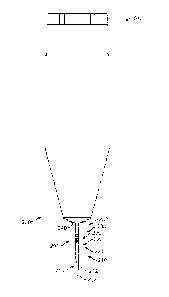
device implanted in the eye. The apparatus 200 comprise an elongate structure
201 comprising a distal portion 210, and intermediate portion 220 and a
proximal
portion 230. The elongate structure 201 extends along an axis 202 from a stop
240 to position the distal portion 210, the intermediate portion 220, and the
proximal portion 230 corresponding locations of the reservoir chamber. The
distal portion 210 comprises a distal tip 212 to penetrate tissue and the
penetrable barrier of the implantable device and an opening 214 to inject
therapeutic fluid into the implantable device. The intermediate portion 220
comprises a tapered section 224 to gradually increase a size of the channel
formed in the penetrable barrier when the needle is advanced through the
penetrable barrier, so as to maintain integrity of the penetrable barrier and
inhibit
CA 02848385 2014-03-10
WO 2013/040247
PCT/1JS2012/055216
damage to the penetrable barrier. In many embodiments, the tapered portion
224 may extend along axis 202 without holes so as to decrease pressure to the
penetrable barrier that may otherwise occur near the edge of a hole. The
proximal portion 230 may comprise a plurality of openings 236 to receive the
fluid
from the reservoir chamber of the implantable device. The proximal portion 230
may comprise an extension 238 extending from the stop 240. The extension 238
may extend from the stop 240 without holes to inhibit leakage when the fluid
is
exchanged and the stop 240 engages the conjunctiva.
[00130] Figure 5 shows the apparatus 200 coupled to an implantable device
100. The stop 240 is positioned to engage the conjunctiva 16, and the elongate
structure 201 extends through the conjunctiva 16 and penetrable barrier 184
into
the reservoir chamber 140 of the implantable device 100 when the apparatus 200
is coupled thereto. The elongate structure 201 can be sized so as to place
distal
tip 212 at a location within the reservoir chamber of the implantable device
when
the surface of the stop contacts the conjunctiva, for example. The distal tip
212
can be located on elongate structure 201 so as to place the distal tip 212 at
a
location from the penetrable barrier within implantable device 100 that is no
more
than a desired length, such as about % of the length 136 of the implantable
device, and in some embodiments no more than about half of the distance 136C
of the reservoir chamber. The plurality of openings 236 is located near the
penetrable barrier 184 so as to receive fluid contacting the reservoir
chamber.
The extension 238 extends substantially through the penetrable barrier 184,
for
example at least about half way through the penetrable barrier so as to
position
the plurality of openings away from an external surface of the penetrable
barrier
and to inhibit leakage.
[00131] Figure 6 shows an enlarged view of the elongate structure 201 of
the apparatus 200. The elongate structure 201 extends along axis 202 between
the distal tip 212 and stop 240. The distal portion 210 may comprise an
extension 211 having a substantially constant cross-sectional size extending
between the tip 212 to penetrate tissue and the intermediate portion 220. In
many embodiments, the extension 211 comprises a portion of a needle 270
26
CA 02848385 2014-03-10
WO 2013/040247
PCMJS2012/055216
extending between the stop 240 and the tip 212 to penetrate tissue, which tip
may comprise the tip of the needle to penetrate conjunctival tissue.
[00132] The tip to penetrate tissue 212 and the opening 214 can be located
a distance 204 from the stop and the plurality of opens to provide efficient
exchange of the fluid within the reservoir chamber of the implanted device. In
many embodiments, the opening 214 is placed within the reservoir chamber at a
distance from the stop 240 greater than the plurality of openings 236 to
inhibit
mixing of the injected therapeutic fluid with the fluid within the reservoir
chamber
of the implanted device. The opening 214 can be separated from the plurality
of
openings with a distance 208, such that the opening 214 can be located below
the plurality of openings when the therapeutic fluid is injected.
[00133] The therapeutic fluid may comprise a density greater than the fluid
of the implanted device and opening 214 can be placed below the plurality of
openings 236 when the therapeutic fluid is injected to inhibit mixing. The
axis
100A (see Figure 3A) of the implantable device and the corresponding axis of
the
reservoir chamber can be oriented away from horizontal, such that porous
structure 150 may be located below the penetrable barrier 184 when the
therapeutic fluid is injected. The axis 202 can oriented away from horizontal
such that opening 214 can be placed below the plurality of openings 236. The
therapeutic fluid comprising the greater density can flow toward the distal
end of
the therapeutic device and the displaced fluid of the implantable device
having
the lesser density can be received by the plurality of openings 236 located
above
the opening 214.
[00134] Examples of therapeutic agents and corresponding formulations
and fluids that may have a density greater than the density of the fluid
within the
chamber of the implanted device are listed in Table 1A. For example, one or
more of the therapeutic agent or a stabilizer can increase the density of the
therapeutic fluid. In many embodiments the therapeutic fluid having the
greater
density comprises a stabilizer, such as trehalose, and the therapeutic agent
such
as a protein comprising an antibody fragment. Alternatively or in combination,
the therapeutic formulation may comprise an amount of therapeutic agent
27
CA 02848385 2014-03-10
WO 2013/040247
PCMJS2012/055216
sufficient to provide a density greater than the fluid of the implanted
device. The
difference in density can be within a range from about 1% to about 10% and can
depend on the density of the fluid within the reservoir chamber of the
therapeutic
device and density of the therapeutic fluid placed in the reservoir chamber
with
the exchange apparatus. The density of the therapeutic fluid may correspond to
a density of the therapeutic agent and a density of the stabilizer (when
present).
In many embodiments, the density of the fluid of the reservoir chamber may
correspond to a density of phosphate buffered saline, or plasma, or an amount
of
therapeutic fluid remaining in the reservoir from a prior exchange, or
combinations thereof, for example.
[00135] When injected into a device implanted within the patient, the
distance 204 may correspond to no more than approximately the distance of the
reservoir chamber of device 140. The distance 204 may correspond
substantially to the length of the reservoir chamber so as to place the distal
tip
near the porous structure, and the elongate structure of the exchange
apparatus
can be aligned with an elongate axis of the implantable device. In many
embodiments, the distance 204 may correspond to no more than about half the
distance of the reservoir chamber, such that the elongate structure 201 can be
readily aligned with the implantable device. Work in relation to embodiments
suggests than a distance providing a tolerance for angular alignment error of
the
axis 100A with the axis 202 can facilitate exchange and improve efficiency of
the
exchange. The distance 204 from stop 240 to tip 212 comprising no more than
about half of the axial distance of the implantable device can facilitate
alignment
during injection.
[00136] The intermediate portion 220 may comprise an extension 222
extending between tapered portion 224 and the distal portion 210. The
extension
222 may comprise a cross-sectional size that is smaller than the tapered
portion
224. The extension 222 may comprise a smooth outer surface to penetrate
tissue. The tapered portion 224 may comprise a smother outer surface to
penetrate tissue and the penetrable barrier. The outer surface of the tapered
portion can extend at an angle of inclination relative to the axis, and the
tapered
28
CA 02848385 2014-03-10
WO 2013/040247
PCT/1JS2012/055216
portion 224 may comprise a conic section having an angle with the axis such
that
the outer surface extends at the angle of inclination relative the axis. The
angle
of inclination of the tapered portion 224 can be no more than about 25
degrees,
for example. The angle of inclination can be about 1 degree, about 2 degrees,
about 5 degrees, about 10 degrees, about 15 degrees, about 20 degrees, or
about 25 degrees, for example. The extension portion 216 may comprise a first
cross-sectional dimension, and the portion having the plurality of openings
may
comprise a second cross sectional dimension greater than the first dimension,
such that tapered portion having the angle of inclination extends there
between
to connect the extension portion 216 with the portion having the plurality of
openings 236.
[00137] The proximal portion 230 may comprise the plurality of openings
236 spaced apart along the axis 202 and distributed circumferentially around
the
proximal portion to receive fluid from a plurality of circumferential and
axial
locations when the stop 240 engages the conjunctiva to place the plurality of
openings within the reservoir chamber. At least one 237 of the plurality of
openings can be separated from the stop 240 with a distance 206 corresponding
substantially to the thickness of the penetrable barrier 184, such that the at
least
one 237 of the plurality of openings 236 can be placed near the inner surface
of
the penetrable barrier to receive fluid contacting the inner surface of the
penetrable barrier. In many embodiments, the thickness of the penetrable
barrier
is within a range from about 0.25 to about 2 mm, for example within a range
from
about 0.5 to about 1.5 mm, such that the thickness of the penetrable barrier
is
substantially greater than a thickness of the conjunctiva which can be
approximately 100 M. The distance 206 corresponding substantially to the
thickness of the penetrable barrier may correspond substantially to the
thickness
of the penetrable barrier and the epithelium of the patient.
[00138] A sheath 280 can be configured to extend over at least a portion of
needle 270. The sheath 280 may extend along the intermediate portion 220 and
the proximal portion 230, and the needle 270 can extend through the sheath.
The sheath 280 may comprise the plurality of openings 236 and provide one or
29
CA 02848385 2014-03-10
WO 2013/040247
PCT/1JS2012/055216
more channels extending along needle 270 to pass the fluid of the implantable
device through the septum.
[00139] The sheath 280 may comprise portions corresponding to the
intermediate and proximal portions of the elongate structure 201. The
extension
222 may comprise a distal portion sheath 280 having an inner surface sized to
engage an outer surface of the needle, and the diameter of the portion to
engage
the needle may comprise an inner cross sectional diameter less than the needle
to engage the needle with at least one or of pressure or friction. The tapered
portion 224 may comprise an intermediate portion of sheath 280, in which the
sheath 280 comprises tapered surface to penetrate the tissue and penetrable
barrier 184. The proximal portion 230 may comprise a proximal portion of the
sheath 280 comprising the plurality of openings 236 and the extension 238. A
channel 239 can extend along an outer surface of the needle to the plurality
of
openings 236. The channel 239 can extend proximally along extension portion
238 toward a container 250 (see Figure 8A) to receive the fluid of the
implantable
device. The channel 239 may couple the plurality of openings to the container
to
receive the fluid of the implantable device.
[00140] Figure 7 shows a cross-sectional view of an elongate structure of
the apparatus exchange fluid comprising the sheath 280 over the needle 270.
The needle may comprise channel 219, for example a lumen, extending distally
to the opening 214 (see Figure 6) and proximally to a connector to couple the
channel 219 to a syringe, for example. A wall 252 of container 250 comprises
sufficient strength to resist deformation when the stop 240 engages the
tissue,
and the stop 240 may comprise a deformable stop to couple to the tissue (see
Figure 8A). An outlet channel 254 extends from container 250 to at least one
vent opening 258 to atmospheric pressure (see Figure 8A).
[00141] Figure 7A shows an exchange apparatus comprising a locking
connector to couple to a syringe. The connector 290 may comprise a locking
connector having an extension 292 sized to fit in a channel of connector 320
of
syringe 300, for example (see Figure 8B). The exchange apparatus 200 may
comprise components of a standard locking needle assembly, for example a
CA 02848385 2014-03-10
WO 2013/040247
PCMJS2012/055216
standard locking needle such as a Luer-Lok TM fitting. The wall 252 that
defines
container 250 and sheath 280 can fit over the needle 270 which may comprise a
standard needle assembly. The wall 252 can extend a substantial distance from
stop 240 to opening 258, for example, so as to define container 250 and
channel
254 extending between the locking needle assembly and the wall.
[00142] Figure 7B shows the elongate structure 201 and receiver container
250 of the exchange apparatus 200 of Figure 7A. The wall 252 can extend
around a distal portion of receiver container 250. The needle 270 and sheath
280 may extend through the wall 250. The stop 240 can be located on a distal
portion of wall 252 and may comprise a soft material, for example a soft
elastomeric material such as silicone elastomer. The stop 240 may fit within a
recess formed on the surface of wall 252, and the needle 270 and the sheath
280
may extend through the soft elastomer stop 240, for example. The sheath 280
may comprise the tapered portion 224 proximal to the plurality of openings
236.
The needle 270 can extend from tip 212 through chamber 250 to the connector
290 (see figure 7A), for example. The sheath 280 can extend from a first end
281 distal of the tapered portion 224 to a second end 283. The second end 283
may comprise an opening 285 into chamber 250. The outflow path of the
displaced fluid from the implantable device may extend through the plurality
of
openings 236 to channel 239, along channel 239 to opening 285, and through
opening 285 and into receiver container 250.
[00143] Figure 7C shows sheaths suitable for combination with the
exchange apparatus of Figures 7A and 7B. The sheath 280 can be configured in
many ways (see 280A through 280K), and may comprise a wall thickness from
about 0.0001 inches to about 0.01 inches, for example about 0.001 inches
(1/1000 inch, 25 pm). The sheath 280 may comprise an inside diameter sized
larger than the outside diameter of needle 270 so as to provide an annular
channel extending axially between the needle and the sheath from the plurality
of
openings 236 to the opening 285. The diameter of each of the holes can be
within a range from about 0.0001 inches to about 0.1 inches, for example
within a
range from about 0.001 inches to about 0.01 inches.
31
CA 02848385 2014-03-10
WO 2013/040247
PCT/1JS2012/055216
[00144] The plurality of openings 236 may comprise one or more of many
shapes and can be arranged in many ways. Each row may comprise from about
2 to about 20 holes, for example, and may comprise circular, oval, elliptical
or
other shapes, for example. The sheath 280 may comprise a sheath 280A
having four rows of circular holes. Each of the holes may have a diameter of
no
more than about one half of the thickness of the outside diameter of the
sheath
280, for example, and may be located circumferentially at 90 degrees to each
other, for example. Each of the four rows may extend axially along the sheath
280. The rows can be spaced angularly at 90 degrees to each other, for
example.
[00145] The sheath 280 may comprise sheath 280B having about two rows,
each row comprising about four holes, each hole having a diameter of no more
than about one eighth of the diameter of the outside diameter of the sheath
280.
The two rows may be spaced apart circumferentially at 180 degrees, and the
holes may comprise holes cross-cdrilled through both sides of the sheath, such
that each hole has a corresponding hole on the other row on an opposite side
of
the sheath.
[00146] The sheath 280 may comprise sheath 280C comprising about four
cross drilled holes, each hole having a diameter of no more than about three
quarters of the diameter of the outside diameter of the sheath 280, for
example.
The holes may comprise pairs of holes, in which the holes of each pair have
corresponding axial locations. The holes can be arranged in two rows spaced
circumferentially at 180 degrees.
[00147] The sheath 280 may comprise sheath 280D comprising at least
about three rows of at least about 3 holes, each hole having a diameter of no
more than about one quarter of the diameter of the outside diameter of the
sheath 280. The rows can be spaced apart circumferentially at about 120
degrees, for example.
[00148] The sheath 280 may comprise sheath 280E comprising at least
about 40 holes, each hole having a diameter of no more than about one tenth of
the diameter of the outside diameter of the sheath 280.
32
CA 02848385 2014-03-10
WO 2013/040247
PCMJS2012/055216
[00149] The sheath 280 may comprise sheath 280F comprising slots. Each
of the slots may comprise a narrow dimension across and a long dimension
across. The long dimension can extend axially along the sheath 280 and may
extend a distance greater than the narrow dimension across. The long
dimension can extend a distance greater than the outside diameter of the
sheath
280 where the slots are located, for example. The narrow dimension across
each slot may comprise no more than about half of the outside diameter of the
sheath, for example.
[00150] The sheath 280 may comprise sheath 280G comprising staggered
rows of holes. The plurality of openings 236 may comprise a first row and a
second row of cross drilled holes 236A, in which the holes of the first row
are
paired with the holes of the second row at a common axial location for each
pair.
A third row of holes and a fourth row of holes may comprise cross drilled
holes
236B located at 180 degrees to each other and 90 degrees to the first row and
the second row. The axial locations of the third and fourth rows of holes can
be
staggered from the first and second rows of holes, such that the axial
locations of
the holes 236A of the first row and second row correspond to axial locations
away from the holes 236B of the first row and the second row, for example.
[00151] The sheath 280 may comprise sheath 280H comprising oval holes
having a long dimension and a short dimension, with the long dimension
extending transverse to the axis of the sheath 280 and the short dimension
extending along the axis of the sheath 280. The oval holes can be spaced apart
and located in rows extending along the axis of the sheath as described
herein,
for example.
[00152] The sheath 280 may comprise sheath 2801 comprising elongate
oval holes having the long axis of the oval extending along the axis of the
sheath
and the narrow dimension of the oval extending transverse to the long axis of
the
sheath, for example.
[00153] The sheath 280 may comprise sheath 280J comprising at least
about three rows of at least about 3 oval holes, each oval hole having a
maximum dimension across of no more than about one quarter of the diameter of
33
CA 02848385 2014-03-10
WO 2013/040247
PCT/1JS2012/055216
the outside diameter of the sheath 280. The rows can be spaced apart
circumferentially at about 120 degrees as described herein, for example.
[00154] The sheath 280 may comprise sheath 280K comprising at least
about 40 holes, each hole having a diameter of no more than about one tenth of
the diameter of the outside diameter of the sheath 280. The holes can be
located on opposite sides of the sheath 280, and may comprise cross drilled
holes, for example.
[00155] Figure 7D shows one of the sheath openings 236 having a beveled
channel surface 284 to inhibit degradation of the penetrable barrier. The
thickness 286 of the sheath wall may be within a range from about 0.0001 to
about 0.01 inches, for example. The corner of 282 of the beveled channel
surface of the opening may comprise an angle to inhibit degradation of the
penetrable barrier, such as tearing with repeated injections.
[00156] Figure 7E shows one of the sheath openings 236 having a rounded
channel surface of the opening and edge to inhibit degradation such as tearing
of
the penetrable barrier with repeated injections, in accordance with
embodiments
of the present disclosure;
[00157] Figure 7F shows a schematic illustration of the parallel outflow
paths from the reservoir chamber 140. The first outflow path 140P1 extends
from the reservoir chamber 140 to the receiver container 250, and the second
outflow path 140P2 extends from the reservoir chamber 140 across the porous
structure 150 to the vitreous humor 30 of the eye. As the intraocular pressure
of
the eye may be substantially less than the pressure of the implantable device
during exchange, the intraocular pressure of the eye approximates atmospheric
pressure. The second outflow path 140P2 extends comprises a pressure drop
DP across the porous structure 150. The first outflow path 140P1 comprises the
pressure drop DP across the plurality of openings 236, along the one or more
channels 239 extending from the plurality of openings to the opening 285, and
through the one or more openings 285 into the receiver container 250. In many
embodiments, the channel 254 and the opening 258 each comprise air, such that
the resistance to flow 254R of the channel 254 and the resistance to flow 258R
of
34
81778198
the opening such that the pressure drop across channel 254 and the opening
258 can be substantially less than the pressure drop DP, for example
negligible.
[00158] In many embodiments, a valve 256V can be provided, so as to
vary
the resistance to flow of the outflow path to provide a bolus. The valve 256V
may
comprise a porous structure 256, for example, or a stop, plunger or other
mechanism so as to increase pressure and provide the bolus when the exchange
apparatus 200 has received a predetermined amount of displaced liquid from the
reservoir container 140. The porous structure 256 may comprise a gas such as
air initially, and be configured to contact the liquid from the reservoir
chamber
when the predetermined amount of fluid has been received and provide a
substantial increase in the resistance to flow 156R, such that the bolus is
passed
through porous structure 150. Examples of valves and mechanisms to provide
the bolus injection are described in U.S. PCT Pat App. No.
PCT/US2011/046812, filed August 5, 2011, entitled "Injector Apparatus and
Method for Drug Delivery", PCT Publication NO. WO/2012/019136.
[00159] The pressure drops can be configured in many ways so as to
inhibit
a bolus release into the eye when the therapeutic fluid is exchanged with the
implantable device fluid, or so as to release a bolus of therapeutic fluid
through
the porous structure of the implantable device, for example. The therapeutic
fluid
260 comprising therapeutic agent 110 is injected through needle 270 into the
reservoir chamber 140 of the implantable device, so as to pressurize the
implantable device chamber with a force sufficient to pass a substantial
portion of
the implantable device fluid 262 into the receiver container 250. A pressure
drop
DP extends from the reservoir chamber of the implantable device through the
plurality of openings 236, along channel 239 extending to opening 285, and
through opening 285, such that the implantable device fluid 262 is received in
receiver container 250. The outflow path from the reservoir chamber of the
implantable device to the receiver container 250 comprises a resistance to
flow
corresponding to a resistance to flow 236R of the plurality of openings 236,
the
resistance to flow 239R of the channel 239, and the resistance to flow 285R of
CA 2848385 2018-12-06
CA 02848385 2014-03-10
WO 2013/040247
PCMJS2012/055216
opening 285, for example. The resistance 150R to flow of the porous structure
corresponds to an amount of therapeutic fluid 260 passed from the reservoir
chamber of the implantable device to the chamber of the eye containing
vitreous
humor, for example. The amount of fluid into the receiver container such as
the
chamber 250 relative to the amount of fluid through the porous structure is
related to the resistances based on parallel flow. The amounts of flow to the
receiver container 250 and through the porous structure 150 correspond
substantially to the following equations:
(Amount through porous structure)/(Amount through receiver) = (Resistance
236R + Resistance 239R)/(Resistance 150R)
(Amount through porous structure) = (Amount through receiver) *(Resistance
236R + Resistance 239R)/(Resistance 150R)
(Amount to receiver container) = (Amount through porous structure)
*(Resistance 150R)/ (Resistance 236R + Resistance 239R)
[00160] The resistance 150R corresponding to extended release of the
therapeutic agent can be substantially greater than the resistance of the
outflow
path to the receiver container 250 comprising resistance 236R and resistance
239R, such that the amount of bolus of therapeutic fluid 260 and implantable
device fluid 262 through the porous structure 150 can be less than about 1 pL
combined, for example. Alternatively, the resistance to flow of the outflow
path
can be sufficient such that a substantial amount of therapeutic agent 110 is
released through porous structure 150 with a bolus during exchange. The
resistance to flow along the outflow path may comprise one or more of the
resistance to flow 236R of the plurality of openings 236, the resistance to
flow
239R of the channel 239 extending from the plurality of openings to the
opening
285, or the resistance to flow 285R of the opening 285, for example, or
combinations thereof. The size and number of the plurality of openings 236 and
the thickness 286 of the sheath can determine substantially the resistance
236R
of the plurality of openings. The length of the channel 239 extending from the
36
CA 02848385 2014-03-10
WO 2013/040247
PCMJS2012/055216
plurality of openings 236 to the opening 285, and the transverse dimensions of
the channel can determine substantially the resistance to flow 239R. For
example the channel 239 may comprise a plurality of channels extending from
the plurality of openings opening 236 to the reservoir container 250.
[00161] The resistance to flow 150R can vary with the RRI of the porous
structure 150. In many embodiments, the resistance to flow 150R of porous
structure 150 is inversely related to the RRI of the porous structure. For
example, experimental testing with syringes and test therapeutic devices has
shown that a bolus can be achieved through a porous structure 150 having an
RRI of about 0.06 when the resistance to flow of outflow path is sufficiently
large
and device 100 is constructed such that chamber 140 can be pressurized to at
least about one atmosphere, for example. However, porous structures having
lower RR's can provide a substantial resistance to flow so as to inhibit
release of
a substantial bolus. For example a porous structure 150 having an RRI of about
0.02 has a resistance to flow 150R such that an attempt to pass a substantial
bolus amount through the porous structure 150 with a clinically acceptable
injection time of 30 seconds or less may result in substantial pressure, for
example greater than about four atmospheres.
[00162] The resistance to flow 150R of the porous structure 150 comprising
the plurality of straight channels 150SC varies with one or more of the
combined
cross-sectional surface area of the channels 150SC, the number of openings,
the
size of each of the openings, or the thickness 150T, and combinations thereof.
The combined cross-sectional surface area of the channels 150SC may be no
more than about 100,000 pM2, so as to provide a resistance to flow 150R of the
porous structure 150 sufficient decrease flow through the porous structure and
provide exchange as described herein. The combined cross-sectional surface
area can be within a range from about 1000 pM2 to about 100,000 i.tm2, for
example, so as to provide a resistance to flow 150R greater than the
resistance
to flow of the outflow path 140P1. For example, the combined cross-sectional
area within a range from about 1,000 pM2 to about 30,000 p,M2 may provide a
substantial resistance to flow 150R, which may be substantially greater than
the
37
CA 02848385 2014-03-10
WO 2013/040247
PCMJS2012/055216
resistance to flow of the outflow path. In many embodiments, the combined
surface area is within a range from about 1,000 iffr12 to about 10,000 um2,
and
the resistance to flow 150R is substantially greater than the resistance to
flow of
the outflow path so as to inhibit bolus release through the porous structure
(see
also figures 3A and 3B).
[00163] The resistance to flow of the outflow path comprising resistance
236R and 239R may comprise about 5 per cent of the resistance 150R to flow of
the porous structure 150, such that about 5 1_ of fluid flows through the
porous
structure and about 954 flows through the plurality of openings 236 and
channel 239. The size and number of the plurality of openings and dimensions
of channel 239 can be determined by a person of ordinary skill in the art
based
on the teachings described herein so as to provide a target amount of bolus
for a
target amount of injected therapeutic fluid.
[00164] As the therapeutic fluid 260 can be denser than the implantable
device fluid 262, a substantial portion of the fluid through the porous
structure
150 may comprise the therapeutic fluid 260, for example.
[00165] Figure 8A shows a cross-sectional view of the apparatus to
exchange fluid as in Figures 5 and 6 coupled to a syringe. The channel 239
extends from the plurality of openings 236 to a container 250 to receive the
fluid
of the implantable device. The distal portion 210 comprising tip 212 and
opening
214 comprise a distal portion of needle 270. The channel 219 extends along an
axis 202 from the opening 214 to a connector 290. The connector 290 is
configured to couple to a connector 320 of an injector. The injector may
comprise a syringe 300 (not to scale). The injector may comprise a container
310 comprising a therapeutic fluid for injection, and the container 310 can be
fluidically coupled to the opening 214 on distal tip 212 when the connector
320
engages the connector 290.
[00166] The sheath may comprise an annular configuration shaped for
placement over the substantially annular needle, such that the sheath and
needle
comprise a substantially concentric configuration extending along axis 202.
38
CA 02848385 2014-03-10
WO 2013/040247
PCMJS2012/055216
[00167] The connector 290 of the exchange apparatus and the connector
320 of the injector can be configured in many ways. For example, the connector
290 and the connector 320 may comprise a standard connector such as a Luer
connector or a pressure fit connector. Alternatively, the connector 290 may
comprise a non-standard connector to limit access to the exchange apparatus
200. For example the connector 290 may comprise a star connector or other
connector, and connector 290 may comprise a lock and key mechanism. The
lock and key mechanism may comprise a lock on the exchange apparatus
configured to receive a key of the injector, such that the lock of connector
290
can receive the key of connector 320 to couple the injector to the exchange
apparatus and permit injection from chamber 310 through opening 214.
Alternatively, the syringe 300 may be affixed to exchange apparatus 200, and
syringe 300 provided with a single dose of therapeutic agent.
[00168] The container 250 of the exchange apparatus may have a volume
to limit and amount of fluid received from the implantable device and to limit
use
of the apparatus to a single use. For example, the volume of the container may
comprise no more than about 100 uL, for example no more than about 50 uL, so
as to limit and amount of fluid exchanged with the implantable device and
inhibit
reuse of the exchange apparatus from patient to patient. The implantable
device
can be provided to a health care provider with an amount of gas, such as air
within the receiver container 250, and the receiver container may comprise a
structure along a vent path to limit the amount of fluid that can be received
by the
container 250.
[00169] The exchange apparatus 200 may comprise a porous structure 256
to inhibit passage of the fluid of the implantable device and limit the amount
of
fluid exchanged. The porous structure 256 may comprise a material to pass a
gas, such as air and inhibit flow of a liquid, such as the fluid of the
implantable
device. The material may comprise one or more of a fabric, a porous fabric, a
semipermeable membrane, an air permeable material, a moisture vapor transfer
waterproof fabric, a hydrophilic porous material, or a porous sintered
material, for
example. The channels extending through the porous structure 256 may
39
CA 02848385 2014-03-10
WO 2013/040247
PCT/1JS2012/055216
comprise a gas, such as air and a lower resistance to flow of the gas and a
substantially greater resistance to flow of a liquid, such as the therapeutic
fluid,
such that the exchange is substantially inhibited when receiver container 250
is
substantially filled with fluid of implanted device and the fluid exchanged
with the
implanted device contacts the porous structure 256. The porous structure 256
may comprise one or more of a fabric, a porous fabric, a semipermeable
membrane, an air permeable material, a moisture vapor transfer waterproof
fabric, a hydrophilic porous material, or a porous material or a porous
sintered
material, for example.
[00170] The exchange apparatus may comprise a structure 259 composed
of a material penetrable with a needle to draw a sample from the receiver
container. The structure 259 may comprise one or more materials suitable for
penetration with a needle such as one or more of rubber or silicone elastomer,
for example. The structure 259 may comprise the porous structure 256, for
example, and the material penetrable with the needle may comprise one or more
of a fabric, a porous fabric, a semipermeable membrane, an air permeable
material, a moisture vapor transfer waterproof fabric, a hydrophilic porous
material, or a porous material or a porous sintered material, for example.
[00171] Figure 8B shows an embodiment of an implantable therapeutic
device 100 comprising a lock and key mechanism 850 to place a therapeutic
agent in the implantable device. The lock and key mechanism 350 comprises a
lock 360 and a key 370. The lock 360 can be located on the implantable device
to inhibit access to the reservoir chamber of the implantable device. The
exchange apparatus 200 comprises the key 370 to access the reservoir chamber
to place the therapeutic agent 110 as described herein. The lock can be
configured in many ways and may comprise one or more of a deflected channel,
a curved channel, a helical channel, a serpentine channel, engagement
structures, a magnet, a door, a movable door, a tumbler, a cylinder, pins or a
shear line, for example. The key can be configured in many ways so as to
correspond to the lock and may comprise one or more of a deflectable elongate
structure, a curved elongate structure, a helical elongate structure, a
serpentine
CA 02848385 2014-03-10
WO 2013/040247
PCMJS2012/055216
elongate structure, engagement structures sized to engage engagement
structures of the lock, for example.
[00172] In many embodiments, the lock 360 inhibits access with a straight
rigid needle, so as to inhibit placement of the therapeutic agent which may be
ineffective or inappropriate when placed in the therapeutic device. For
example,
the exchange apparatus 200 can be delivered to the physician with a
predetermined therapeutic agent formulation and key, and the implantable
device
has the lock configured to receive the key to place the therapeutic agent,
such
that access to the implantable device can be limited substantially.
[00173] In many embodiments, the lock 360 comprises the deflected
channel 364, which may comprise one or more of a bent channel, a curved
channel, a helical channel, or a serpentine channel, for example. The lock 360
may comprise a stiff substantially non-penetrable biocompatible material, for
example one or more of rigid plastic, polymethylmethacrylate (hereinafter
"PM MA"), polycarbonate, metal, or titanium, for example. The key 370 may
comprise one or more of many components and structures of elongate structure
201 as described herein. The key 370 may comprise one or more of a
deflectable key or a deflected key configured to extend along the deflected
channel 364 to deliver the therapeutic fluid 260 and receive the implantable
device fluid 262. The lock comprises an engagement structure 362 to engage an
engagement structure 372 of the key. The engagement structure 362 may
comprise an inner surface of the channel 364, and the outer surface of the
deflectable key engages the inner surface of the channel so as to deflect the
elongate structure 201 to advance along channel 364.
[00174] Figure 8B1 shows an embodiment of a deflectable elongate
structure 201 in an unloaded configuration prior to insertion in the lock 360
of
Figure 8B. The elongate structure comprises an axis 202, and the elongate
structure may extend substantially along the axis 202 so as to provide column
strength to the elongate structure 201 to penetrate the penetrable barrier 184
of
access port 180. The elongate structure 201 may comprise a resistance to
deflection sufficiently low so as to advance along channel 364 and a column
41
CA 02848385 2014-03-10
WO 2013/040247
PCT/1JS2012/055216
strength sufficient to penetrate tissue and the penetrable barrier. The
deflectable
elongate structure 201 can be deflected substantially away from axis 202 when
advanced into the lock 360.
[00175] The lock 360 may comprise a rigidity sufficient to inhibit
penetration
with a straight needle, and the channel 364 can be extend internally with lock
360.
[00176] The key 370 comprising the elongate structure 201 can extend
through tissue such as the conjunctiva and epithelium to reach the lock 360,
and
the key can be configured to penetrate the tissue. The penetration of the
tissue
and penetrable barrier 184 inhibits contamination of the reservoir chamber as
the
barrier function of the conjunctiva 16 and Tenon's capsule 17 can be
substantially maintained. The deflectable elongate structure 201 can be made
of
one or more of many components and may comprise sheath 280 and needle
270. The needle and sheath can be configured to deflect together when
advanced along channel 364. The deflectable needle may comprise a metal, for
example Nitinol, and the sheath may comprise a polymer such as polyimide, for
example.
[00177] Figure 8B2 shows an embodiment of a deflected elongate structure
201 in an unloaded configuration prior to insertion in the lock of Figure 8B.
The
key 370 comprising deflected elongate structure may comprise one or more of
many materials providing a stiffness sufficient to retain the deflected shape
in the
unloaded configuration. In the unloaded configuration, the deflected elongate
structure 201 of key 370 extends away from axis 202. The deflected elongate
structure 201 may comprise a preformed deflection profile corresponding to the
path of channel 364 extending through the lock 360 from a first side of the
lock
toward the conjunctiva to a second side of the lock toward the reservoir
chamber
140.
[00178] Figure 8C1 shows an embodiment of an implantable therapeutic
device 100 comprising a lock 360 and an exchange apparatus 200 comprising a
rotatable key 370 to the lock 360. The exchange apparatus 200 can be
advanced toward the implantable device 100 and rotated as shown with arrows
42
CA 02848385 2014-03-10
WO 2013/040247
PCT/1JS2012/055216
374. The engagement structures 372 of the key couple to the engagement
structures 362 of the lock, such that the lock 360 opens to allow access of
the
elongate structure 201. The engagement structures may comprise one or more
of many structures, for example magnets, teeth, or notches, and the engagement
structures can be spaced apart at appropriate distances such that the
engagement structures of the lock are keyed to the engagement structures of
the
key to allow access. For example the engagement structures 372 of the key may
comprise magnets, and the engagement structure of the lock may comprise a
magnetic material such that the key can be opened with the lock and the
magnetic field extending through the conjunctiva 16 and the Tenon's capsule
17,
for example. Alternatively, the conjunctiva and/or Tenon's capsule can be
displaced and the engagement structures 372 of the key can contact the
engagement structures 362 of the lock to allow access to the reservoir
chamber.
[00179] Figure 8C2 shows an embodiment of the implantable therapeutic
device 100 of Figure 801 in a unlocked configuration in which the elongate
structure 201 extends through the open lock and penetrable barrier 184 to
access the reservoir chamber 140 of the implantable device 100. The exchange
apparatus can place the therapeutic fluid 260 in the implantable device 100
and
receive the implantable device fluid 262 in the receiver container 250 as
described herein.
[00180] Figure 8D1 shows an embodiment of an implantable therapeutic
device comprising 100 a slide lock 360 and exchange apparatus 200 comprising
a slidable key to engage the slide lock. The exchange apparatus 200 can be
advanced toward the implantable device 100 and slid as shown with arrows 374.
The engagement structures 372 of the key couple to the engagement structures
362 of the lock, such that the lock 360 opens to allow access of the elongate
structure 201. The engagement structures of the slide lock 360 and slide key
370 may comprise structures similar to the rotatable key and lock described
with
reference to Fig. 801.
[00181] Figure 8D2 shows an embodiment of an implantable therapeutic
device 100 in an unlocked configuration in which the elongate structure 201
43
CA 02848385 2014-03-10
WO 2013/040247
PCT/1JS2012/055216
extends through the open lock 360 and penetrable barrier 184 to access the
reservoir chamber 140 of the implantable device. The exchange apparatus can
place the therapeutic fluid 260 in the implantable device 100 and receive the
implantable device fluid 262 in the receiver container 250 as described
herein.
[00182] Figure 8E shows an embodiment of an implantable therapeutic
device 100 comprising a lock 360 and the elongate structure 201 of the
exchange apparatus 200 comprising the key 370. The elongate structure 201
can be configured in many ways so as to comprise the key 370. The
engagement structures 372 of the key 370 can be located near a distal end 212
of the elongate structure 201, for example. The engagement structures 272 can
be affixed to the needle 270 and may comprise annular structures extending
around the needle. Alternatively or in combination, the sheath 280 of the
elongate structure may comprise the engagement structures. For example, the
one or more openings 289 of the sheath 280 can be sized and located so as to
comprise the engagement structures 372 of the key 370.
[00183] The lock can be configured in many ways to receive the key, and
the engagement structures 362 of the lock may comprise pins aligned to a shear
plane 368 when the key is inserted, for example.
[00184] Figure 9 shows a container 400 to receive and store the exchange
apparatus 200. The container 400 may comprise a barrier material 410 to
inhibit
evaporation from within the container to the outside environment, a cap 430
and
a base supporting a soft penetrable material 420. The cap 430 may comprise a
protrusion such as an annular protrusion 432 to seal around an outer portion
of
the wall of the container. The cap 430 may comprise a retention structure to
hold
the injector apparatus, for example a second protrusion, such as an annular
protrusion 434 to receive and hold the exchange apparatus 200. The cap 430
may comprise a soft barrier material, such as an elastomer, for example.
[00185] Figure 10 shows an exchange apparatus 200 having the
implantable device fluid 262 comprising a fluid sample 264 within the receiver
container 250. The receiver container 250 can be coupled to the elongate
structure 201. The channel 254 can extend from the container to 250 to opening
44
CA 02848385 2014-03-10
WO 2013/040247
PCT/1JS2012/055216
258. The receiver container 250 may comprise a combination of one or more of
the therapeutic fluid 260, the implantable device fluid 262 comprising sample
fluid
264. Depending on the exchange apparatus and orientation, the implantable
device fluid 262 comprising sample fluid 264 may comprise a substantial
majority
of the fluid of the receiver container 250.
[00186] Figure 11 shows the exchange apparatus 200 having the fluid
sample 264 placed partially within the storage container 400. The cap 430 is
shown over but not yet covering the vent channel 254 extending from the
receiver container 250 to the opening 258.
[00187] Figure 12 shows a cap 430 of the storage container placed over the
outlet channel opening 258 of channel 254 coupled to the receiver container
250
of the exchange apparatus, so as to inhibit one or more of leakage or
evaporation from container 250.
[00188] Figure 13 shows an elongate structure 201 of the exchange
apparatus placed within a soft penetrable material 420 near the bottom of the
storage container and the cap placed over the container so as to seal the
exchange apparatus container. The soft penetrable material 420 may comprise
a soft material capable of sealing, for example a soft elastomeric material
such
as silicone elastomer.
[00189] Figure 14 shows an apparatus 500 to remove the sample fluid from
the receiver container 250 of the exchange apparatus 200. The apparatus 500
comprises a sample container 400, a plug 520, a syringe 540 to pressurize the
receiver container 250, and a coupling 530 to couple the syringe to the
receiver
container of the exchange apparatus 200. The coupling 530 may comprise a
receptacle 536 to receive the proximal end portion of the exchange apparatus
200. The receptacle 536 may comprise a structure 532 to couple the syringe to
the coupling, for example a Luer connector, a Luer-LokTM connector, or other
known connector, for example. The retention structure 532 to retain the
exchange apparatus 200 and a contact structure 534 to contact the outer wall
of
the exchange apparatus and fluidly couple the syringe to the opening 528 when
the exchange apparatus 200 is retained with the coupling 530. The contact
CA 02848385 2014-03-10
WO 2013/040247
PCT/1JS2012/055216
structure 534 may inhibit flow of injection fluid from syringe 540, such as
air,
between the retention structure 532 and wall 252 of the exchange apparatus,
for
example with a seal between the retention structure 532 and the wall 252 of
the
exchange apparatus 200.
[00190] Figure 15 shows a cap 520 placed on the connector 290 to couple
the syringe to the exchange apparatus, so as to inhibit fluidic flow from
syringe
540 through the needle of the elongate structure 201.
[00191] Figure 16 shows the exchange apparatus placed within receptacle
536 of the coupling 530 so as to couple the receiver container 250 with the
syringe 540. The syringe 540 can pressurize the channel 254 so as to displace
the implantable device fluid comprising the sample fluid 264 from the receiver
container 250 into a sample container 400 for analysis. The annular protrusion
534 can engage the outer wall 252 of the exchange apparatus 200 form a seal
and pressurize chamber 250 when the plunger of syringe 540 is depressed. The
pressurization of chamber 250 urges the implantable device fluid 262
[00192] Figure 17 shows an exchange apparatus 200 coupled to a
removable receiver container 250. The removable container 250 may comprise
a penetrable barrier, for example a septum. The exchange apparatus 200 can
be coupled to a syringe 300. The exchange apparatus can be coupled to a
device 100 implanted in an eye with the elongate structure 201 configured to
extend through the conjunctiva 16 and the penetrable barrier 184. The exchange
apparatus may comprise a first channel coupled to the plurality of openings to
receive the fluid from the implantable device, and a second channel coupled to
a
vent. The first channel 239 may extend to a first needle 710 to puncture
container 250 and the second channel may extend to a second needle 720 to
puncture the container 250. The first needle may have a first opening 712, and
the second needle may have a second opening 722. The first opening can be
located below the second opening, such that the second opening allows air to
pass when liquid passes through the first opening.
[00193] Figure 18 shows the exchange apparatus 200 coupled to the
implanted device 100 so as to exchange fluid and receive sample fluid 264 from
46
CA 02848385 2014-03-10
WO 2013/040247
PCMJS2012/055216
the implanted device. The container 250 can be coupled to the exchange
apparatus during exchange.
[00194] Figure 19 shows the exchange apparatus 200 removed from the
implanted device 100 and the receiver container 250 detached from the
exchange apparatus 200. The sample fluid 264 from the implantable device can
be contained within the container 250.
[00195] Figure 20A shows components of a container 400 to remove a
sample fluid 264 from exchange apparatus 200. The container 400 may
comprise a sealable container having a wall composed of a barrier material 410
to inhibit evaporation, a cap 430 and an annular protrusion 432. A support 450
can be placed within container to receive and hold the exchange apparatus 200
within the container. The support 450 may comprise a piece of soft elastomeric
tubing such as silicone tubing, for example.
[00196] Figure 20B shows an exchange apparatus 200 placed in the
container 400 having components as in figure 20A. The exchange apparatus is
placed such that the wall 252 of container 250 rests on the support 450. The
elongate structure 201 extends below the support 450. The container 400
comprises an axis 400A, which axis may be aligned with the axis of exchange
apparatus 200. The opening 258 coupled to container 250 with channel 254 is
exposed to air.
[00197] Figures 20C and 20D show removal of implantable device fluid 262
comprising sample fluid 264 from exchange apparatus. The sample fluid 264
may be drawn into the container 400 with aspiration. A syringe 300 can be
coupled to the exchange apparatus 200 with a connector 320 such as a locking
connector, for example. The syringe 300 may comprise a piston 302 connected
to a plunger 304 which allows the piston to be advanced and pulled back. The
syringe 300 comprises a chamber 310 having a volume defined with the location
of piston 302.
[00198] The piston of the syringe can be drawn outward to draw air from
chamber 440, which chamber draws sample fluid 264 into chamber 440.
47
CA 02848385 2014-03-10
WO 2013/040247
PCT/1JS2012/055216
[00199] Figure 21 shows a method 1800 of removal from an exchange
apparatus with a removal container as in Figures 20A to 20D. A step 1810
removes the exchange apparatus 200 from the syringe after injection of the
therapeutic fluid. The implantable device fluid comprising the sample fluid is
contained in the receiver container 250.
[00200] A step 1810 removes therapeutic fluid 260 from the needle of the
elongate structure 201 with injection of a gas comprising air from a syringe
300.
[00201] A step 1820 depresses the plunger towards the needle.
[00202] A step 1830 places the exchange apparatus 200 on the support
450 of container 400 with the exchange apparatus coupled to syringe 300. The
support 450 coupled to exchange apparatus 200 may define a chamber 440.
The support 450 can be shaped to inhibit air flow between and outer surface of
the exchange apparatus and an inner surface of the support 450, for example
with a seal formed between the outer surface of the exchange apparatus 200 and
the inner surface of the support 450. The support may comprise a soft
material,
such as a soft elastomeric material, for example.
[00203] A step 1840 draws air from chamber 440 with syringe 300 through
the injection needle of the elongate structure extending into chamber 440. The
implantable device fluid 262 comprising sample fluid 264 is displaced from the
receiver container with air drawn into the receiver container 250 through
opening
258 of channel 254. The implantable device fluid 262 comprising sample fluid
264 falls to the lower end of chamber 440 and is contained on an inner surface
of
container 400.
[00204] A step 1850 removes the exchange apparatus 200 and syringe 300
from the sample container 400. The cap 430 is placed on the container 400, so
as to inhibit evaporation of the implantable device fluid 260 comprising
sample
fluid 264.
[00205] Figure 22 shows an exchange apparatus 200 having a receiver
container 250 comprising a penetrable barrier structure 259 on a side port to
remove a sample from the receiver container with a needle and syringe. The
syringe can draw implantable device fluid 262 comprising sample fluid 264 from
48
CA 02848385 2014-03-10
WO 2013/040247
PCMJS2012/055216
the receiver container 250 through a needle 330 passing through the penetrable
barrier structure 259 on the side port.
[00206] Figure 23A shows an exchange apparatus 200 having a receiver
container 250 coupled to a sample container 400 and a syringe 300 to displace
fluid from the receiver container 250. The sample container 400 is placed over
the plurality of openings 236 and a needle 330 of a syringe 300 extends into a
chamber 440 the sample container. The syringe 300 can draw fluid from
chamber 440 so as to displace fluid from the receiver container 250. The
channel
254 extends from container 250 to opening 258. Fluid drawn through needle 330
into syringe 300 urges the implantable device fluid 262 comprising sample
fluid
264 through the one or more openings comprising the plurality of openings 236,
and air can move inward through opening 258 and along channel 254 to displace
the implantable device fluid 262 comprising sample fluid 264. The needle 270
extends through the sample container 400 such that the distal end of the
needle
extends beyond sample container 400. The plurality of openings 236 may
comprise a plurality of openings of sheath 280.
[00207] Figure 23B shows the sample container 400 of Figure 23A placed
over the plurality of openings 236 of the exchange apparatus. The sample
container 400 may comprise a first penetrable barrier comprising penetrable
barrier material 420 and a second penetrable barrier comprising penetrable
barrier material 420. A first septum 422 can be located opposite a second
septum 422, for example. The elongate structure 201 can extend through the
first penetrable barrier and the second penetrable barrier so as to position
the
one or more openings between the first penetrable barrier and the second
penetrable barrier. The sample container 400 may comprise a wall composed of
a barrier material 410, and the wall may comprise an amount of rigidity
sufficient
to resist deflection when the sample is drawing with needle 330. The wall may
comprise an annular shape, for example a tubular geometry. The needle 270
may extend through the second penetrable barrier so as to inhibit fluidic
coupling
of the syringe 300 and needle 330 with the opening on the distal end of needle
270. The sample container 400 can be shaped in many ways, for example with a
49
CA 02848385 2014-03-10
WO 2013/040247
PCMJS2012/055216
spherical ball or other shape having a walls composed of penetrable barrier
material 410 such that the needle tip can extend through both side of the
container 400.
[00208] Figures 24A and 24B show an exchange apparatus having a
receiver container 250 coupled to a syringe 300 with a sample container 400
placed over openings 236 of the exchange apparatus 200 so as to remove a
sample fluid 264 from the receiver container 250. The sample container 400
comprises a chamber 440 enclosed with a wall comprising a barrier material 410
and a penetrable barrier material 420, in which the penetrable barrier
material
may comprise a septum, for example. The wall of the container 400 may
comprise one or more of many shapes such as annular, spherical, cubic,
ellipsoidal or oval, for example. The elongate structure 201 comprising needle
270 and sheath 280 can be advanced into the container 400 so as to place at
least one opening of the plurality of openings 236 within the chamber 440 and
the distal needle tip comprising the opening to place therapeutic fluid within
the
chamber 440. The needle can be coupled to syringe 300, and fluid drawn from
chamber 440 with syringe 300 through an opening in the distal tip of needle
270.
The fluid drawn through the needle 270 is replaced with the fluid passed
through
the plurality of openings 236.
[00209] The receiver container 250 comprising the implantable device fluid
262 comprising sample fluid 264 is fluidically coupled to the plurality of
openings
as described herein such that the implantable device fluid 262 comprising the
therapeutic fluid 264 is passed through the plurality of openings. The channel
254 extends from the receiver container 250 to the opening 258 such that air
may be drawn into the receiver container 250 to replace the volume of the
displaced implantable device fluid 262 comprising sample fluid 264. In many
embodiments, the implantable device fluid 262 comprising the sample fluid 264
comprises a liquid comprising water as described herein.
[00210] Figure 25A shows an exchange apparatus 200 comprising a
removable receiver container 250 comprising a removable sheath 280 placed
over a needle 270. The receiver container 250 may comprise the sample
CA 02848385 2014-03-10
WO 2013/040247
PCMJS2012/055216
container 400. The wall 252 of container 250 and needle 270 can be configured
for removal and separation from the needle 270 so as to provide the sample
container 400. The sheath 280 may be supported on a distal end of the wall 252
of container 250, such that the sheath 280 can be supported with the wall 252
of
container 400 when removed. A plug 960 comprising penetrable barrier material
420 can be placed over the sheath 280 needle 270 prior to removal of the
needle
to inhibit leakage of the implantable device fluid 262 comprising sample fluid
264.
[00211] Figure 25B shows the removable container 400 of Figure 25A with
a plug 960 comprising penetrable barrier material 420 placed over the sheath
280 and the needle 270 removed, such that the sheath 280 is supported with the
container 400. The implantable device fluid 262 comprising sample fluid 264
remain in the receiver container 250 comprising sample container 400
subsequent to removal of the needle 200.
[00212] Figure 250 shows the removable container of Figures 25A and 25B
with plug 960 placed over the sheath 280 and a cap 430 over the removable
receiver container. The cap 430 can inhibit one or more of evaporation or
leakage of the implantable device fluid 262 comprising sample fluid 264.
[00213] Figures 26A to 26E show a centrifuge used to remove the fluid
sample from the receiver container of the exchange apparatus.
[00214] Figure 26A shows the exchange apparatus 200 comprising the
receiver container 250 having the implantable device fluid 262 comprising the
sample fluid 264 contained therein, in which the exchange apparatus is
configured for placement within the sample container 400. The sample container
400 may comprise a centrifuge tube having a support 450 as described herein.
The exchange apparatus 200 may comprise a channel 254 extending from
receiver container 450 to opening 258, so as to couple the opening 258 to the
plurality of openings 236. As the implantable device fluid 262 comprising
sample
fluid 264 contained within receiver container 250 comprises a density greater
than air, the fluid within the receiver container can be displaced through the
plurality of openings 236 of the exchange apparatus 200. Air can pass through
opening 258 and channel 254 into the receiver container 250 to replace the
Si
CA 02848385 2014-03-10
WO 2013/040247
PCMJS2012/055216
volume of implantable device fluid 262 comprising sample fluid 264 displaced
from receiver container 250 and through the plurality of openings 236.
[00215] Figure 26B shows the exchange apparatus 200 placed in the
sample container 400.
[00216] Figure 260 shows the exchange apparatus 200 in the sample
container 400 configured for placement in a centrifuge 500.
[00217] Figure 26D shows the exchange apparatus 200 in the sample
container 400 placed in a centrifuge 500.
[00218] Figure 26E shows the exchange apparatus 200 within the sample
container 400 subjected to force within the centrifuge 500, such that the
force of
the centrifuge 500 is sufficient to displace the implantable device fluid 262
comprising sample fluid 264 from the receiver container 400 through the
plurality
of openings 236 as described herein. The implantable device fluid 262
comprising sample fluid 264 is deposited on the lower end portion of an inner
surface the sample container 400.
[00219] Figure 26F shows an embodiment comprising exchange apparatus
200 placed in a sample container 400 comprising a centrifuge tube. The
container 400 may comprise a barrier material 410 to inhibit evaporation from
within the container to the outside environment, a cap 430 and a base
supporting
a soft penetrable material as described herein. The cap 430 may comprise a
protrusion such as an annular protrusion 432 to seal around an outer portion
of
the wall of the container, for example. When the cap 430 is placed on the top
of
the tube, the chamber 440 can be sealed so as to inhibit evaporation, for
example. The barrier 410 may comprise sufficient strength so as to inhibit
penetration with the needle of the elongate structure 201 when placed in a
centrifuge, for example.
[00220] Figure 26G shows an embodiment comprising an exchange
apparatus 200 placed in a sample container 400 comprising a centrifuge tube,
in
which the centrifuge tube comprises a support 450 comprising an annular
shoulder 450S of the tube to engage and hold the exchange apparatus. The
support 450 can engage the exchange apparatus 200 to support the exchange
52
CA 02848385 2014-03-10
WO 2013/040247
PCT/1JS2012/055216
apparatus in a centrifuge, for example, with a gap extending between the lower
surface of the tube and the distal tip of the needle of the exchange apparatus
so
as to inhibit penetration of the sample container with the needle. The
container
400 may comprise additional structures as described herein.
[00221] Figure 26H shows an embodiment of an exchange apparatus 200
placed in a sample container 400 comprising a centrifuge tube, in which the
centrifuge tube comprises a support 450 comprising restricted portion to hold
the
exchange apparatus. The support 450 may comprise a rib to engage the
exchange apparatus 400, for example. The rib 450R can be formed with a
recess in the outer surface of the container 400. The support comprising the
rib
can engage and support the exchange apparatus such that a gap extends
between the distal end of elongate structure 201 and the lower surface of the
tube
[00222] Figure 27A shows an embodiment of a collapsible fluid separator
510 for use with a therapeutic device. The collapsible fluid separator 510 may
comprise a plunger and can be penetrable with a needle and configured to form
a seal around the outer perimeter. The fluid separator 510 may comprise a
distal
shape profile corresponding to the distal portion of the reservoir chamber so
as to
displace fluid from the distal portion near the porous structure 150 as
described
herein. The fluid separator 510 may be penetrated with a needle and may
comprise a septum, for example. The penetrable fluid separator can be
penetrated with a needle for fluid removal and refill. In many embodiments,
the
fluid separator 510 is configured to expand and contract so as to contact the
inner wall of the reservoir chamber 140 and form a seal with wall of the
reservoir
chamber. The fluid separator 510 can be configured to expand and contract to
maintain contact with a wall having a varying cross-sectional dimension such
as
a varying diameter. In many embodiments, the fluid separator 510 is configured
to contract so as to decrease the volume of the fluid separator such that the
volume of the reservoir chamber available to receiver therapeutic fluid 260
can
be substantially maintained.
53
CA 02848385 2014-03-10
WO 2013/040247
PCMJS2012/055216
[00223] Figure 27B shows an embodiment of plunging structure 520
comprising an exchange needle 522 and an engagement structure comprising
shoulder 524 suitable for use with the collapsible fluid separator as in
Figure 27A
and a therapeutic device. The needle 522 comprises an internal channel to
receiver fluid to remove the implantable device fluid and place the
therapeutic
fluid in the reservoir chamber. The plunging structure may comprise an
engagement structure, for example shoulder 524, so as to engage the
collapsible
separator and advance the fluid separator 510 distally toward the porous
structure with a thrusting movement.
[00224] Figure 27C shows an embodiment of the collapsible fluid separator
as in Figure 27B placed within a reservoir chamber 140 of a therapeutic device
100. The collapsible separator 510 is shown near the proximal end of the
implantable therapeutic device 100, which comprises the access port 180 and
retention structure 120. The access port 180 may comprise a penetrable barrier
184 capable of penetration with the needle of the plunging structure, or a
removable structure such as a cap, plug or the like which can be removed to
introduce the plunging structure.
[00225] Figure 27D shows an embodiment of the plunger 520 comprising
the exchange needle and shoulder as in Figure 27B advanced into the access
port 180 of the therapeutic device having the collapsible fluid separator 510
placed within the reservoir chamber 140 of the therapeutic device as in Figure
270.
[00226] Figure 27E shows an embodiment of the plunging structure 520
and collapsible fluid separator 510 advanced within the reservoir chamber 140
of
the therapeutic device as in Figure 27D so as to displace the implantable
device
fluid 562 from the reservoir chamber through the needle. The collapsible fluid
separator 510 has expanded from a first cross-sectional dimension across, for
example a first diameter, to a second cross-sectional dimension across, for
example a second cross-sectional diameter larger than the first. The
expandable
and collapsible fluid separator 510 can expand or collapse so as to contact
the
side wall of the reservoir chamber 140 and inhibit flow between a lower side
and
54
CA 02848385 2014-03-10
WO 2013/040247
PCT/1JS2012/055216
an upper side of the expandable and collapsible fluid separator 510. The
inhibited flow around the outer perimeter of the fluid separator can provide
pressurization of the implantable device fluid near the tip of exchange needle
522
so as to drive implantable device fluid into the exchange needle.
Alternatively or
in combination, suction can be applied to the exchange needle so as to draw
implantable fluid from the exchange needle 522 and advance the separator 510
toward the porous structure 150. In many embodiments, the porous structure
150 comprises a resistance to flow sufficient to inhibit flow of one or more
of the
implantable device fluid or the therapeutic fluid through the porous structure
during the exchange as described herein.
[00227] Figure 27F shows an embodiment of the collapsible fluid separator
510 advanced within the reservoir chamber to a location near the distal end of
the reservoir chamber so as to displace most of the implantable device fluid
from
the reservoir chamber through the needle 522. The needle 522 may contact
porous structure 150, which may comprise a rigid porous structure as described
herein.
[00228] Figure 27G shows an embodiment of the collapsible fluid separator
510 moved from the distal end of the reservoir chamber comprising porous
structure 150. The collapsible fluid separator 510 can be moved in one or more
of many ways to place the therapeutic fluid in the distal portion of the
reservoir
container. The therapeutic fluid can be injected through the needle 522, or
another needle for example, so as to place the therapeutic fluid 260 in the
distal
portion of the container. Alternatively or in combination, the expandable and
collapsible fluid separator can be pulled toward the proximal end of the
reservoir
chamber so as to draw therapeutic device fluid through the needle and into the
reservoir chamber from an external container of the exchange apparatus as
described herein.
[00229] Figure 27H shows an embodiment of the collapsible fluid separator
510 moved from the distal end of the reservoir chamber to the proximal end of
the reservoir chamber so as to fill substantially the reservoir chamber with
therapeutic fluid 260. The collapsible fluid separator 510 comprises a
CA 02848385 2014-03-10
WO 2013/040247
PCMJS2012/055216
substantially decreased size and volume so as to fit substantially within the
neck
of the reservoir chamber such that a substantial amount of the volume of the
reservoir is filled with therapeutic fluid 260.
[00230] Figure 271 shows an embodiment of a substantially non-collapsible
fluid separator 510 placed within the reservoir chamber 140 of therapeutic
device
100 having a substantially fixed cross sectional size. The container 130
comprising reservoir chamber 140 may comprise a substantially cylindrical
tubular barrier 160. The fluid separator may comprise a piston slidable within
the
tubular barrier 160, for example.
[00231] Figure 28A shows an embodiment of an exchange apparatus 550
comprising a balloon 560 supported on a elongate tubular member 580 capable
of introduction into an implantable therapeutic device 100 as to exchange the
implantable device fluid 262 with a therapeutic fluid 260.
[00232] The exchange apparatus 550 may comprise an elongate tubular
structure 570 shaped to penetrate tissue, for example a needle. The elongate
tubular structure 570 shaped to penetrate tissue can be advanced into access
port 180 through penetrable barrier 184, followed by balloon 560 and the
distal
end of elongate tubular member 580, such that balloon 560 is placed in the
reservoir chamber.
[00233] The balloon 560 may comprise a highly compliant balloon. As the
balloon 560 is inflated, implantable device fluid is displaced out of the
reservoir
chamber. The balloon 560 may comprise PebaxIm or another highly elastic
material such as silicone, for example, or a non-elastic material capable of
being
one or more of folded, rolled or compressed, for example. The balloon 560 may
comprise a tubular structure and supported on the outside diameter of the
needle
or a sheath over the needle prior to inflation. The balloon may be designed to
inflate proximally to distally, e.g. top down, to contact the inner wall of
the
reservoir chamber and displace fluid toward the vent needle opening. The
balloon may be inflated with therapeutic fluid 260. The balloon may be
retractable within a sheath, for example. A sheath may be provided to deliver
the
balloon through the penetrable barrier, for example with the sheath
penetrating
56
CA 02848385 2014-03-10
WO 2013/040247
PCMJS2012/055216
the penetrable barrier to protect and place the balloon in the reservoir
chamber
without substantial contact of the balloon to the penetrable barrier when the
balloon is placed.
[00234] The exchange apparatus 550 comprises components and structure
to inflate balloon 560 and remove implantable device fluid 262 from the
reservoir
chamber 140. The elongate tubular structure 570 shaped to penetrate tissue
may comprise a channel 572 to fluidically couple the reservoir chamber 140
with
an external container, for example. The elongate tubular member 580 may
comprse a first lumen 582 and a second lumen 584, for example. The elongate
tubular member 580 can be connected to one or more containers, syringes, or
pumps, for example. The elongate tubular member 580 may comprise a first
connector 588 fluidcially coupled to first lumen 582, and a second connector
586
fluidcially coupled to the second lumen 584, for example. The first lumen 582
of
the elongate tubular member 580 can fluidically couple to channel 572 and
external connector 588, for example, such that the implantable device fluid
262
can be received in a receiver container as described herein. The second lumen
584 can fluidically couple the connector 586 to balloon 560, so as to allow
inflation of the balloon, for example with a syringe. The connector 586 and
the
connector 588 may each comprise standard known connectors as described
herein, for example. The exchange appartus 550 may comprise one or more
catheter components known to a person of ordinary skill in the art in the
field of
catheter design and suitable for cominbation in accordane with the teachings
described herein, for example.
[00235] Figure 28B shows an embodiment of the balloon 260 as in Figure
28A inflated within the therapeutic device to displace the implantable device
fluid
262. The balloon 560 may be inflated with the therapeutic fluid 260 as
described
herein, for example. The therapeutic fluid 260, or another fluid, can be
injected
into the balloon with a syringe coupled to connector 586 such that the
injected
fluid travels along lumen 584 to inflate the balloon 560. The implantable
device
fluid 262 can be displaced with the balloon so as to urge the implantable
device
fluid 262 into channel 572 of the elongate structure 260 shaped to penetrate
57
CA 02848385 2014-03-10
WO 2013/040247
PCT/1JS2012/055216
tissue. The porous structure 150 may comprise a substantial resistance to flow
to inhibit flow of implantable device fluid 262 through the porous structure.
[00236] Figure 280 shows an embodiment of the balloon 560 deflated
within the therapeutic device 100 to provide space for the therapeutic fluid
260.
In many embodiments, the receiver container as described herein, for example a
bag, can be disconnected from connector 588, and a syringe comprising
therapeutic fluid 560 coupled to connector 580. The syringe or other fluid
source
used to fill balloon 560 can be decoupled from lumen 582, and the therapeutic
fluid 560 can be injected into elongate structure 570 to place therapeutic
fluid 260
in reservoir chamber 140 such that the fluid within balloon 560 is displaced
and
the size of balloon 560 decreased. When the size of balloon 560 has decreased
sufficiently, the balloon 560 and elongate structure 570 can be removed from
the
implantable device 100 by passing through the penetrable barrier 184. The
balloon 560 and elongate structure 570 can be removed in many ways, for
example by one or more of pulling on elongate tubular member 580 or injecting
therapeutic fluid 560 into reservoir chamber 140, so as to displace balloon
560
and elongate structure 570 from the reservoir chamber 140. In many
embodiments, reservoir chamber 140 can be pressurized with injection of
therapeutic fluid 260 so as to displace the balloon 560 and elongate structure
570 through the penetrable barrier 184 with pressure.
[00237] Figure 28D shows an embodiment of the balloon 560 punctured
within the therapeutic device 100 so as to release the therapeutic fluid 260
from
the balloon to the reservoir chamber 140 of the therapeutic device 100. The
therapeutic 100 may comprise internal structures 590 to puncture the balloon
and
release the therapeutic agent. The internal structure 290 may comprise a sharp
tip, for example a needle tip to penetrate the balloon 560 and release the
therapeutic agent. The internal structure 590 can be supported on the wall of
the
reservoir chamber, for example.
[00238] Figure 29A shows an embodiment of a deflectable fluid separator
600 placed within an implantable therapeutic device 100. The deflectable fluid
separator 600 inhibits mixing of the implantable device fluid 262 with the
58
CA 02848385 2014-03-10
WO 2013/040247
PCMJS2012/055216
therapeutic fluid 260. The deflectable fluid separator 600 can separate
portions
of the reservoir chamber so as to define a first portion 141 on a first side
of the
chamber and a second portion 143 on a second side of the reservoir chamber.
The first portion 141 of the reservoir chamber 140 may be coupled to a first
porous structure 151 to provide sustained release from the first portion and
the
second portion 143 of the reservoir chamber 140 may be coupled to a second
porous structure 153 to provide sustained release from the second portion. The
porous structures can be substantially similar to porous structure 150 as
described herein. The deflectable fluid separator 600 may comprise a barrier
material to inhibit flow of the therapeutic agent, and may comprise one or
more of
a bladder, diaphragm, a membrane, or a sheet of distensible material, for
example. The deflectable fluid separator may comprise an expandable bladder
capable of deflection to either side of the reservoir chamber, for example.
The
deflectable fluid separator may be used with exchange apparatus 200 as
described herein. The elongate structure 201 of the exchange apparatus may
comprise a bi-needle design as described herein, for example with a first
needle
to advance fluid into a first side of the bladder and a second needle to
receiver
fluid from a second side of the bladder, in no particular order, or
simultaneously,
for example.
[00239] Figure 29B shows an embodiment of the deflectable fluid separator
as in Figure 29A displaced to the second side of the reservoir chamber to
remove fluid from the second portion 143 of the reservoir chamber. The removal
of fluid from portion 143 can be achieved in many ways. For example, the
deflectable fluid separator can be displaced with injection into first portion
141 so
as to displace implantable device fluid 262 from second portion 143. A first
needle 611 and a second needle 613 can be advanced so as to extend through
penetrable barrier 184 into first portion 141 and into second portion 143,
respectively. The first needle can inject fluid into first portion 141 to
displace fluid
from second portion 143. Alternatively or in combination, the second needle
613
can be aspirated to draw fluid from second portion 143 with suction, and a
fluid
may be drawn into first portion 141 through first needle 611.
59
CA 02848385 2014-03-10
WO 2013/040247
PCMJS2012/055216
[00240] Figure 290 shows an embodiment of the deflectable fluid separator
600 as in Figure 29B displaced to the first side of the reservoir chamber with
a
therapeutic fluid 260 placed in the second portion 143 of the reservoir
chamber
140. The therapeutic agent 110 contained within second portion 143 can be
released through porous structure 153 in a manner similar to porous structure
150 as described herein. When a sufficient amount of therapeutic agent has
been released from second chamber 143 for an extended time through porous
structure 153, the fluid can be removed from second portion 143 as described
herein and a second amount of therapeutic fluid 260 placed in first portion
141 for
sustained release for another extended time through porous structure 151. The
removal and placement of fluid with the deflectable separator can be repeated
as
many times as is helpful to treat the patient.
[00241] Figure 30A shows an embodiment of an exchange apparatus 200
comprising a valve 700 to direct flow toward a second receiver container 704
when a sample 264 of the implantable device fluid 262 has been placed in a
first
receiver container 702. The valve 700 can inhibit mixing of the implantable
device fluid 262 with the therapeutic fluid 260, such that sample fluid 264
may
comprise no substantially amount of therapeutic fluid 260. The sample fluid
264
can be removed used for one or more assays as described herein. The valve
700 may comprise one or more of a porous structure, a float valve, an annular
float valve, a ball float valve, a flap valve, a flap valve with a float, a
duckbill
valve, or a stopcock. The valve 700 may comprise a manual valve, or may
comprise one or more structures to automatically close or open when a
sufficient
amount of fluid has been placed in the first receiver container. The receiver
container 250 may comprise the first receiver container 702 and the second
receiver container 704. The exchange apparatus 200 may comprise one or more
of the elongate structure 201, needle 270, sheath 280, receiver container 250,
at
least one opening 258, connector 290, syringe 300, piston 302, plunger 304,
chamber 310, or connector 320 as described herein, for example.
[00242] The valve 700 may be configured in many ways to provide sample
264 of implantable device fluid 262. With elongate structure 301 introduced
into
CA 02848385 2014-03-10
WO 2013/040247
PCMJS2012/055216
therapeutic device 100, an initial amount of implantable device fluid 262 can
be
placed in first receiver container 702 with valve 700 comprising a first
configuration. The first configuration of valve 700 can fluidically couple one
or
more openings 236 of elongate structure 201 with the first receiver container
702
and inhibit fluidic coupling of the one or more openings of elongate structure
201
with second receiver container 702. When a sufficient amount of implantable
device fluid 262 has been placed in the first receiver container 702, the
configuration valve 700 can change from the first configuration to the second
configuration. The second configuration of valve 700 can fluidically couple
the
one or more openings 236 with the second receiver container 704 and inhibit
flow
to the first receiver container 702, such that a majority of the therapeutic
fluid 260
mixed with implantable device fluid 262 is placed in second receiver container
704.
[00243] The valve 700 may comprise a manual valve 710 operable by a
user, and may comprise one or more of many valves known to a person of
ordinary skill in the art, for example a stopcock or other manual or automatic
valve, for example.
[00244] The sample 264 within first container 702 can be removed for
analysis with one or more of many methods or structures as described herein.
[00245] Figure 30B shows an embodiment of an exchange apparatus 200
having a valve 700 comprising a porous structure 720 to direct flow toward a
second receiver container 704 when sample 264 of the implantable device fluid
262 has been placed in first receiver container 702. The valve 720 may
comprise a substantially dry porous structure in an initial open configuration
and
a gas such as air can be situated within first receiver container 702.
Implantable
device fluid 262 accumulates in the first receiver container 702 and rises
inside
the first container 702 from a distal end near the elongate structure to a
proximal
end of the first container. When a sufficient amount of implantable device
fluid
262 is placed on first container 702, the valve 720 contacts the implantable
device fluid 262 comprising liquid and the resistance to flow of the valve 720
increases substantially. The wetted valve 720 comprises a substantially closed
61
CA 02848385 2014-03-10
WO 2013/040247
PCMJS2012/055216
configuration such that the implantable device fluid 262 passes through a flow
resistance structure 722. The flow resistance structure 722 comprises a
resistance to flow when wet that is greater than the resistance to flow of
valve
720 in the dry configuration and substantially less than the resistance to
flow of
valve 720 in the wet configuration, such that the dry valve 720 corresponds to
a
substantially open configuration and the wet valve 720 corresponds to a
substantially closed configuration. The valve 720 and the flow resistance
structure 722 may each comprise a porous structure similar to the porous
structure for sustained release of the therapeutic agent as described herein,
for
example.
[00246] The valve 720 and flow resistance structure 722 can be configured
in many ways to provide sample 264 of implantable device fluid 262 with no
substantial portion of therapeutic fluid 260. The relative resistance to flow
of the
porous structure 720 when we can be substantially greater than the resistance
to
flow of the resistance structure 722 when wet, for example at least about
twice,
and in many embodiments at least about five times the resistance to flow of
the
flow resistance structure. The flow resistance structure 722 may comprise a
valve that opens under pressure such as a duckbill valve or flap with a
spring, for
example. A baffle 728, a channel, or other internal structure can be provided
to
inhibit mixing of the therapeutic fluid 260 and implantable device fluid 262
with
the sample fluid 264 when valve 720 is wet and comprises the closed
configuration.
[00247] Figure 300 shows an embodiment of an exchange apparatus 200
in which valve 700 comprises a float valve 730. The float valve 730 comprises
a
float ball 732 to direct flow toward a second receiver container 704 when a
sample 264 of the implantable device fluid 262 has been placed in a first
receiver
container 702. The valve 732 can slide along first container 702. A valve 736
such as a flap valve or duckbill valve, for example, can be provided to
provide a
resistance to flow and drive fluid into the first receiver container 702. When
the
implantable device fluid 262 advances into container 702, float ball 732 rises
in
the first container 702 until the float ball contacts a seat 734 and inhibits
flow into
62
CA 02848385 2014-03-10
WO 2013/040247
PCMJS2012/055216
the fist container. When float ball 732 contacts seat 734 additional flow into
first
container 702 is inhibited and valve 736 opens to allow implantable device
fluid
262 into the second receiver container 704. The received implantable device
fluid 262 mixed with therapeutic fluid 260 may displace a gas such as air
through
opening 258. A flow resistance structure 738 such as a second duck bill valve
or
baffle can be provided near the opening to the first container to inhibit
mixing of
sample 264 of the first receiver container 702, for example.
[00248] Figure 30D shows an embodiment of an exchange apparatus 200
having a valve 700 comprising a float valve 740. The float valve 740 comprises
a
sliding annular structure 744 to direct flow toward a second receiver
container
704 when a sample 264 of the implantable device fluid 262 has been placed in
first receiver container 702. The sliding annular structure 744 may comprise
an
annular float ring 742 coupled to a tube having an opening 745 to pass fluid
when the valve 740 is open. The sheath 280 can extend over needle 270
upward from the first receiver container 702 to the second receiver container
704. The sheath 280 may comprise one or more openings 236 to pass the
implantable device fluid 262 into the first receiver container 702 through
opening
745. As the first receiver container 702 receives implantable device fluid
262,
valve 740 rises and slides axially along sheath 280 such that a portion 747 of
annular structure 744 slides over one or more openings 236 to inhibit flow to
the
first receiver container 702.
[00249] In the closed configuration, valve 740 directs flow of the
implantable
device fluid 262 and therapeutic fluid 260 into second receiver container 704
through holes 748 in sheath 280. The exchange apparatus may comprise
connector 290 to couple to a syringe as described herein.
[00250] Figure 30E shows an embodiment of an exchange apparatus 200
in which valve 700 comprises a float valve 750 to direct flow toward a second
receiver container when a sample of the implantable device fluid has been
placed in a first receiver container. Float valve 750 comprises a flap 752.
The
flap 750 allows sample fluid 262 to enter the first receiver container 702
through
openings 757 of sheath 280, and when a sufficient amount of sample fluid has
63
CA 02848385 2014-03-10
WO 2013/040247
PCT/1JS2012/055216
been received with sample container 702, float valve 750 closes to inhibit
flow
through openings 757. The implantable device fluid 262 is passed through
opening 758 into second receiver container 704 when the float valve 750 is
closed.
[00251] Figure 31A1 shows an embodiment of an exchange apparatus 200
having a receiver container 250 comprising a fluid separator 800 comprising an
internal channel 822 sized to support the implantable device fluid 262 with a
pocket of air. The fluid separator 800 may comprise a tubular structure 820,
for
example a column, having an internal dimension such as a diameter sized to
support the implantable device fluid with an immiscible separator fluid. The
immiscible separator fluid may comprise one or more of an oil, a hydrophobic
liquid, a gas, or air, for example. The exchange apparatus may comprise one or
more of many structures as described herein such as connectors to couple to a
syringe and an elongate structure comprising a sheath and needle. The internal
channel 822 of fluid separator 800 can be fluidly coupled to openings 236 to
receive implantable device fluid 262 as described herein. The fluid received
from
the implantable device can be received in receiver container so as to separate
the implantable device fluid 262 from the therapeutic fluid 260. The internal
channel 822 may initially comprise a gas such as air which can be displaced
through opening 258 of receiver container 250.
[00252] While the exchange apparatus can be used in many ways with an
immiscible separator fluid such as a gas comprising air, in many embodiments
the therapeutic fluid 260 is first drawn into a syringe 300, and then the
immiscible
separator fluid such as air drawn into syringe 300. The syringe 300 can be
coupled to the exchange apparatus 200 with the therapeutic fluid supported
with
the immiscible separator fluid such as air within the container, for example.
In
many embodiments, the barrel of the syringe comprises an inner diameter sized
such that the therapeutic fluid 260 can remain free standing within the barrel
of
the syringe and may be supported with air, such that the air can be injected
into
the implantable device before the air is injected. The implantable device may
comprise a maximum cross-sectional dimension, for example a maximum
64
CA 02848385 2014-03-10
WO 2013/040247
PCMJS2012/055216
diameter, such the implantable device fluid can be supported and displaced
with
the immiscible separator fluid 810 placed in the lower portion of the
reservoir
chamber 140 near porous structure 150. Injection of the immiscible separator
fluid 810 displaces implantable device fluid 262 through one or more openings
236 of sheath 280 and upward into channel 822. When a substantial portion of
the implantable device fluid has been displaced from the reservoir chamber,
for
example with air, the therapeutic fluid 260 can enter the reservoir chamber
such
that the implantable device fluid 262 remains substantially separated from the
therapeutic fluid 260 introduced into the reservoir chamber 140.
[00253] The separator fluid 810 may comprise a miscible separator fluid,
for
example saline or other liquid capable of mixing with the therapeutic fluid
260
and the implantable device fluid 262, and the separator fluid 810 may comprise
a
sufficient volume so as to inhibit mixing of the therapeutic fluid 260 with
the
implantable device fluid 262. In many embodiments, the separator fluid 810
comprises a fluid not miscible with the therapeutic fluid 260 and implantable
device fluid 262, each of which may comprise substantial amounts of water. The
immiscible separator fluid 810 can inhibit mixing of the implantable device
fluid
262 and the therapeutic fluid 260 with the separator fluid 810, such that the
separator fluid 810 may comprise a barrier and inhibit mixing of the
components
of the implantable device fluid 262 with components of the therapeutic fluid
260.
[00254] Figure 31A2 shows an embodiment of the exchange apparatus 200
of Figure 31A1 having the implantable device fluid 262 supported with a pocket
of immiscible separator fluid 810 such as air 812, so as to separate the
implantable device fluid 262 from the therapeutic fluid 260. An interface 818
extends between the immiscible separator fluid 810 and the implantable device
fluid 262. An interface 814 extends between the immiscible separator fluid 810
and the therapeutic fluid 260. In many embodiments, immiscible separator fluid
810 comprises a gas, and implantable device fluid 262 and therapeutic fluid
260
each comprise liquid such that interface 814 comprises a meniscus and
interface
818 comprise a meniscus.
CA 02848385 2014-03-10
WO 2013/040247
PCMJS2012/055216
[00255] Figure 3161 shows an embodiment of an exchange apparatus 200
having a fluid separator 800 comprising an internal channel having a first
portion
852 sized to support the implantable device fluid with a pocket of an
immiscible
separator fluid air and a second portion 854 sized to pass an immiscible
separator fluid such as air through the implantable device fluid. The first
portion
may comprise a volume approximating the volume of the reservoir chamber, for
example. The exchange apparatus may comprise one or more of the structures
of the exchange apparatus 200 as described herein, for example receiver
container 200 and container wall 252 may have dimensions so as to define the
first portion 852 and the second portion 854.
[00256] Figure 3162 shows an embodiment of the exchange apparatus of
Figure 31B1 having the first portion 852 supporting the implantable device
fluid
262 with the immiscible separator fluid 810 such as air 812. The tip 212 of
needle
270 may extend to the distal end of the reservoir chamber 140 such that the
bubble forms at the distal end of the reservoir to increase exchange
efficiency,
for example. The reservoir chamber 140 and the first portion 852 may comprise
immiscible separator fluid 810 such as air 812.
[00257] Figure 31B3 shows an embodiment of the exchange apparatus of
Figures 31B1 and 31B2 having the first portion 852 supporting the implantable
device fluid 262 with the pocket of immiscible separator fluid 810 and
therapeutic
fluid 260, and the second portion containing the implantable device fluid. As
additional gas such as air moves upward from the first portion 852 to the
second
portion 854, the immiscible separator fluid comprising a gas such as air forms
bubbles in second portion 854 having the increased inner dimensions and the
bubble can travel upward to escape through opening 258. The first portion 852
and the second portion 854 may each comprise an annular channel having an
inner dimension determined by the outside diameter of needle 270, for example.
The increased outer dimension of the annular channel of the second portion 854
allows bubbles to form in the implantable device fluid 262 contained in the
second portion such that the bubbles can rise and escape through valve 258.
66
CA 02848385 2014-03-10
WO 2013/040247
PCT/1JS2012/055216
[00258] Figure 310 shows an embodiment of exchange apparatus 200
coupled to a syringe 300 comprising a separator structure 860 to inject a
separation fluid 810 and a therapeutic fluid into therapeutic device 100 to
collect
a sample 264 of implantable device fluid 262. The separator structure 860 may
comprise one or more of a piston 862, a plunger, a disk or a plug having one
or
more holes 862. The holes 864 may comprise a sufficient resistance to flow
such that the piston 864 moves downward toward the elongate structure 201
when the piston 302 is advanced.
[00259] The piston 864 can displace the immiscible separator fluid 810
comprising air, such that the immiscible separator fluid 810 is displaced into
reservoir chamber 140 and forms an interfacial boundary 816. The interfacial
boundary 816 moves toward sheath 280 as the implantable device fluid is
displaced with the immiscible separator fluid 810. When the piston 810 has
advanced a sufficient distance, movement of piston 864 along the cylinder
barrel
is inhibited, and the therapeutic fluid 260 is displaced through the one or
more
holes 862 with piston 302. The displaced therapeutic fluid 260 is placed in
reservoir chamber 140, for example with injection through needle 270. The
immiscible separator fluid 810 is displaced with therapeutic fluid 260 such
that
the immiscible separator fluid 810 enters receiver container 250.
[00260] In many embodiments the receiver container 250 comprises a
volume that is at least the volume of the injected material comprising
therapeutic
fluid 260 and immiscible separator fluid 810, such that the volume of the
receiver
container 250 is sufficient to retain the implantable device fluid 262 and the
immiscible separator fluid 810. The volume of immiscible separator fluid 810
injected with the therapeutic fluid can be less than, approximately the same
as,
or greater than the volume of the therapeutic agent injected. In many
embodiments, the immiscible separator fluid 810 comprises a volume sufficient
to
separate the therapeutic fluid from the implantable device fluid and which is
substantially less than the volume of the reservoir chamber. For example, the
amount of immiscible separator fluid 810 may comprise a volume that is
sufficient
67
CA 02848385 2014-03-10
WO 2013/040247
PCT/1JS2012/055216
to form a bubble within the reservoir chamber 140 and that is substantially
less
than the volume of the volume of reservoir chamber 140.
[00261] The receiver container 250 can be configured in many ways to
receive the implantable device fluid 262 and the immiscible separator fluid
810.
For example, the receiver container 250 may comprise the inside dimension
sufficient to support the implantable device fluid with the immiscible
separator
fluid along a majority of the length of the receiver container 250.
Alternatively,
the first portion 852 of the receiver container may comprise the inside
dimension
sufficient to support the implantable device fluid 262 and the second portion
854
of the receiver container may comprise the inside dimension sufficiently large
so
as to pass the immiscible separator fluid 810 through the implantable device
fluid. A person or ordinary skill in the art can determine the internal
dimensions
of the first portion and the second portion based on the teachings of the
present
disclosure.
[00262] Figure 32 shows an embodiment of an exchange apparatus
coupled to syringe 300 to draw therapeutic fluid into the implantable device
from
the container 250. The implantable device fluid 262 can be drawn from the
reservoir chamber in one or more of many ways, for example with syringe so to
provide aspirating suction of the implantable device fluid from the
implantable
device into the syringe. As the needle 272 extends through penetrable barrier
184 so as to provide a seal and the porous structure 150 comprises a
resistance
to flow of components of the eye, the movement of the implantable device fluid
262 into the chamber of syringe 300 results in therapeutic fluid 260 moving
from
chamber 250 through the one or more openings 289 in sheath 280. Air at
approximately atmospheric pressure can move into container 250 to urge and
displace the therapeutic fluid 260 into the reservoir chamber when the
implantable device fluid 262 is drawn with the syringe.
[00263] Figure 33 shows an embodiment of a curved needle 270 of an
exchange apparatus to direct therapeutic fluid 260 toward a wall 260 of a
container 230 of the reservoir chamber 240. The curved needle can be placed
near the porous structure 150 and may result in a reproducible flow pattern of
the
68
CA 02848385 2014-03-10
WO 2013/040247
PCMJS2012/055216
therapeutic fluid 260 placed in the container. The reproducible flow pattern
provided by the curved needle 270 can provide a consistent flow pattern over
porous structure 150 and may provide a more uniform amount of bolus through
porous structure 150.
[00264] Figure 34 shows an embodiment of a covering 870 on a porous
structure of a therapeutic device to inhibit bolus release when the
therapeutic
fluid is introduced. The covering 870 can inhibit bolus release when the
needle is
oriented toward the porous structure 150 and the covering 870, for example.
[00265] Figure 35 shows an embodiment of a first exchange apparatus
200A coupled to a double barrel syringe 300 to exchange a first exchange fluid
900 with the implantable device fluid 262, and a second exchange apparatus
200B to exchange the first exchange fluid placed in the therapeutic device
with
therapeutic fluid 260. The first exchange fluid 900 may comprise the separator
fluid 810 as described herein. The first exchange fluid 900 may comprise
water,
for example phosphate buffered saline (hereinafter "PBS"). Alternatively, the
first
exchange fluid may comprise an immiscible separator fluid as described herein.
[00266] The first exchange apparatus 200A and the second exchange
apparatus 200B may each comprise many of the structures of exchange
apparatus 200 as described herein. For example, the first exchange apparatus
200A and the second exchange apparatus 200B may each comprise the
elongate structure 201 and receiver container 250 as described herein. The
double barrel syringe 300 may comprise the therapeutic fluid and the first
exchange fluid 900. The double barrel syringe 300 may comprise a first chamber
910 containing the first exchange fluid 900 and a second chamber 920
containing
the therapeutic fluid 260. The first chamber 910 may be coupled to a first
piston
912 and plunger 914 having a first length. The second chamber 920 may be
coupled to a second piston 922 and plunger 924 having a second length. The
first length can be longer than the second length to that the contents of the
first
chamber are injected before the second chamber. The first exchange apparatus
200A can be connected to the syringe 300 and the elongate structure 201
inserted into the implantable device as described herein, and the first
plunger
69
81778198
advanced so as to displaced the implantable device fluid 262 from the
reservoir
chamber 140 with the first exchange fluid 900. The first exchange apparatus
200A can be removed from therapeutic device implanted in the eye. The first
exchange apparatus 200A can be disconnected from the syringe 300, and the
second exchange apparatus 200B connected to the syringe 300 and advanced
into the therapeutic device 100. The second plunger 924 can be advanced to
displace the first exchange fluid 900 from the reservoir chamber 140 of the
implantable device with the therapeutic fluid 260 as described herein.
[00267] In many embodiments, one or more of the components of the first
exchange apparatus 200A and the second exchange apparatus 200B can be
combined for use with the double barrel syringe so that the first exchange
fluid
and the therapeutic fluid can each be exchanged sequentially when the
exchange apparatus 200 is placed in the implantable device and without
removing the exchange apparatus from the implanted device. For example, the
exchange apparatus 200 may comprise the first receiver 702 container to
receive
the implantable device fluid and the second receiver container 704 as
described
herein to receive the first exchange fluid, and the first receiver container
and the
second receiver container can be coupled to one or more valves as described
herein such that the implantable device fluid 262 is directed to the first
receiver
container when the valve comprises a first configuration and the first
exchange
fluid is directed to the second receiver container when the valve comprises a
second configuration as described herein.
[00268] EXPERIMENTAL
[00269] Figure 36 shows an experimental test apparatus. The test
apparatus comprised an injector coupled to a bi-needle exchange apparatus 200
to inject a therapeutic fluid comprising a therapeutic agent into a test
implantable
device 100. The therapeutic fluid comprised a 100 mg/mL formulation of
ranibizumab prepared in accordance with U.S. Pat. Pub. No. 2010/0015157,
entitled 'Antibody Formulations7
The injected formulation comprised a density at least about 1%
greater than the fluid of the implantable device, which comprised saline.
CA 2848385 2018-12-06
CA 02848385 2014-03-10
WO 2013/040247
PCMJS2012/055216
[00270] The therapeutic fluid was injected through the penetrable barrier
comprising a septum of silicone elastomer. The injector needle was
approximately 33 gauge and coupled to a syringe and positioned below the
receiver needle. The receiver needle received liquid from the implantable
device
and extended upward to a receiver container. Axis of the injector needle 202
and
the axis of the implantable device 100A were oriented to obtain samples. The
reservoir chamber of the implantable device comprised about 25 [iL, and about
504 were injected. The orientation of the axes varied from 0 degrees
(horizontal) 45 degrees away from horizontal. At the -45 degree orientation
the
penetrable barrier was located above the reservoir chamber and the opening to
the receiver needle located above the opening to the injector needle.
[00271] Figure 37 shows experimental results obtained with the test
apparatus of Figure 36. The refill efficiency corresponded to the amount of
therapeutic fluid placed in the reservoir chamber of the implantable device
when
the 50 uL had been injected. For 0 degrees, the efficiency was about 80%. The
efficiency increased with the angle to about 95% at -45 degrees.
[00272] Table 2 shows device angles and fill efficiencies corresponding to
the values in the graph of Figure 37.
Device Angle (+/- sign arbitrary) Refill Efficiency
0 77.5
15 88.3
25 88.9
35 94
45 94
[00273] A concentric needle device was also tested and provided similar
results.
[00274] Pressure studies have been conducted with the injector apparatus
having the plurality of openings. The sheath comprised polyimide placed over a
33 Gauge needle. A first pressure gauge was coupled to a syringe on the input
side of the needle, and a second pressure gauge was coupled to the implantable
71
CA 02848385 2014-03-10
WO 2013/040247
PCT/1JS2012/055216
device reservoir chamber where the porous structure is shown above. The input
pressure to the syringe of 12 N produced a pressure of 85 pounds per square
inch (hereinafter "psi") into the needle and implantable device chamber had a
pressure of about 45 psi. This amount of input pressure corresponds to a
clinically acceptable exchange time of about 5 seconds, for example.
[00275] Additional experiments can be conducted by a person of ordinary
skill in the art based on the teachings described herein, for example
experiments
with an exchange apparatus comprising a polyimide sheath comprising a
plurality
of openings over a needle as described herein.
[00276] Additional experiments can be conducted with one or more of many
release control mechanisms to determine the resistance to flow of the release
control mechanism suitable for use in accordance with embodiments described
herein. For example, studies can be conducted with porous structures of
varying
dimensions, release rates, and manufacturing processes, in order to measure
the
flow through the frits with pressure so as to determine the resistance to
flow.
[00277] While the exemplary embodiments have been described in some
detail, by way of example and for clarity of understanding, those of skill in
the art
will recognize that a variety of modifications, adaptations, and changes may
be
employed.
72
CA 02848385 2014-03-10
WO 2013/040247 PCMJS2012/055216
Table 1A. Therapeutic Agent List
Generic Name Brands (Companies) Category Indication
Molecular
Weight
2-Methoxyestradiol (Paloma Angiogenesis inhibitors
AMD
analogs Pharmaceuticals)
3-aminothalidomide
13-cis retinoic acid Accutane TM (Roche
Pharmaceuticals)
A0003 (Aqumen A0003 AMD
BioPharmaceuticals)
A5b1 integrin inhibitor (Jerini Ophthalmic); Inhibitors of a5b1
integrin AMD
(Ophthotech)
Abarelix Plenaxis' m (Praecis Anti-Testosterone Agents;
For palliative treatment of 37731
Pharmaceuticals) Antineoplastic Agents advanced prostate
cancer.
Abatacept Orencia' m (Bristol- Antirheumatic Agents
For the second line reduction of 37697
Myers Squibb) the signs and symptoms of
moderate-to-severe active
rheumatoid arthritis, inducing
major clinical response, slowing
the progression of structural
damage, and improving physical
function in adult patients who
have
Abciximab ReoProlm; ReoPro'm Anticoagulants;
For treatment of myocardial 42632
(Centocor) Antiplatelet Agents infarction, adjunct to
percutaneous 73oronary
intervention, unstable angina
ABT-578 (Abbott Laboratories) Limus Immunophilin
Binding Compounds
Acetonide
Adalimumab Humira m (Abbott Antirheumatic Agents;
Uveitis, AMD 25645
Laboratories) Immunomodulatory Agents
Aldesleukin ProleukinTM; Antineoplastic Agents
For treatment of adults with 61118
ProleukinTM (Chiron metastatic renal cell
carcinoma
Corp)
Alefacept AmeviveTM Immunomodulatory For treatment of moderate
to 42632
Agents; severe chronic plaque
psoriasis
Immunosuppressive
Agents
Alemtuzumab CampathTM; CampathTM Antineoplastic Agents
For treatment of B-cell chronic 6614
(ILEX Pharmaceuticals lymphocytic leukemia
LP); MabCampathTM
Alpha-1-proteinase AralastTM .Baxter);
Enzyme Replacement For treatment of panacinar 2851 8
inhibitor ProlastinTm (Talecris Agents emphysema
Biotherapeutics C
formerly Bayer)
73
CA 02848385 2014-03-10
WO 2013/040247 PCMJS2012/055216
Table 1A. Therapeutic Agent List
Generic Name Brands (Companies) Category Indication
Molecular
Weight
Alteplase Activase'm (Genentech Thrombolytic Agents
For management of acute 54732
Inc) myocardial infarction,
acute
ischemic strok and for lysis of
acute pulmonary emboli
AMG-1470
Anakinra Kineret'm (Amgen Inc) Anti-Inflammatory Agents,
For the treatment of adult 65403
Non-Steroidal; rheumatoid arthritis.
Antirheumatic Agents;
Immunomodulatory Agents
Anecortave acetate
Angiostatin
Anistreplase Eminase'm (Wulfing Thrombolytic Agents
For lysis of acute pulmonary 54732
Pharma GmbH) emboli, intracoronary
emboli and
management of myocardial
infarction
Anti-angiogenesis (Eyecopharm) Anti-angiogenesis peptides AMD
peptides
Anti-angiogenesis (TRACON Pharma) Anti-angiogenesis AMD
antibodies, TRC093, antibodies
TRC105
Anti-angiogeric Icon-11m (Iconic Anti-angiogeric bifunctional AMD
bifunctional protein Therapeutics) protein, Icon-1
Anti-endothelial growth
factor
Antihemophilic Factor Advatelm; Alphanate' m;
Coagulants; Thrombotic For the treatment of hemophilia 70037
BioclateTM; HelixateTM; Agents A, von Willebrand diseae
and
Helixate FSTM; Hemofil Factor XIII deficiency
MTM; Humate-PTM;
Hyate:CTM; Koate-
HPTM; KogenateTM;
Kogenate FSTM;
Monarc-MTM;
Monoclate-PTM;
ReFactoTM; XynthaTM
Antithymocyte globulin Genzyme);
Immunomodulatory Agents For prevention of renal 37173
ThymoglobulinTM transplant rejection
(SangStat Medical
Anti-hypertensive (MacuCLEAR) Anti-hypertensive MC1101 AMD
MC1 loi
74
CA 02848385 2014-03-10
WO 2013/040247 PCMJS2012/055216
Table 1A. Therapeutic Agent List
Generic Name Brands (Companies) Category Indication
Molecular
Weight
Anti-platelet devired
growth factor
Anti-VEGF (Neurotech); Avastin m Anti-VEGF AMD
(NeoVista)
AP23841 (Ariad) Limus lmmunophilin
Binding Compounds
ARC1905 Ophthotech Complement Cascade
Inhibitor (Factor C5)
Aprotinin Trasylol I m Antifibrinolytic Agents
For prophylactic use to reduce 90569
perioperative blood loss and the
need for blood transfusion in
patients undergoing
cardiopulmonary bypass in the
course of coronary artery bypass
graft surgery who are at an
increased risk for blood loss and
blood transfusio
Arcitumomab CEA-Scan I m Diagnostic Agents; For imaging colorectal
tumors 57561
Imaging Agents
Asparaginase Elsparl m (Merck & Co. Antineoplastic Agents
For treatment of acute 132.118
Inc) lympocytic leukemia and non-
Hodgkins lymphoma
Axitinib Tyrosine Kinase Inhibitors
386
Basiliximab Simulect I m (Novartis Immunomodulatory
For prophylactic treatment of 61118
Pharmaceuticals) Agents; kidney transplant rejection
Immunosuppressive
Agents
Becaplermin Regranexi m: Anti-Ulcer Agents; Topical
For topical treatment of skin 123969
RegranexTM (OMJ ulcers (from diabetes)
Pharmaceuticals)
Bevacizumab Avastinlm; Avastin Antiangiogenesis Agents;
For treatment of metastatic 27043
(Genentech Inc) Antineoplastic Agents .. colorectal cancer
Bivalirudin Angiomaxlm; Anticoagulants; For treatment of heparin-
induced 70037
AngiomaxTM (Medicines Antithrombotic Agents thrombocytopenia
Co or MDC0);
AngioxTM
Bortezomib Proteosome Inhibitors
CA 02848385 2014-03-10
WO 2013/040247 PCMJS2012/055216
Table 1A. Therapeutic Agent List
Generic Name Brands (Companies) Category Indication
Molecular
Weight
Bosutinib Tyrosine Kinase Inhibitors
530
Botulinum Toxin Type A BOTOXIM (Allegran Anti-Wrinkle Agents;
For the treatment of cervical 23315
Inc); BOTOX Antidystonic Agents; dystonia in adults to
decrease
CosmeticTm.(Allegran Neuromuscular Blocking the severity of
abnormal head
Inc); BotoxTm; Agents position and neck pain
DysportTM associated with cervical
dystonia. Also for the treatment
of severe primary axillary
hyperhidrosis that is
inadequately managed with
topical
Botulinum Toxin Type B MyoblocIm (Solstice
Antidystonic Agents For the treatment of patients with 12902
Neurosciences); cervical dystonia to reduce
the
NeuroblocTly (Solstice severity of abnormal head
Neurosciences) position and neck pain
associated with cervical
dystonia.
C5 inhibitor (Jerini Ophthalmic) ; Inhibitors of C5 AMD
(Ophthotech)
Call 01 Calistoga PI3Kdelta Inhibitor AMD, DME
Canstatin
Capromab ProstaScintIm (Cytogen Imaging Agents
For diagnosis of prostate cancer 84331
Corp) and detection of intra-
pelvic
metastases
Captopril ACE Inhibitors
CCI-779 (Wyeth) Limus Immunophilin
Binding Compounds
Cediranib Tyrosine Kinase Inhibitors
450
Celecoxib Cyclooxygenase Inhibitors
Cetrorelix Cetrotidelm Hormone Antagonists;
For the inhibition of premature 78617
Infertility Agents LH surges in women
undergoing
controlled ovarian stimulation
Cetuximab Erbituxl Erbituxl Antineoplastic Agents
For treatment of metastatic 42632
(ImClone Systems Inc) colorectal cancer.
76
CA 02848385 2014-03-10
WO 2013/040247 PCMJS2012/055216
Table 1A. Therapeutic Agent List
Generic Name Brands (Companies) Category Indication
Molecular
Weight
Choriogonadotropin alfa Novarel Im; Ovidrel Im;
Fertility Agents; For the treatment of female 78617
Pregnyl TM ; Profasi TM Gonadotropins infertility
Cilary neurotrophic factor (Neurotech) Cilary neurotrophic factor
AMD
Coagulation Factor IX Benefix' m (Genetics
Coagulants; Thrombotic For treatment of hemophilia 267012
Institute) Agents (Christmas disease).
Coagulation factor Vila NovoSeven IM (Novo Coagulants; Thrombotic
For treatment of hemorrhagic 54732
Nordisk) Agents complications in hemophilia
A
and B
Colchicines
Collagenase Cordase ' m; Santyl I m Anti-Ulcer Agents; Topical
For treatment of chronic dermal 138885
(Advance Biofactures ulcers and severe skin
burns
Corp); Xiaflextm TM
Complement factor H (Optherion); (Taligen Complement factor H
AMD, Geographic Atrophy
recombinant Therapeutics) recombinant
Compstatin derivative (Potentia Complement Factor C3 AMD
peptide, POT-4 Pharmaceuticals) Inhibitors; Compstatin
Derivative Peptides
Corticotropin ACTH ' m; AcethropanIm; Diagnostic Agents
For use as a diagnostic agent in 33927
Acortan TM ; ActharTM ; the screening of patients
ExacthinTM; H.P. Acthar presumed to have
adrenocortical
Gel TM ; Isactid TM ; insufficiency.
Purified cortrophin
gel-FM; Reacthin TM;
, SolacthylTM; Tubex
.
Cosyntropin CortrognIm; Synacthen Diagnostic Agents
For use as a diagnostic agent in 33927
depotT the screening of patients
presumed to have adrenocortical
insufficiency.
Cyclophilins Limus Immunophilin
Binding Compounds
Cyclosporine Gengraf'm (Abbott Antifungal Agents;
For treatment of transplant 32953
labs); Neoral TM Antirheumatic Agents; rejection,
rheumatoid arthritis,
(Novartis); RestasisTM; Dermatologic Agents; severe psoriasis
Restasis m (Allergan Enzyme Inhibitors;
Inc); Sandimmunerm Immunomodulatory
(Novartis); SangcyaTM Agents;
lmmunosuppressive
Agents
Daclizumab Zenapaxlm (Hoffmann- Immunomodulatory
For prevention of renal 61118
La Roche Inc) Agents; transplant rejection ;
Uveitis
lmmunosuppressive
Agents
77
CA 02848385 2014-03-10
WO 2013/040247 PCMJS2012/055216
Table 1A. Therapeutic Agent List
Generic Name Brands (Companies) Category Indication
Molecular
Weight
Darbepoetin alfa Aranesp'm (Amgen Antianemic Agents
For the treatment of anemia 55066
Inc.) (from renal transplants or
certain
HIV treatment)
Dasatinib Tyrosine Kinase Inhibitors
488
Defibrotide Dasovas' m; NoravidIm; Antithrombotic Agents
Defibrotide is used to treat or -- 36512
ProciclideTM prevent a failure of normal
blood
flow (occlusive venous disease,
OVD) in the liver of patients who
have had bone marrow
transplants or received certain
drugs such as oral estrogens,
mercaptopurine, and many
others.
Denileukin diftitox Ontak'm Antineoplastic Agents
For treatment of cutaneous T- 61118
cell lymphoma
Desmopressin AdiuretinTM; Antidiuretic Agents;
For the management of primary 46800
ConcentraidTM; Hemostatics; Renal nocturnal enuresis and
indicated
StimateTM Agents as antidiuretic replacement
therapy in the management of
central diabetes insipidus and for
the management of the
temporary polyuria and
polydipsia following head trauma
or surgery in the pitu
Dexamethasone Ozurdex' m (Allergan) Glucocorticoid
DME, inflammation, macular -- 392
edema following branch retinal
vein occlusion (BRVO) or central
retinal vein occlusion (CRVO)
Diclofenac Cyclooxygenase Inhibitors
Dithiocarbamate NFKB Inhibitor
Dornase Alfa DiloriM; Dilor-400' m; Enzyme Replacement For
the treatment of cystic 7656
LufyllinTm; Lufyllin- Agents fibrosis.
(double
400TM; NeothxilineTM;
strand)
PulmozymeT
(Genentech Inc).
Drotrecogin alfa Xigrislm; Xigris I m (Eli Antisepsis Agents
For treatment of severe sepsis 267012
Lilly & Co)
Eculizumab Soliris' m; SolirisIm Complement Cascade
AMD 188333
(Alexion Inhibitor (Factor C5)
Pharmaceuticals)
Efalizumab RaptivaTM; RaptivaTM lmmunomodulatory
For the treatment of adult 128771
(Genentech Inc) Agents; patients with moderate to
severe
Immunosuppressive chronic plaque psoriasis,
who
Agents are candidates for
phototherapy
78
CA 02848385 2014-03-10
WO 2013/040247 PCMJS2012/055216
Table 1A. Therapeutic Agent List
Generic Name Brands (Companies) Category Indication
Molecular
Weight
or systemic therapy.
Endostatin
Enfuvirtide Fuzeon[m; Fuzeon' m Anti-HIV Agents; HIV
For treatment of HIV AIDS 16768
(Roche Fusion Inhibitors
Pharmaceuticals)
Epoetin alfa Epogen'm (Amgen Antianemic Agents
For treatment of anemia (from 55066
Inc.); EpoginTM renal transplants or
certain HIV
(Chugai); EpomaxTM treatment)
(Elanex); EprexTM
(Janssen-Cilag. Ortho
Biologics LLC);
NeoRecormonTM
(Roche); ProcritTm
(Ortho Biotech);
Recormon TM (Roche)
Eptifibatide Integrilin m; Integrilin m Anticoagulants;
For treatment of myocardial 7128
(Millennium Pharm) Antiplatelet Agents; infarction and acute
coronary
Platelet Aggregation syndrome.
Inhibitors
Erlotinib Tyrosine Kinase Inhibitors
393
Etanercept Enbrel m; Enbrel'm Antirheumatic Agents;
Uveitis, AMD 25645
(Immunex Corp) lmmunomodulatory Agents
Everolimus Novartis Limus lmmunophilin AMD
Binding Compounds,
mTOR
Exenatide Byetta 1m; Byettalm Indicated as adjunctive
therapy 53060
(Amylin/Eli Lilly) to improve glycemic control
in
patients with Type 2 diabetes
mellitus who are taking
metformin, a sulfonylurea, or a
combination of both, but have
not achieved adequate glycemic
control.
FCFD4514S Genentech/Roche Complement Cascade AMD, Geographic
Atrophy
Inhibitor (Factor D)
Felypressin Felipresina' m [INN- Renal Agents;
For use as an alternative to 46800
Spanish]; Vasoconstrictor Agents adrenaline as a
79ocalizing
FelipressinaTm [DCIT]; agent, provided that local
Felypressin TM ischaemia is not essential.
[USAN:BAN:INN];
Felypressine TM [INN-
French];
FelypressinumTM [INN-
Latin]; Octapressin TM
79
CA 02848385 2014-03-10
WO 2013/040247 PCMJS2012/055216
Table 1A. Therapeutic Agent List
Generic Name Brands (Companies) Category Indication
Molecular
Weight
Fenretinide Sirion/reVision Binding Protein Antagonist AMD, Geographic
Atrophy
Therapeutics for Oral Vitamin A
Filgrastim Neupogenim (Amgen Anti-Infective Agents;
Increases leukocyte production, 28518
Inc.) Antineutropenic Agents; for treatment in
non-myeloid
Immunomodulatory Agents cancer,neutropenia and bone
marrow transplant
FK605-binding proteins, Limus Immunophilin
FKBPs Binding Compounds
Fluocinolone Acetonide Retisertim (Bausch &
Glucocorticoid Retinal inflammation, diabetic 453
Lomb); IluvienTM macular edema
(Alimera Sciences, Inc.)
Follitropin beta Follistimim (Organon); Fertility Agents
For treatment of female infertility 78296
Gonal FTM; Gonal-FTm
Fumagillin
Galsulfase Naglazymeim; Enzyme Replacement For the treatment of
adults and 47047
NaglazymeTM (BioMarin Agents children with
Pharmaceuticals) Mucopolysaccharidosis VI.
Gefitinib Tyrosine Kinase Inhibitors
447
Gemtuzumab ozogamicin Mylotarg TM ; MylotargTM Antineoplastic Agents
For treatment of acute myeloid 39826
(Wyeth) leukemia
Glatiramer Acetate Copaxonei'm Adjuvants, Immunologic;
For reduction of the frequency of 29914
Immunosuppressive relapses in patients with
Agents Relapsing-Remitting
Multiple
Sclerosis.
Glucagon recombinant GlucaGenTM (Novo Antihypoglycemic Agents
For treatment of severe 54009
Nordisk); GlucagonTM hypoglycemia, also used in
(Eli Lilly) gastrointestinal imaging
Goserelin Zoladexi m Antineoplastic Agents;
Breast cancer; Prostate 78617
Antineoplastic Agents, carcinoma; Endometriosis
Hormonal
Human Serum Albumin Albutein 1 m (Alpha
Serum substitutes For treatment of severe blood 39000
Therapeutic Corp) loss, hypervolemia,
hypoproteinemia
Hyaluronidase Vitragan im; Vitraseim; Anesthetic Adjuvants;
For increase of absorption and 69367
VitraseTM (Ista Pharma) Permeabilizing Agents distribution of
other injected
drugs and for rehydration
Ibritumomab Zevalin Iv (IDEC Antineoplastic Agents
For treatment of non-Hodgkin's 33078
Pharmaceuticals) lymphoma
CA 02848385 2014-03-10
WO 2013/040247 PCMJS2012/055216
Table 1A. Therapeutic Agent List
Generic Name Brands (Companies) Category Indication
Molecular
Weight
Idursulfase Elaprase'm (Shire Enzyme Replacement
For the treatment of Hunter 47047
Pharmaceuticals) Agents syndrome in adults and
children
ages 5 and older.
Imatinib Tyrosine Kinase Inhibitors
AMD, DME 494
Immune globulin Civace m; Anti-Infectives; For treatment of
42632
FlebogammaTM Immunomodulatory Agents immunodeficiencies,
(Institut Grifols SA); thrombocytopenic purpura,
GamunexTM (Talecris Kawasaki disease,
Biotherapeutics) gammablobulinemia,
leukemia,
bone transplant
lnfliximab Remicade' m (Centocor Immunomodulatory
Uveitis, AMD 25645
Inc) Agents;
lmmunosuppressive
Agents
Insulin Glargine LantusTM Hypoglycemic Agents
For treatment of diabetes (type I 156308
recombinant and II)
Insulin Lyspro Humalog 1m (Eli Lily); Hypoglycemic Agents
For treatment of diabetes (type I 154795
recombinant Insulin Lispro (Eli Lily) and II)
Insulin recombinant Novolin RTM (Novo Hypoglycemic Agents
For treatment of diabetes (type I 156308
Nordisk) and II)
Insulin, porcine Iletin III m Hypoglycemic Agents
For the treatment of diabetes 156308
(type I and II)
Interferon
Interferon Alfa-2a, Roferon A' m Antineoplastic Agents;
For treatment of chronic hepatitis 57759
Recombinant (Hoffmann-La Roche Antiviral Agents C,
hairy cell leukemia, AIDS-
Inc); VeldonaTM related Kaposi's sarcoma,
and
(Amarillo Biosciences) chronic myelogenous
leukemia.
Also for the treatment of oral
warts arising from HIV infection.
Interferon Alfa-2b, Intron AIM (Schering
Antineoplastic Agents; For the treatment of hairy cell 57759
Recombinant Corp) Antiviral Agents; leukemia, malignant
melanoma,
Immunomodulatory Agents and AIDS-related Kaposi's
sarcoma.
Interferon alfacon-1 Advaferon' Iv; Antineoplastic Agents;
For treatment of hairy cell 57759
lnfergen TM (InterMune Antiviral Agents; leukemia, malignant
melanoma,
Inc) Immunomodulatory Agents and AIDS-related
Kaposi's
sarcoma
Interferon alfa-n1 Wellferon'm Antiviral Agents;
For treatment of venereal or 57759
(GlaxoSmithKline) Immunomodulatory Agents genital warts caused
by the
Human Papiloma Virus
Interferon alfa-n3 Alferon 1m (Interferon
Antineoplastic Agents; For the intralesional treatment of 57759
Sciences Inc.); Alferon Antiviral Agents; refractory or recurring
external
LDOTM; Alferon N Immunomodulatory Agents condylomata
81cuminate.
Injection TM
81
CA 02848385 2014-03-10
WO 2013/040247 PCMJS2012/055216
Table 1A. Therapeutic Agent List
Generic Name Brands (Companies) Category Indication
Molecular
Weight
Interferon beta-1b Betaseron'Im (Chiron
Antiviral Agents; For treatment of 57759
Corp) Immunomodulatory Agents relapsing/remitting
multiple
sclerosis
Interferon gamma-1b Actimmunelm; Antiviral Agents;
For treatment of Chronic 37835
Actimmu neTM Immunomodulatory Agents granulomatous
disease,
(InterMune Inc) Osteopetrosis
Lapatinib Tyrosine Kinase Inhibitors
581
Lepirudin Refludan'm Anticoagulants; For the treatment of
heparin- 70037
Antithrombotic Agents; induced thrombocytopenia
Fibrinolytic Agents
Lestaurtinib Tyrosine Kinase Inhibitors
439
Leuprolide Eligard'm (Atrix Anti-Estrogen Agents;
For treatment of prostate cancer, 37731
Labs/QLT Inc) Antineoplastic Agents .. endometriosis,
uterine fibroids
and premature puberty
Lutropin alfa Luveris 1m (Serono) Fertility Agents
For treatment of female infertility 7861 7
Mecasermin Increlex' m; Increlex'm For the long-term treatment
of 154795
(Tercica); Iplex growth failure in pediatric
patients with Primary IGFD or
with GH gene deletion who have
developed neutralizing
antibodies to GH. It is not
indicated to treat Secondary
IGFD resulting from GH
deficiency, malnutrition, hypoth
Menotropins Repronexl m Fertility Agents For treatment of female
infertility 78617
Methotrexate Immunomodulatory Uveitis, DM E
mTOR inhibitors
Muromonab Orthoclone OKT3'm Immunomodulatory
For treatment of organ transplant 23148
(Ortho Biotech) Agents; recipients, prevention of
organ
Immunosuppressive rejection
Agents
Natalizumab TysabriTM Immunomodulatory Agents For treatment of
multiple 115334
sclerosis.
Nepafenac Cyclooxygenase Inhibitors
82
CA 02848385 2014-03-10
WO 2013/040247 PCMJS2012/055216
Table 1A. Therapeutic Agent List
Generic Name Brands (Companies) Category Indication
Molecular
Weight
Nesiritide Natrecor I m Cardiac drugs For the intravenous
treatment of 118921
patients with acutely
decompensated congestive
heart failure who have dyspnea
at rest or with minimal activity.
Nilotinib Tyrosine Kinase Inhibitors
530
NS398 Cyclooxygenase Inhibitors
Octreotide Atrigel m; Anabolic Agents; For treatment of
acromegaly and 42687
Longastatin TM ; Antineoplastic Agents, .. reduction of side
effects from
Sandostatin TM ; Hormonal; Gastrointestinal cancer
chemotherapy
Sandostatin LARTM; Agents; Hormone
Sandostatin LARTM Replacement Agents
(Novartis)
Omalizumab Xolair'm (Genentech Anti-Asthmatic Agents;
For treatment of asthma caused 29596
Inc) Immunomodulatory Agents by allergies
Oprelvekin Neumegalm; Coagulants; Thrombotics
Increases reduced platelet levels 45223
NeumegaTM (Genetics due to chemotherapy
Institute Inc)
OspA lipoprotein LYMErixTm (SmithKline Vaccines
For prophylactic treatment of 95348
Beecham) Lyme Disease
OT-551 (Othera) Anti-oxidant eyedrop AMD
Oxytocin Oxytocinlm (BAM Anti-tocolytic Agents;
To assist in labor, elective labor 12722
Biotech); Pitocin TM Labor Induction Agents; induction, uterine
contraction
(Parke-Davis); Oxytocics induction
SyntocinonT' (Sandoz)
Palifermin Kepivance'm (Amgen Antimucositis Agents
For treatment of mucositis 138885
Inc) (mouth sores)
Palivizumab Synag is m Antiviral Agents For treatment of
respiratory 63689
diseases casued by respiratory
syncytial virus
Panitumumab Vectibix' m; Vectibix' m Antineoplastic Agents
For the treatment of EGFR- 134279
(Amgen) expressing, metastatic
colorectal
carcinoma with disease
progression on or following
fluoropyrimidine-, oxaliplatin-,
and irinotecan- containing
chemotherapy regimens.
PDGF inhibitor (Jerini Ophthalmic); Inhibitors of PDGF AMD
(Ophthotech)
83
CA 02848385 2014-03-10
WO 2013/040247 PCMJS2012/055216
Table 1A. Therapeutic Agent List
Generic Name Brands (Companies) Category Indication
Molecular
Weight
PEDF (pigment
epithelium derived factor)
Pegademase bovine Adagen'm (Enzon Inc.) Enzyme Replacement
For treatment of adenosine 36512
Agents deaminase deficiency
Pegaptanib Macugen' m Oligonucleotide For the treatment of
neovascular 103121
(wet) age-related macular
degeneration.
Pegaspargase Oncasparlm (Enzon Antineoplastic Agents
For treatment of acute 132.118
Inc) lymphoblastic leukemia
Pegfilgrastim Neulasta I m (Amgen Anti-Infective Agents;
Increases leukocyte production, 28518
Inc.) Antineutropenic Agents; for treatment in
non-myeloid
Immunomodulatory Agents cancer, neutropenia and bone
marrow transplant
Peginterferon alfa-2a Pegasys I m (Hoffman-
Antineoplastic Agents; For treatment of hairy cell 57759
La Roche Inc) Antiviral Agents; leukemia, malignant
melanoma,
Immunomodulatory Agents and AIDS-related Kaposi's
sarcoma.
Peginterferon alfa-2b PEG-Intron (Schering
Antineoplastic Agents; For the treatment of chronic 57759
Corp); Unitron PEGTm Antiviral Agents; hepatitis C in patients
not
Immunomodulatory Agents previously treated with interferon
alpha who have compensated
liver disease and are at least 18
years of age.
Pegvisomant SomavertIm (Pfizer Inc) Anabolic Agents; Hormone For
treatment of acromegaly 71500
Replacement Agents
Pentoxifylline
Perindozril ACE Inhibitors
Pimecrolimus Limus Immunophilin
Binding Compounds
PKC (protein kinase C)
inhibitors
POT-4 Potentia/Alcon Complement Cascade AMD
Inhibitor (Factor C3)
Pramlintide Symlinlm; Symlinlm For the mealtime treatment
of 16988
(Amylin Type I and Type II diabetes
in
Pharmaceuticals) combination with standard
insulin therapy, in patients who
have failed to achieve adequate
glucose control on insulin
84
CA 02848385 2014-03-10
WO 2013/040247 PCMJS2012/055216
Table 1A. Therapeutic Agent List
Generic Name Brands (Companies) Category Indication
Molecular
Weight
monotherapy.
Proteosome inhibitors Velcadelm Proteosome
inhibitors
Pyrrolidine
Quinopril ACE Inhibitors
Ranibizumab Lucentis m For the treatment of
patients with 27043
neovascular (wet) age-related
macular degeneration.
Rapamycin (siroliums) (MacuSight) Limus Immunophilin AMD
Binding Compounds
Rasburicase Elitekim; Elitek'm Antihyperuricemic Agents
For treatment of hyperuricemia, 168.11
(Sanofi-Synthelabo reduces elevated plasma
uric
Inc); FasturtecTM acid levels (from
chemotherapy)
Reteplase Retavase'm (Centocor); Thrombolytic Agents
For lysis of acute pulmonary 54732
RetavaseTM (Roche) emboli, intracoronary
emboli and
management of myocardial
infarction
Retinal stimulant NeurosolveTM Retinal stimulants AMD
(Vitreoretinal
Technologies)
Retinoid(s)
Rituximab MabThera Rituxan'm Antineoplastic Agents
For treatment of B-cell non- 33078
Hodgkins lymphoma (CD20
positive)
RNAI (RNA interference
of angiogenic factors)
Rofecoxib Vioxx' m; Ceoxx' m; Cyclooxygenase Inhibitors
CeeoxxTM (Merck &
Co.)
Rosiglitazone Thiazolidinediones
Ruboxistaurin Eli Lilly Protein Kinase C (PKC)-b
DME, diabetic peripheral 469
Inhibitor retinopathy
CA 02848385 2014-03-10
WO 2013/040247 PCMJS2012/055216
Table 1A. Therapeutic Agent List
Generic Name Brands (Companies) Category Indication
Molecular
Weight
Salmon Calcitonin Calcimarl m; Miacalcin m Antihypocalcemic Agents;
For the treatment of post- 57304
(Novartis) Antiosteporotic Agents; menopausal
osteoporosis
Bone Density
Conservation Agents
Sargramostim Immunexlm; Anti-Infective Agents;
For the treatment of cancer and 46207
LeucomaxTry (Novartis); Antineoplastic Agents; bone marrow transplant
LeukineTM; LeukineTM Immunomodulatory Agents
(Berlex Laboratories
Inc)
SAR 1118 SARCode lmmunomodulatory Agent Dry eye, DME,
conjunctivitis
SDZ-RAD Limus lmmunophilin
Binding Compounds
Secretin SecreFloIm; Diagnostic Agents For diagnosis of
pancreatic 50207
SecremaXTM, exocrine dysfunction and
SecreFloTM (Repligen gastrinoma
Corp)
Selective inhibitor of the
factor 3 complement
cascade
Selective inhibitor of the
factor 5 complement
cascade
Semaxanib Tyrosine Kinase Inhibitors
238
Sermorelin Gerefl m (Serono Anabolic Agents; Hormone For the
treatment of dwarfism, 47402
Pharma) Replacement Agents prevention of HIV-
induced
weight loss
Serum albumin iodinated Megatopel m (IsoTex
Imaging Agents For determination of total blood 39000
Diagnostics) and plasma volumes
SF1126 Semafore Pl3k/mTOR Inhibition AMD, DME
Sirolimus reformulation (MacuSight) Limus Immunophilin AMD
(rapamycin) Binding Compounds
siRNA molecule (Quark siRNA molecule synthetic AMD
synthetic, FTP-801i-14 Pharmaceuticals)
Somatropin recombinant BioTropin lm (Biotech
Anabolic Agents; Hormone For treatment of dwarfism, 71500
General); GenotropinTM Replacement Agents acromegaly and
prevention of
(Pfizer); HumatropeTM HIV-induced weight loss
(Eli Lilly); NorditropinTM
(Novo Nordisk);
NutropinTM (Genentech
Inc.); NutropinAQTM
86
CA 02848385 2014-03-10
WO 2013/040247 PCMJS2012/055216
Table 1A. Therapeutic Agent List
Generic Name Brands (Companies) Category Indication
Molecular
Weight
(Genentech Inc.);
ProtropinTM (cenentech
Inc.); Saizen mperono
SA); SerostimT ;
Serostim TM (Serono
SA); Tev-Tropin TM
(GATE)
Squalamine
Streptokinase Streptase'm (Aventis Thrombolytic Agents
For the treatment of acute 90569
Behringer GmbH) evolving transmural
myocardial
infarction, pulmonary embolism,
deep vein thrombosis, arterial
thrombosis or embolism and
occlusion of arteriovenous
can nulae
Sunitinib Tyrosine Kinase Inhibitors
398
TA106 Taligen Complement Cascade AMD
Inhibitor (Factor B)
Tacrolimus Limus Immunophilin
Binding Compounds
Tenecteplase TNKase'm (Genentech Thrombolytic Agents
For treatment of myocardial 54732
Inc) infarction and lysis of
intracoronary emboli
Teriparatide Apthelalm; Forsteolm; Bone Density
For the treatment of 66361
ForteoTM; FortessaTM; Conservation Agents osteoporosis in men
and
OpthiaTM; OptiaTm; postmenopausal women who
Optiah TM ; ZalectraTM; are at high risk for having
a
ZelletraTM fracture. Also used to
increase
bone mass in men with primary
or hypogonadal osteoporosis
who are at high risk for fracture.
Tetrathiomolybdate
Thalidomide Celgene Anti-inflammatory, Anti- Uveitis
proliferative
Thyrotropin Alfa Thyrogen'm (Genzyme Diagnostic Agents
For detection of residueal or 86831
Inc) recurrent thyroid cancer
Tie-1 and Tie-2 kinase
inhibitors
87
CA 02848385 2014-03-10
WO 2013/040247 PCMJS2012/055216
Table 1A. Therapeutic Agent List
Generic Name Brands (Companies) Category Indication
Molecular
Weight
Toceranib Tyrosine Kinase Inhibitors
396
Tositumomab Bexxar'm (Corixa Corp) Antineoplastic Agents
For treatment of non-Hodgkin's 33078
lymphoma (CD20 positive,
follicular)
TPN 470 analogue
Trastuzumab Herceptin'm Antineoplastic Agents
For treatment of HER2-positive 137912
(Genentech) pulmonary breast cancer
Triamcinolone acetonide Triesence I m Glucocorticoid
DME, For treatment of 435
inflammation of the retina
Troglitazone Thiazolidinediones
Tumistatin
Urofollitropin Fertinex' m (Serono Fertility Agents
For treatment of female infertility 78296
S.A.)
Urokinase Abbokinase m; Thrombolytic Agents
For the treatment of 88u1m0nary 90569
Abbokinase-m (Abbott embolism, coronary artery
Laboratories) thrombosis and IV catheter
clearance
Vandetanib Tyrosine Kinase Inhibitors
475
Vasopressin Pitressin I m; Pressyn I m Antidiuretics; Oxytocics;
For the treatment of enuresis, 46800
Vasoconstrictor Agents polyuria, diabetes
insipidus,
polydipsia and oesophageal
varices with bleeding
Vatalanib Tyrosine Kinase Inhibitors
347
VEGF receptor kinase
inhibitor
VEGF Trap Aflibercept m Genetically Engineered
DME, cancer, retinal vein 96600
(Regneron Antibodies occlusion, choroidal
Pharmaceuticals, Bayer neovascularization, delay
wound
HealthCare AG) healing, cancer treatment
Visual Cycle Modulator (Acu cel a) Visual Cycle Modulator
AMD
ACU-4229
88
CA 02848385 2014-03-10
WO 2013/040247 PCMJS2012/055216
Table 1A. Therapeutic Agent List
Generic Name Brands (Companies) Category Indication
Molecular
Weight
Vitamin(s)
Vitronectin receptor
antagonists
Volociximab Ophthotech alpha5betal Integrin AMD
Inhibitor
XL765 Exelixis/Sanofi-Aventis Pl3k/mTOR Inhibition
AMD, DME
89