Language selection

Search

Patent 2848644 Summary

Third-party information liability

Some of the information on this Web page has been provided by external sources. The Government of Canada is not responsible for the accuracy, reliability or currency of the information supplied by external sources. Users wishing to rely upon this information should consult directly with the source of the information. Content provided by external sources is not subject to official languages, privacy and accessibility requirements.

Claims and Abstract availability

Any discrepancies in the text and image of the Claims and Abstract are due to differing posting times. Text of the Claims and Abstract are posted:

  • At the time the application is open to public inspection;
  • At the time of issue of the patent (grant).
(12) Patent Application: (11) CA 2848644
(54) English Title: DISPENSING DEVICE FOR BEVERAGES
(54) French Title: DISPOSITIF DE DISTRIBUTION POUR BOISSONS
Status: Deemed Abandoned and Beyond the Period of Reinstatement - Pending Response to Notice of Disregarded Communication
Bibliographic Data
(51) International Patent Classification (IPC):
  • B67D 1/04 (2006.01)
(72) Inventors :
  • BARNINI, FRANCESCA (Italy)
(73) Owners :
  • FRANCESCA BARNINI
(71) Applicants :
  • FRANCESCA BARNINI (Italy)
(74) Agent: NORTON ROSE FULBRIGHT CANADA LLP/S.E.N.C.R.L., S.R.L.
(74) Associate agent:
(45) Issued:
(86) PCT Filing Date: 2012-07-16
(87) Open to Public Inspection: 2013-01-24
Availability of licence: N/A
Dedicated to the Public: N/A
(25) Language of filing: English

Patent Cooperation Treaty (PCT): Yes
(86) PCT Filing Number: PCT/IB2012/053622
(87) International Publication Number: WO 2013011445
(85) National Entry: 2014-03-13

(30) Application Priority Data:
Application No. Country/Territory Date
PO2011A000015 (Italy) 2011-07-16

Abstracts

English Abstract

A device (1) for dispensing liquids, particularly wine, from a bottle or similar container includes a body (2) designed to work with the neck (27) of the bottle and to cause the leakage of the liquid from a blowpipe (10) resulting from the supply in the bottle of an inert gas (eg. nitrogen) under pressure. Said body (2) comprises a first conduit (3), placed transversely and with a first opening (22) for the supply of the gas. Two further openings (20 and 21) are placed along the conduit (3) for connecting them with a second conduit (4) designed to supply the gas inside the bottle and, respectively, with a third conduit (5 ) provided with a blowpipe (10) for dispensing the liquid.


French Abstract

L'invention porte sur un dispositif (1) pour distribuer des liquides, en particulier du vin, à partir d'une bouteille ou d'un récipient similaire, lequel dispositif comprend un corps (2) conçu pour fonctionner avec le col (27) de la bouteille et pour provoquer la fuite du liquide à partir d'un tuyau de soufflage (10) résultant de la fourniture dans la bouteille d'un gaz inerte (par exemple de l'azote) sous pression. Ledit corps (2) comprend un premier conduit (3), disposé transversalement et avec une première ouverture (22) pour la fourniture du gaz. Deux autres ouvertures (20 et 21) sont disposées le long du conduit (3) pour relier celles-ci à un second conduit (4) conçu pour fournir le gaz à l'intérieur de la bouteille, et, respectivement, à un troisième conduit (5) comportant un tuyau de soufflage (10) pour distribuer le liquide.

Claims

Note: Claims are shown in the official language in which they were submitted.

CLAIMS
1. Device (1) for delivering liquid from a bottle or similar container
comprising a body
(2) adapted to engage with the neck (27) of the bottle and to cause fluid to
exit from a
spout (10) following the injection into the bottle of in an inert gas under
pressure,
characterized in that said body (2) includes a first channel (3), which runs
across said
body (2) and have a first opening (22) for the introduction of gas, that two
further
openings (20,21) are provided spaced along said first conduit (3) to put in
communication with a second channel (4) adapted to enter the gas inside the
bottle and,
respectively, with a third channel (5) leading to the dispensing spout (10).
2. Device according to claim 1, wherein said second channel (4) leaves the
body (2) via
a first tube (7) intended to settle in the neck (27) of the bottle, a second
tube (9) being
provided which leads above to the dispensing spout (10), runs through said
first tube (7)
and extends below inside the bottle.
3. Device according to claim 1 or 2, in which a cursor (30) having sealing
means
(23,24) is provided at the opening (22) of said first channel (3) and movable
between a
first position in which said second channel (4) is placed in communication
with said
opening (22) in order to cause the injection of gas into the bottle and the
dispensing of
the liquid, and a second position in which said second channel (4) is placed
in
communication with said third channel (5) to cause the exit of gas through the
spout (10)
at the end of dispensing.
4. Device according to one of the preceding claims, wherein said body (2) is
mounted on
a support and is provided with quick release means for dismounting from the
support in
case of maintenance and cleaning.
- 6 -

Description

Note: Descriptions are shown in the official language in which they were submitted.


CA 02848644 2014-03-13
WO 2013/011445
PCT/1B2012/053622
DISPENSING DEVICE FOR BEVERAGES
DESCRIPTION
Technical Field
The present invention relates to a device for dispensing liquids from bottles
or
similar containers. In particular the invention relates to a device for
dispensing
beverages such as wine.
Prior Art
Devices of this kind are described in EP1352873, W02009125310,
W02010052681 and W02010055057.
A known problem in beverage dispensing devices, especially of wine, is given
by
the presence of residues of the beverage inside the device at the end of each
dispensing.
A further known problem is given by the difficulty of replacing quickly and
easily the empty bottle with a new full one, without causing any contamination
of the
device.
The proposed solutions to the above mentioned device problems are relatively
complex resulting among other things, after each dispensing, with
insufflations within
the device of the inert gas used for the delivery of the liquid (wine) or a
second gas
under pressure.
Moreover, in this way the cleaning of the blowpipe, where the liquid comes
out,
is obtained but not the cleaning of the internal conduits of the device.
Furthermore, the known devices, being generally assembled on bases or
pedestals or on a support frame of the bottle, don't allow to perform an
adequate and
complete cleaning of the blowpipe nozzle and of the internal conduits at the
time of the
replacement of an empty bottle with a new full one.
Disclosure of the Invention
The main purpose of the present invention is therefore to provide a device for
dispensing liquids, especially wine, in which the cleaning of the blowpipe
nozzle and of
the internal conduits take place automatically at the end of each dispensing
without the
need to blow gas.
A further purpose of the invention is to provide a device which allows to
quickly
- 1 -

CA 02848644 2014-03-13
WO 2013/011445
PCT/1B2012/053622
and easily replace an empty bottle with a new full one and that it can be
completely
immersed in water for its cleaning.
From the following description of a non-limiting example of implementation, it
will be evident the further purposes and advantages of the invention.
Brief Description of the Drawings
In the drawings:
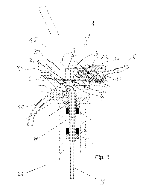
- Fig. 1 illustrates a sectional view of a device in accordance to the
invention;
- Figs. 2 and 3 show enlarged partial sectional views of the device in two
operating
steps;
- Figs. 4 and 5 show the way of application of the device to the neck of a
bottle.
Preferred Embodiment of the Invention
With reference to the attached images, a device 1 for dispensing liquids,
especially wine, from a bottle or a similar container is composed of a body 2
designed to
work with the neck 27 of the bottle and to cause the leakage of liquid from a
blowpipe
10 resulting from the supply of inert gas (eg. nitrogen) under pressure.
Said body 2 comprises a first conduit 3, that is placed transversely and has a
first
opening 22 for the supply of the gas. Two further openings 20 and 21 are
placed along
the conduit 3 for the connection with a second conduit 4 designed to supply
the gas
inside the bottle and, respectively, with a third conduit 5 provided with a
blowpipe 10 for
the dispensing of the liquid.
More specifically, said second conduit 4 protrudes from the body 2 through a
first tube 7 intended to settle inside the neck 27 of the bottle. A second
tube 9 is
advantageously placed culminating on the upper part of the supply blowpipe 10,
passing
through said first tube 7 and extending downward inside the bottle.
A movable cursor 30 within said conduit 3 is subject to the action of a
helical
spring 14 attested between one of its ends and an articulated nipple 11,
mounted at the
opening 22 and provided for the coupling of the supply conduit of the gas 6.
In the
resting position, when the spring 14 is not loaded, the end 32 of the cursor
30 opposite to
that subject to the spring partially protrudes from the opening of the conduit
3 opposite
the opening 22. As will become apparent from the hereinafter, the cursor 30
performs
- 2 -

CA 02848644 2014-03-13
WO 2013/011445
PCT/1B2012/053622
the functions of operating button of the dispensing device.
The sealed connection of the device 1 with the neck of the bottle 27 is
preferably
made (see Figs. 4 and 5) with an expansion system 8, associated with said
first tube 7
and controlled by a lever 15.
In accordance with the invention and as illustrated in Figs. 2 and 3, the
conduit 3
and the cursor 30 are shaped so as to selectively put in communication:
i) said second conduit 4 with the opening 22 in order to cause the release of
the
gas in the bottle and dispensing of the liquid and
ii) said second conduit 4 with said third conduit 5 in order to determine the
leakage of gas through the blowpipe 10 at the end of dispensing.
In a preferred embodiment of the invention, the cursor 30 is provided with a
pair
of 0-rings 23,24 of which the first (23) is substantially placed at the end of
the cursor on
the side of the opening 22 of the gas inlet and is located, with reference to
the flow of
gas injected, always upstream of the openings 20 and 21. The second 0-ring 24
is
instead located at a distance from the first one so that, in the rest position
(see Fig 2), is
located downstream of both openings 20 and 21, while when the cursor 30 is
pushed
against the spring 14 assumes a position between the two openings (see Fig 3).
The inner diameter of the duct 3 is such that, in the rest position, the 0-
rings
23,24 isolate from the gas the part of conduit in which the openings 20 and 21
are
placed. During the dispensing phase, (ie, when the cursor-button 30 is
pressed), since the
diameter of the pipe 3 is greater in correspondence to the opening 22, only
the 0-ring 24
which is now located between the openings 20 and 21 carries the sealing
functions.
The functioning of the device is as follows:
a) in the resting phase (see Fig 2), the gas - fed at the opening 22 through
the
articulated nipple 11 - is confined upstream of the first 0-ring 23 placed at
the end of the
cursor 30; the second conduit 4 and the third conduit 5 are in communication
with each
other via the openings 20 and 21 and the light existing between the outer
surface of the
cursor 30 and the inner surface of the conduit 3; there is no gas flow nor
pressure is
exerted to inside of the bottle and, accordingly, no conduit of the device is
wetted by the
liquid - as happens for example in the device described in EP1352873 - except
obviously
-3 -

CA 02848644 2014-03-13
WO 2013/011445
PCT/1B2012/053622
for the portion of the tube 9 which enters into it;
b) in the loading phase, when the cursor 30 is pushed towards the opening 22
(see Fig 3), the sealing of the first 0-ring 23 lacks and the gas penetrates
inside the
conduit 3 along the outer surface of the cursor 30; as in the same time the
second 0-ring
24 moves between the two openings 20,21 maintaining the sealing, the gas flows
through the opening 20, enters into the second conduit 4 and from here is
introduced,
through the first tube 7, in the bottle; the pressure exerted by the gas
determines the
leakage of liquid through the second tube 9 and the blowpipe 10;
c) in the discharge phase, when at the end of the supply the delivery cursor-
button 30 is released, the two 0-rings 23,24 return to assume the positions at
which
isolate the gas from the conduit portion in which there are the openings 20
and 21 (see
Fig 2); therefore the introduction of the gas and consequently the supply of
the liquid
ceases; the gas contained in the bottle flows first through the pipe 7, the
second conduit 4
and the opening 20 in the opposite direction with respect to the loading phase
and then
along the portion of the pipe 3 between the openings 20 and 21, through this
latter, the
third conduit 5 and the blowpipe 10; the liquid in the tube 9 falls inside the
bottle or,
thanks to the particular conformation of the upper end portion, escapes along
the
blowpipe 10.
Note that, thanks to the operation described above, the device object of the
present invention offers considerable advantages in terms of cleaning of the
conduits.
In fact, the outflow of the gas during discharge through the blowpipe 10
determines the complete cleaning of the same from the residues of the beverage
without
the need to blow in another gas.
In addition to this, the vacuum generated by the emptying of the conduit 9 -
due
to the relapse of the liquid inside the bottle - causes the suction of part of
the inert gas
coming out of the third conduit 5, without that the air can penetrate from the
blowpipe
10. Therefore, it is also obtained that also the conduit 9 is completely
cleaned of residues
and there is no risk of oxidation of the liquid.
An empty bottle can also be easily and quickly replaced with a full new one by
using the control lever 15 of the expansion system 8. Since in the resting
phase the
- 4 -

CA 02848644 2014-03-13
WO 2013/011445
PCT/1B2012/053622
internal conduits are not filled by the liquid, once disengaged from the neck
of the bottle,
the device can be completely immersed in a washing bath.
The example described is given by way of example, but it is understood that
equivalent variants can be conceived without departing from the scope of the
invention.
-5 -

Representative Drawing
A single figure which represents the drawing illustrating the invention.
Administrative Status

2024-08-01:As part of the Next Generation Patents (NGP) transition, the Canadian Patents Database (CPD) now contains a more detailed Event History, which replicates the Event Log of our new back-office solution.

Please note that "Inactive:" events refers to events no longer in use in our new back-office solution.

For a clearer understanding of the status of the application/patent presented on this page, the site Disclaimer , as well as the definitions for Patent , Event History , Maintenance Fee  and Payment History  should be consulted.

Event History

Description Date
Application Not Reinstated by Deadline 2016-07-18
Time Limit for Reversal Expired 2016-07-18
Deemed Abandoned - Failure to Respond to Maintenance Fee Notice 2015-07-16
Inactive: Cover page published 2014-04-29
Inactive: Notice - National entry - No RFE 2014-04-17
Inactive: IPC assigned 2014-04-15
Inactive: First IPC assigned 2014-04-15
Application Received - PCT 2014-04-15
National Entry Requirements Determined Compliant 2014-03-13
Application Published (Open to Public Inspection) 2013-01-24

Abandonment History

Abandonment Date Reason Reinstatement Date
2015-07-16

Maintenance Fee

The last payment was received on 2014-07-10

Note : If the full payment has not been received on or before the date indicated, a further fee may be required which may be one of the following

  • the reinstatement fee;
  • the late payment fee; or
  • additional fee to reverse deemed expiry.

Please refer to the CIPO Patent Fees web page to see all current fee amounts.

Fee History

Fee Type Anniversary Year Due Date Paid Date
Basic national fee - standard 2014-03-13
Reinstatement (national entry) 2014-03-13
MF (application, 2nd anniv.) - standard 02 2014-07-16 2014-07-10
Owners on Record

Note: Records showing the ownership history in alphabetical order.

Current Owners on Record
FRANCESCA BARNINI
Past Owners on Record
None
Past Owners that do not appear in the "Owners on Record" listing will appear in other documentation within the application.
Documents

To view selected files, please enter reCAPTCHA code :


To view images, click a link in the Document Description column. To download the documents, select one or more checkboxes in the first column and then click the "Download Selected in PDF format (Zip Archive)" or the "Download Selected as Single PDF" button.

List of published and non-published patent-specific documents on the CPD .

If you have any difficulty accessing content, you can call the Client Service Centre at 1-866-997-1936 or send them an e-mail at CIPO Client Service Centre.


Document
Description 
Date
(yyyy-mm-dd) 
Number of pages   Size of Image (KB) 
Drawings 2014-03-13 4 190
Description 2014-03-13 5 194
Abstract 2014-03-13 1 75
Claims 2014-03-13 1 38
Representative drawing 2014-03-13 1 49
Cover Page 2014-04-29 2 67
Reminder of maintenance fee due 2014-04-17 1 111
Notice of National Entry 2014-04-17 1 192
Courtesy - Abandonment Letter (Maintenance Fee) 2015-09-10 1 171
PCT 2014-03-13 10 325