Note: Descriptions are shown in the official language in which they were submitted.
1
METHOD AND APPARATUS FOR PREVENTING BUILDUP OF TWINE AND NETWRAP ON THE
ROTOR OF A BALE PROCESSOR
Technical Field
[0001] This invention relates generally to bale processors and more
particularly to a
method and apparatus for preventing the buildup of twine and/or netwrap on the
rotor of a
bale processor.
Background
[0002] Bale processors are devices used to spread the content of bales of
forage in a
controlled way for reasons such as mulching or feeding livestock. Examples of
bale processors
are shown in U.S. Patent Nos. 6,708,911 to Patterson et al., 6,711,824 to
Hruska, 6,578,784 to
Lischynski et al., 6,886,763 to Lepage et al., 7,581,691 to Helmeczi et al.
and Published U.S.
Patent Application No. 2006/0086857 to Lepage et al..
[0003] These bale processors typically have a cylindrical rotor with
hammers or flails
pivotally attached thereto along the outside of the rotor. As the rotor
rotates, the
hammers/flails hit the outside of a bale, causing those outside portions of
the bale to be
separated from the bale and then thrown out of the bale processor to the
ground.
CA 2848959 2018-02-21
CA 02848959 2014-03-14
WO 2013/066287 PCT/US2011/058514
2
[0004] Since bales of forage typically have twine or netwrap on the outside
thereof for holding them together, this twine/netwrap is the first thing the
hammers/flails hit when a new bale is introduced into the hopper of a bale
processor. But instead of throwing all of the twine/netwrap out of the bale
processor, a significant amount of the twine/netwrap wraps around the rotor
and
stays there between adjacent hammers/flails. The more the twine/netwrap
builds up on the rotor, the less effective the hammers/flails are in removing
forage from the outside of the bale.
[0005] This problem of the twine/netwrap was recognized in U.S. Patent No.
6,886,763 to Lepage et al and was dealt with by periodically using a specially
designed spear shaped knife to cut the twine/netwrap from the rotor. While
this
is one way to deal with the problem, it requires stopping /starting and manual
labor to use the knife to clean the rotor.
[0006] Accordingly, a more efficient and automatic method and apparatus
for preventing twine/netwrap from building up on the rotor of a bale processor
is
needed.
Brief Description of the Drawings
100071 The above needs are at least partially met through provision of the
method and apparatus described in the following detailed description,
particularly
when studied in conjunction with the drawings, wherein:
[0008] FIG. 1 is a top plan view of a preferred embodiment of the bale
processor of the present invention;
[0009] FIG. 2 is a perspective view of the bale processor of Fig. 1;
CA 02848959 2014-03-14
WO 2013/066287
PCT/US2011/058514
[0010] FIG. 3 is a rear elevational view of the bale processor of Figs. 1
and 2;
[0011] FIG. 4 is a side elevational view of the bale processor of the
present
invention;
[0012] FIG. 5 is a rear elevational schematic view with the rear sheet
metal
panel of the hopper removed to show the working parts inside of one
embodiment of the slug bars/depth control bars in one pivotal position thereto
illustrating the adjustment arm in the lowest position, rotated about the
adjustment pivot, which causes the slug bar to rotate clockwise as the
adjustment arm is being moved downward, pivoting about the slug bar pivot and
in this position the upper surface of the slug bar holds the bale away from
the
rotor at the maximum separation distance, where the distance from the
centerline of the rotor to the upper surface of the slug bar is at a maximum;
[0013] FIG. 6 is a rear elevational view like Fig. 5 but showing the slug
bars/depth control bars in another pivotal position thereof where the
hammers/flails on the rotor stick up farther above the top of the depth
control
bars so as to take bigger chunks of hay from the bale than in the position
shown
in Fig. 5, Figs. 5 and 6 both showing how close the pointed part of the lower
part
of the depth control bar is to the outer surface of the cylindrical rotor,
Fig. 6 also
illustrating the adjustment arm in the highest position, rotated about the
adjustment pivot, which causes the slug bar to rotate, counter-clockwise as
the
adjustment arm is being moved upward, pivoting about the slug bar pivot and in
this position the upper surface of the slug bar holds the bale away from the
rotor
at the minimum separation distance, i.e. where the distance from the
centerline
of the rotor to the upper surface of the slug bar is at a minimum;
CA 02848959 2014-03-14
WO 2013/066287
PCT/US2011/058514
4
[0014] FIG. 7 is a front schematic view of the hopper with the front sheet
metal part of the hopper removed so as to show the position of other depth
control bars in the same position as they are shown in Fig. 6;
[0015] FIG. 8 is a front schematic view through the center of the hopper
that is quite similar to the Fig. 7 view;
[0016] Fig. 9 is a view like Fig. 7, but showing a depth control bar of a
different configuration as shown in Figs. 10 and 14;
[0017] Fig. 10 is a view like Fig. 8, but with the depth control bar of
Figs. 7
and 14;
[0018] Fig. 11 is a view like Figs. 7/9, but showing a depth control bar of
a
different configuration like that shown in Fig. 15;
[0019] Fig. 12 is a view like Fig. 8/10, but with the depth control bar of
Figs.
11 and 15;
[0020] Fig. 13 is a side elevational view of the depth control bar of the
embodiment of Figs. 1-8;
[0021] Fig. 14 is a side elevational view of the depth control bar of the
embodiment of Figs. 9 and 10; and
[0022] Fig. 15 is a side elevational view of the depth control bar of the
embodiment of Figs. 11 and 12.
[00231 Fig. 16 is a front schematic view through the center of the hopper
that is quite similar to the Fig. 8 view;
[00241 Fig. 17 is is a front schematic view through the center of the
hopper
that is quite similar to the Fig. 16 view only it shows an alternate
embodiment
CA 02848959 2014-03-14
WO 2013/066287
PCT/US2011/058514
using rotors to rotate the bale instead of a chain conveyor like the earlier
embodiments of Figs. 1-16;
100251 Fig. 18 shows an embodiment similar to the embodiment of Figs. 10-
12, except instead of using the depth control bars to keep the netwrap/twine
from building up on the rotor/drum separate members disposed between the
hammers 14f of the rotor/drum serve that purpose independently of the position
of the depth control bars;
100261 Fig. 19 shows an embodiment similar to the embodiment of Figs. 10-
12, except (1) instead of using the depth control bars to keep the
netwrap/twine
from building up on the rotor/drum separate members disposed between the
hammers 14f of the rotor/drum serve that purpose independently of the position
of the depth control bars and (2) the bale is rotated using the rotors that
are also
shown in Fig. 17 instead of the chain conveyor of the earlier shown
embodiments;
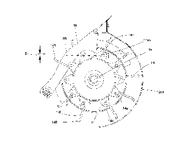
100271 Fig. 20 shows the spacing between the rotor and the rotor/drum;
[0028] Fig. 21 shows that the hammers 14f do not need to be mounted on a
rotor/drum but can be just attached to the end of structural elements 14s that
are rotatably mounted about shaft 15;
100291 Fig. 21a is a view of the rotor taken along line 21a-21a- of Fig.
21;
[00301 Fig. 22 shows an alternate embodiment wherein a sickle blade
section is rigidly attached to the outside of the drum for helping to
facilitate
cutting of the netwrap/twine;
CA 02848959 2014-03-14
W02613/066287 6
PCT/US2011/058514
[00311 Fig. 23 is an enlarged top elevational view of the embodiment of
Fig.
22 showing the sickle blade section under a depth control bar and also showing
two of the many spaced apart flails on the flail rotor; and
[00321 Fig. 24 is a perspective view of the embodiment of Figs. 22 and 23
showing the sickle blade section, one of the depth control bars and portions
of
the rotor with the flails attached thereto.
[00331 Elements in the figures are illustrated for simplicity and clarity
and
have not necessarily been drawn to scale. For example, the dimensions and/or
relative positioning of some of the elements in the figures may be exaggerated
relative to other elements to help to improve understanding of various
embodiments of the present invention. Also, common but well-understood
elements that are useful or necessary in a commercially feasible embodiment
are
often not depicted in order to facilitate a less obstructed view of these
various
embodiments of the present invention. Certain actions and/or steps may be
described or depicted in a particular order of occurrence while those skilled
in the
art will understand that such specificity with respect to sequence is not
actually
required. The terms and expressions used herein have the ordinary technical
meaning as is accorded to such terms and expressions by persons skilled in the
technical field as set forth above except where different specific meanings
have
otherwise been set forth herein.
Detailed Description
[00341 Referring now to the drawings, wherein like reference numerals
indicate identical or similar parts throughout the several views, Figs. 1 and
2 show
7
a bale processor 10 constructed in accordance with a preferred embodiment of
the invention.
[0035] The
bale processor 10 has a frame 11 as shown in Fig. 3, connecting a hopper 12
to the frame 11 for receiving a bale (not shown) to be processed. The hopper
12 has two side
walls 12a/12b and two end walls, 12f/12r arranged to define an open top
through which the bale
is loaded when a pivoted top 12t is in the open position as shown in Fig. 2.
The two side walls
12a/12b converge inwardly and downwardly to a lower disintegration area 13
(See Fig. 7). A flail
rotor 14 is mounted in the disintegration area and rotatable about an axis 15,
extending generally
along the side wall 12b and transverse to the end walls 12f/12r. The flails 14
are preferably flails
like those shown in Fig. 24 with the outer cutting edge leading the rest of
the flail when it rotates
because this type of flail tend to throw the material, which action is desired
in a bale processor.
The rotor 14 and flails 14f of this invention are like those disclosed in U.S.
Patent No. 7,581,691,
column 1, starting at line 45. An example of such a typical flail
disintegrator for a bale processor
is illustrated in Figs. 1-24 and is also described in U.S. Pat. No. 6,109,553
issued on Aug. 29, 2000
to Hruska. The flail disintegrator 11 includes a cylindrical shaped rotor 14
having a substantially
circular cross-section. A number of flails 14f are pivotally mounted on the
flail rotor 14. The flails
14f are intermittently spaced along the length and symmetrically spaced around
the
circumference of the rotor 14 for balance. Each flail 14f is made from a solid
metal bar having a
rectangular cross-section and, in this example, is reverse bent at two points.
One end of each flail
14f is welded to a hollow cylindrical section for pivotally mounting by a bolt
to a support or tab 6
that is welded to the rotor 14. The other, radially outer, end of flail 114f
is beveled to provide a
cutting or tearing edge.
CA 2848959 2018-02-21
8
[0036] Fig. 7 shows a portion of a chain conveyor 16 positioned in the
hopper 12 to rotate
the bale 17 around an axis 17a (Fig. 7) that is generally parallel to the
flail rotor axis 15. Chain
conveyor 16 is powered by hydrostatically powered sprocket 16ds and idler
sprocket 16is that
are positioned outside and below the hopper 12. Drive members 16a, supported
by plate 16p
and wear strips 16w, and attached to chains 16c, engage the bale, at the
bottom of the hopper
12. Movement of the drive members 16a in the direction of arrow 16d result in
rotation of the
bale in direction 17d. The flail rotor 14 rotates in a direction 14d. The
direction of movement of
chain conveyor 16 can be reversed as may be required to accommodate variations
in bale shape.
Wear strips 16w are supported on metal plates 16p disposed at the bottom of
the hopper 12.
[0037] The flail rotor 14 providing an outer support surface with a
plurality of flails 14f
pivotally mounted thereon along axes 14p for movement therewith around the
flail rotor axis 15
for engaging the bale 17 and removing material from the outside thereof due to
the flails 14f
above the spacer bars 18 coming in contact with the outer part of the bale 17.
Some of the flails
14f are spaced apart along the flail rotor axis 15 as can best be seen in Fig.
1. The rotor 14 is like
U.S. Patent No. 7,581,691 to Helmeczi et al., and the flails 14f are
preferably cup shaped like
those shown in U.S. Patent No. 7,581,691 to Helmeczi et al.,.
[0038] One of the side walls 12a has a discharge opening 12do at the
disintegration area
13 for discharge of the material removed from the bale 17 by
CA 2848959 2018-02-21
CA 02848959 2014-03-14
WO 2013/066287 PCT/US2011/058514
9
the flail rotor flails 14f from the disintegration area 13. The discharge
opening
12do has a door 12d which can optionally be held closed with latches 12L when
the bale processor 10 is not in use.
100391 A plurality of depth control bars/slugs 18 are pivotally attached at
the
top end by bolts 18c, the depth control bars/slugs 18 being disposed between
adjacent flails 14f for controlling the distance that a radially outer end of
the flails
14f extend into the outer surface of the bale 17 as can be seen by comparing
the
different distance that the flails 14f extend above the depth control bars 18
in Fig.
as compared to how far the flails 14f extend above the depth control bars 18
in
Fig. 6. Attention is directed to the fact that the changes in the pivotal
position of
the depth control bars 18 between Figs. 5 and 6 are changed by moving the
control/slug bar adjustment arm 19 about its pivot axis 19a, thereby pivoting
the
depth control bars 18 about pivot point axis 18a and moving the bottom of
depth
control bars 18 at bar 18c in slot 18s (Fig. 7). A pin 20 is used to lock the
control
bar adjustment arm 19 in one of five positions corresponding to the holes 21a
in
member 21 which is fixed with respect to the frame 11. Notice that in Fig. 5
the
pin 20 is in the lowest hole 21a of member 20 and that in Fig. 6 the pin 20 is
in the
top hole 21a of the member 21.
[0040] While the rotor 14 is shown rotating in a counterclockwise direction
in Figs. 5-12, it could rotate in an opposite direction, for example if it was
desired
to throw the extracted parts of the bale out the other side of the bale
processor
instead of out the side shown.
[0041] The depth control bars 18 having a side closest to the flail rotor
axis
18b and a side 18t farthest from the flail rotor axis 15. The depth control
bars 18
CA 02848959 2014-03-14
WO 2013/066287 PCT/US2011/058514
have a first position close to the outer support surface of the flail rotor 14
that the
plurality of flails 14f are mounted on and the depth control bars 18 have a
second
position farther from the outer support surface of the flail rotor 14 that the
plurality of flails are mounted on whereby the side 18b of the depth control
bars
18 closest to the outer support surface of the flail rotor 14 tends to prevent
the
buildup of twine and/or netwrap on such outer support surface of flail rotor
14.
100421 Looking to Figs. 5-8, it is noted that the end 18h of a hook shaped
portion of depth control bars 18 is closest to the outer surface of the flail
rotor 14,
so that any twine or netwrap that might tend to build up above point 18h on
the
outer surface of rotor 14 hits the hook shaped portion at 18h and is cut into
pieces that quickly exit through the discharge opening 12 with the other
forage
from the bale 17. In actual operation, it turns out somewhat surprisingly that
most twine or netwrap that is between the point 18h and the outer part of the
rotor 14 tends to be shed from the rotor 14 as well.
[0043] The new designed depth control bar is designed to run closer to the
skin of processing rotor between 0 .10-1.75 inches for a functional range,
noting
that not as much net/twine would be shed in the upper range. The optimum
appears to be in the .25-1.00" range with 0.75 appearing to be ideal. This
creates
a catch point between end 18h of the depth control bars 18 for the material on
the rotor 14 and causes netwrap or twine between the two parts to be ejected
with the processed material. The geometry of the mounting points is such that
the catch point between point 18a and the rotor 14 remains constant through
the
range of depth of cut adjustment.
CA 02848959 2014-03-14
WO 2013/066287
PCT/US2011/058514
11
[0044] Figs 5 and 6 are schematic views. They illustrate the slug bar
adjustment arm and a slug bar as they are positioned relative to the rotor
with
the flails extended as they would be while the rotor is spinning.
[00451 Fig 5 illustrates the adjustment arm 19 in the lowest position,
rotated about the adjustment pivot 19a, which causes the slug bar 18 to rotate
clockwise as the adjustment arm 19 is being moved downward, pivoting the slug
bar 18 about the slug bar pivot 18a. In this position the upper surface 18t of
the
slug bar 18 holds the bale 17 away from the rotor 14 at the maximum separation
distance, where the distance from the centerline 15 of the rotor 14 to the
upper
surface of the slug bar 18 is at a maximum.
[0046] Fig 6 illustrates the adjustment arm 19 in the highest position,
rotated about the adjustment pivot 19a, which causes the slug bar 18 to
rotate,
counter-clockwise as the adjustment arm 19 is being moved upward, pivoting
about the slug bar pivot 18a. In this position the upper surface of the slug
bar 18
holds the bale 17 away from the rotor 14 at the minimum separation distance,
where the distance from the centerline 15 of the rotor 14 to the upper surface
18t of the slug bar 18 is at a minimum.
[0047] In both positions the inner surface of the slug bar 18 includes a
feature, which in these figures is a hook-like structure 18h that is
maintained at a
substantially consistent spacing from the rotor 14 regardless of the pivoted
position of the slug bar 18. This characteristic is important for the novel
function
of the slug bar 18, in keeping wrap material (netwrap or twine) from building-
up
excessively on the rotor 14.
CA 02848959 2014-03-14
WO 2013/066287 12 PCT/US2011/058514
[0048] The embodiment 100 of Figs. 9, 10 and 14 works just like the
embodiment of Figs. 1-8 and 13, except the shape of the depth control bars 118
in
the embodiment of Figs. 9, 10 and 14 are different than the depth control bars
18
of Figs. 1-8 and 13. It is approximately point 118h that corresponds to point
18h in
the embodiment 10 of Figs. 1-8.
[0049] The embodiment 200 of Figs. 11, 12 and 15 works just like the
embodiment of Figs. 1-8 and 13, except the shape of the depth control bars 218
in
the embodiment of Figs. 9, 10 and 14 are different than the depth control bars
18
of Figs. 1-8 and 13. It is approximately point 218h that corresponds to point
18h in
the embodiment 10 of Figs. 1-8.
[0050] Fig. 16 is a front schematic view through the center of the hopper
12.
It is noted that the end 18h of a hook shaped portion of depth control bars 18
is
closest to the outer surface of the flail rotor/rotor 14, so that any twine or
netwrap that might tend to build up above point 18h on the outer surface of
rotor
14 hits the hook shaped portion at 18h and is cut into pieces that quickly
exit
through the discharge opening 12 with the other forage from the bale 17. In
actual operation, it turns out somewhat surprisingly that most twine or
netwrap
that is between the point 18h and the outer part of the rotor 14 tends to be
shed
from the rotor 14 as well.
[0051] Fig. 17 is a front schematic view through the center of the hopper
12
that is quite similar to the Fig. 16 view but it shows an alternate embodiment
using rotors 160a and 160b to rotate the bale 17 about axis 17a in the
direction
17d instead of using a chain conveyor like the earlier embodiments of Figs. 1-
16;
CA 02848959 2014-03-14
WO 2013/066287 PCT/US2011/058514
13
[0052] Fig. 18 shows an embodiment similar to the embodiment of Figs. 10-
12, except instead of using the depth control bars 18, 118, 218 to keep the
netwrap/twine from building up on the rotor/drum separate members 300
disposed between the hammers 14f of the rotor/drum serve that purpose
independently of the position of the depth control bars.
[0053] Fig. 19 shows an embodiment similar to the embodiment of Figs. 10-
12, except (1) instead of using the depth control bars 18, 118, 218 to keep
the
netwrap/twine from building up on the rotor/drum separate members 300
disposed between the hammers 14f of the rotor/drum serve that purpose
independently of the position of the depth control bars and (2) the bale is
rotated
using the rotors 160a and 160b that are also shown in Fig. 17 instead of the
chain
conveyor of the earlier shown embodiments. The spacing S between the end
300h and the outer circumference of the rotor/drum 14 is preferably between
0.5
and 1.0 inches, 0.75 inches being found to be ideal under most circumstances.
Member 300 can be made to be adjustable so it can be adjusted in the field for
varying conditions.
[0054] Fig. 20 shows the spacing between the rotor and the rotor/drum
which can be set permanently or can be adjustable.
[0055] Fig. 21 shows that the hammers 14f do not need to be mounted on a
rotor/drum but can be just attached to the end of crossing structural elements
14s that are rotatably mounted about shaft 15. The spacing S is shown as the
distance between the outer periphery of the circular path made by the outer
ends
of structural members 14s and the depth control bars point 218h.
CA 02848959 2014-03-14
WO 2013/066287 14
PCT/US2011/058514
[0056] Distance 14z is the outside surface of the drum 14 in Figs. 1-20.
14csr
is the cutting surface of rotation in Figs. 20 and 21.
100571 Distance 14zb is the horizontal surface bars that connect adjacent
ends of rotor members 14s in Fig. 21.
[0058] Also shown in dashed lines is optional engagement members 300
that can be in addition to using the depth control bars 218 to shed
netwrap/twine
or instead of using the depth control bars 218 to be close enough to the rotor
14s
to keep the netwrap/twine from building up on rotor part 15. The optional
engagement members 300 can, if desired, extend radially inwardly enough to
almost, but not quite, touch the outside of rotor shaft 15.
[0059] Referring now to another embodiment in Figs. 22-23 a sickle blade
section 14sb is rigidly attached to the outside of the drum 14 for helping to
facilitate cutting of the netwrap/twine. The spacing S between the sickle
blade
14sb and the point 18h on depth control bar 18 is between 0 .10-1.75 inches.
[0060] In Figs. 23 and 24 the sickle blade section14sb is shown under a
depth control bar 18 and also show two of the many spaced apart flails 14f on
the
flail rotor 14, noting that the flails 14f have a pivoting part 14fp and a
sharpened
tip 14ft. A bolt 140 extends through the pivoting part 14fp and through
flanges
141 which are welded to the drum 14.
[0061] Those skilled in the art will recognize that a wide variety of
modifications, alterations, and combinations can be made with respect to the
above described embodiments without departing from the spirit and scope of the
invention, and that such modifications, alterations, and combinations are to
be
CA 02848959 2014-03-14
WO 2013/066287
PCT/US2011/058514
viewed as being within the ambit of the inventive concept as expressed by the
attached claims.