Note: Descriptions are shown in the official language in which they were submitted.
CA 02849047 2014-03-18
WO 2013/057009 PCT/EP2012/069989
- 1 ¨
Process and apparatus for dedusting a vapor gas mixture
The present invention is directed to a process and an apparatus for dedusting
a
dust laden vapor gas mixture obtained by the pyrolysis of preferably solid
mate-
rial containing hydrocarbons, in particular oil shale.
In order to obtain oil from oil shale, the oil shale is directly heated by a
hot heat
carrier (ash) to a temperature of about 500 C in a rotary kiln. Hereby, oil
evapo-
1 0 rates from the oil shale forming the so called vapor gas mixture (VGM).
The
vapor gas mixture (a gas containing also fine particles) is then quenched in a
condensation unit for winning the oil. This oil contains particulate material
(fines), which are very hard to separate from the oil and prevent a further im-
provement of its quality due to e.g. catalyst deactivation. Traditionally,
such
separation has been done by using a scrubber. The dust particles collected by
droplets produced in the scrubber can be found in the cooled oil at the
scrubber
bottom. If a venturi scrubber is used, there is a high pressure loss, which re-
quires corresponding high pressures in the rotary kiln and thereby increases
the
equipment costs. Further, dust laden heavy oil is recycled to the pyrolysis
zone
and thus cannot be used directly as a product. The removal of fine dust
particles
from oil is a very expensive procedure and a technical challenge which has not
yet been completely solved.
According to US patent 4 548 702 A raw oil shale is fed into a specified
surface
retort followed by solid heat carrier material at 1000 to 1400 C. The
withdrawn
product stream is partially dedusted in a cyclone or filter. Further dust is
re-
moved in a fractionator, scrubber or quench tower. The oil fraction then is
fed
into a hydroprocessor followed by a catalyst and hydroprocessing gas. The dust
removed from the oil fraction and the water stream of sludge containing the
dust
CA 02849047 2014-07-14
2
is used together with the retorted shale as a fuel to heat the heat carrier
material
and to retort the raw oil.
From document DE 196 11 119 C2 a process for purifying hot waste gases
containing dust and tar and obtained during the production of calcium carbide
in
an arc furnace is known, which comprises dedusting the waste gas at 200 to
900 C using a ceramic filter and subsequently removing the tar at 50 to 200 C
using a gas scrubber or electro filter. At such temperatures substantial
condensation of heavier oil fractions would have to be expected so that this
process is not suitable for dedusting VGM.
It is the object of the present invention to provide for a more efficient
production of
oil from oil shale or the like. In particular, the removal of dust from the
vapor gas
mixture obtained by pyrolysis shall be optimized.
In accordance to a particular embodiment, the invention relates to a process
for
dedusting a dust laden vapor gas mixture (VGM) obtained by the pyrolysis of a
material containing hydrocarbons, in particular oil shale, wherein the dust
laden
VGM is treated in a dry electrostatic precipitator at a temperature of 380 to
480 C
to separate dust from the VGM and wherein subsequent to the dust removal in
the electrostatic precipitator the VGM is cooled and directed to at least one
further
electrostatic precipitator where it is treated at a temperature suitable to
separate a
desired fraction of the oil.
The electrostatic precipitator is operated in a dry state at a temperature
above the
condensation temperature of the oil so that the dust is separated without any
condensation of oil. This substantially reduces the contamination of the
product
(pyrolysis oil). This is particularly important for the subsequent oil
upgrading
requiring oils having very low dust loads.
CA 02849047 2015-08-12
2a
In accordance to another particular embodiment, the invention relates to an
apparatus for dedusting a vapor gas mixture (VGM) obtained by the pyrolysis of
a
material containing hydrocarbons, and for performing a process according to
the
present invention and as described above, comprising at least one
electrostatic
precipitator operating at 380 to 480 C and a first cooler provided downstream
of
the at least one electrostatic precipitator, characterized in that a
rectification
means (2) is provided downstream of the at least one electrostatic
precipitator,
wherein the rectification means (2) comprises one or more electrostatic
precipitator(s) each in combination with another cooler for adjusting the
temperature of the VGM entering the respective electrostatic precipitator.
An electrostatic precipitator (ESP) is a particulate collection device that
removes
particles from the VGM using the force of induced electrostatic charge. It,
thereby,
is a highly efficient filtration device that minimally impedes the flow of
gases
through the precipitator and can easily remove fine dust particles from the
VGM.
For implementing the present invention, the electrostatic precipitator may be
a
tube, plate or chamber precipitator, wherein a tube precipitator is preferred.
CA 02849047 2014-03-18
WO 2013/057009 PCT/EP2012/069989
- 3 -
It should be noted that instead of oil shale other hydrocarbon containing
materi-
als, such as oil sand, biomass, plastics, oil wastes, waste oils, animal fat
con-
taining materials, or vegetable oil containing materials may be used for the
process of the present invention as long as a vapor gas mixture containing oil
can be produced by the pyrolysis of said material. Preferably, the hydrocarbon
material contains 8 to 80 "Yo by weight of hydrocarbons.
According to a preferred embodiment of the present invention the vapor gas
mixture comprises 40 to 90% by weight of 05+ hydrocarbons, 4.5 to 40% by
weight of 04- hydrocarbons, 0.01 to 30% by weight of non condensable fractions
(i.e. gases like H2, N2, H2S, SO2, NO, etc.) and 5 to 30% by weight of water.
Preferably, the composition of the vapor gas mixture is as follows: 55 to 85%
by
weight of 05+ hydrocarbons, 7 to 25 "Yo by weight of 04- hydrocarbons, 0.1 to
15% by weight of non condensable fractions and 7 to 20% by weight of water,
more preferably the composition of the vapor gas mixture is as follows 60 to
80% by weight of 05+ hydrocarbons, 13 to 22% by weight of 04- hydrocarbons,
0.3 to 10% by weight of non condensable fractions and 7 to 15% by weight of
water.
The dust content of the dust laden vapor gas mixture preferably is 3 to 300
g/Nm3, more preferably 20 to 150 g/Nm3.
In order to improve the dust separation, at least two successive electrostatic
precipitators are provided, in which the dust laden vapor gas mixture is
treated
at a temperature of 380 to 480 C.
As the condensation of oil is substantially avoided, the dust separated in the
electrostatic precipitator can be mechanically removed by rapping or vibrating
the precipitator.
CA 02849047 2014-03-18
WO 2013/057009 PCT/EP2012/069989
- 4 -
It is within the present invention to cool the vapor gas mixture to a
temperature
of 310 to 360 C subsequent to the treatment in the electrostatic precipitator.
Thereby, an extra heavy oil stream can be separated from the VGM by conden-
sation which has an ash content of < 80 ppm and can be used as a recycle
stream or as product. If the VGM is cooled to room temperature (about 23 C)
all
oil fractions of the pyrolysis oil can be condensed.
The cooling preferably is done by indirect cooling with air or water or by
injecting
additional oil (direct cooling).
In a quite preferred embodiment of the present invention, subsequent to the
cooling step the VGM is treated in a wet electrostatic precipitator at the
tempera-
ture defined by the cooler, i.e. between 310 and 360 C, or at another tempera-
ture suitable to separate the desired oil fraction. In the wet electrostatic
precipi-
tator further portions of the heavy or other oil fraction may be separated
from the
VGM and recycled or used as a product.
Subsequent to the dust removal in the electrostatic precipitator, the cleaned
VGM is treated in a rectification means to separate various desired oil
fractions.
In a preferred embodiment, the cleaned VGM is directed to at least one further
electrostatic precipitator where it is treated at a temperature suitable to
separate
a desired fraction of the oil. Several electrostatic precipitators operating
at vari-
ous temperatures may be successively provided to obtain the desired oil frac-
tions based on their condensation temperature.
Thereby, different low dust product oil fractions are obtained, comprising
less
than 30 ppm of dust.
CA 02849047 2014-03-18
WO 2013/057009 PCT/EP2012/069989
- 5 -
The invention also is directed to an apparatus for dedusting a vapor gas
mixture
obtained by the pyrolysis of a material containing 8 to 80% by weight of hydro-
carbons, in particular oil shale, which is suited for performing a process as
de-
scribed above. The apparatus comprises at least one electrostatic precipitator
operating at 380 to 480 C.
Preferably, a cooler is provided downstream of the electrostatic precipitator.
In a
further embodiment, a wet electrostatic precipitator may be provided down-
stream of the cooler.
Downstream of the dry and/or wet electrostatic precipitator a suitable
rectifica-
tion means may be provided for separating various oil fractions.
In a preferred embodiment the rectification means comprises one or more elec-
trostatic precipitator(s) each in combination with a cooler for adjusting the
tem-
perature of the VGM entering the respective precipitator to a value suitable
to
separate (condense) the desired oil fraction.
The invention now will be described in more detail on the basis of preferred
embodiments and the drawing.
In the drawing:
Fig. 1 is a schematic view of an apparatus according to a first
embodi-
ment of the present invention,
Fig. 2 is a schematic view of an apparatus according to a second
embod-
iment of the present invention and
CA 02849047 2014-03-18
WO 2013/057009 PCT/EP2012/069989
¨ 6 ¨
Fig. 3 is a schematic view of an apparatus according to a third
embodi-
ment of the present invention.
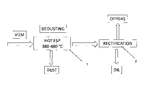
In the first embodiment of the present invention as shown in Fig. 1 depicting
the
basic concept of the invention, a vapor gas mixture (VGM) obtained by the
pyrolysis of oil shale or any other suitable material and having a dust
content of
3 to 300g/Nm3 is introduced into a hot electrostatic precipitator 1 operated
at a
temperature of 3800 to 480 C. In the electrostatic precipitator the dust is
sepa-
rated from the oil vapor and settles on the tube walls from where it can be re-
moved by rattling/rapping.
The cleaned (dedusted) oil vapor then is conducted to a rectification means 2,
e.g. a standard rectification column, for separating various product oil
fractions
based on their condensation temperature. The oil fractions may be obtained by
standard processes and have a dust content of < 30 ppm.
In the somewhat more detailed embodiment according to Fig. 2 the VGM ob-
tained by oil shale pyrolysis in a rotary kiln 3 or any other suitable
pyrolysis
device enters a first electrostatic precipitator 4.1. As shown in Fig. 2, two
elec-
trostatic precipitators 4.1 and 4.2 are provided in series and successively
passed by the VGM. Both electrostatic precipitators 4.1 and 4.2 are operated
as
dry precipitators at a temperature of 380 to 480 C, preferably 400 to 460 C,
which basically corresponds to the exit temperature of the rotary kiln 3 and
is
well above the condensation temperature of the oil so that a condensation even
of heavy oil fractions can be avoided. The temperature of the electrostatic
pre-
cipitators 4.1 and 4.2 is maintained by respective electrical trace heaters
5.1 and
5.2 or any other suitable heating device. By means of electrodes 6.1 and 6.2 a
suitable voltage of e.g. 5 kV to 120 kV, preferably 10 kV to 30kV is provided
to
separate the dust which is withdrawn through lines 7.
CA 02849047 2014-03-18
WO 2013/057009 PCT/EP2012/069989
- 7 -
Subsequent to the electrostatic precipitators 4 a cooler 8 is provided to cool
the
dedusted VGM to a temperature close to the ambient temperature, in particular
about 23 C before the VGM enters a wet electrostatic precipitator 9 also
operat-
ing at this temperature. The wet precipitator is operated at a temperature
below
the condensation temperature of hydrocarbons contained in the gas. As the
VGM is cooled, small condensed droplets are formed which are dispersed as
aerosols in the gas stream. The main part of the condensed droplets is
collected
at the cooler surface, the droplets remaining in the gas stream, being small
enough, pass through the cooler. After charging them via the electrode, they
are
separated at the counter-electrode. Thereby, the wet electrostatic
precipitator
precipitates all wet/condensed components from the gas. In the wet electrostat-
ic precipitator 9 the generated oil aerosols are separated so that oil can be
withdrawn through line 10. As there already is some condensation of extra
heavy oil fractions in the cooler 8 this condensate can also be withdrawn and
combined with the pyrolysis oil withdrawn from the wet electrostatic
precipitator
9.
In the embodiment according to Fig. 3 an additional cooler 11 is provided be-
tween the two electrostatic precipitators 4.1 and 4.2.
In the first electrostatic precipitator 4.1 the dust is separated and
withdrawn. As
in the second embodiment, the electrostatic precipitator 4.1 is operated at a
temperature of 380 to 480 C, preferably 400 to 460 C. The VGM then enters the
cooler 11, in which it is preferably indirectly cooled with air to a
temperature of
310 to 360 C. Extra heavy fractions of the oil may be condensed and withdrawn
through line 12. In this embodiment the second electrostatic precipitator 4.2
is
operated as a wet electrostatic precipitator at a lower temperature between
310
and 360 C basically corresponding to the exit temperature of the cooler 11.
CA 02849047 2014-03-18
WO 2013/057009 PCT/EP2012/069989
¨ 8 -
After the second electrostatic precipitator 4.2 an additional cooler 8,
preferably
indirectly cooled with water, is provided which cools the VGM to the ambient
temperature, preferably about 23 C, prior to introducing it into the wet
electro-
static precipitator 9 where the pyrolysis oil is separated and may be
withdrawn
as product or for further processing. The offgas is discharged through line
13.
The invention will now be further explained by way of examples which are based
on research plants according to Fig. 2 and 3, respectively.
Example 1 (based on Fig. 2)
Table 1: Vapor gas mixture VGM
VGM at 430 C before dedusting
Composition of VGM before electrostatic precipitator (4)
H2 3,4 g/h
Methane 16 g/h
CO 28 g/h
CO2 7 g/h
Ethylene + Ethane 19 g/h
Propylene + Propane 16 g/h
HC4 to HC6 30 g/h
water 220 g/h
Pyrolysis oil,
condensable at 23 C 550 g/h
Dust content approx. 52 g/h
The vapor gas mixture (VGM) is produced by pyrolysis of oil shale type I. The
mass flow of main components of VGM is found in table 1. The VGM stream
enters at 430 C two successive tubular type electrostatic precipitators, 4.1
and
4.2. The dimensions of the tubes of both ESPs are 060.3x2.9mm, the material
is stainless steel. Both tubes are electrically earthed. The applied voltage
to the
CA 02849047 2014-03-18
WO 2013/057009 PCT/EP2012/069989
¨ 9 -
electrodes 6.1 and 6.2 is controlled between 5 kV to 20 kV. The tubes of the
ESPs are heated from the outside by electrical trace heaters 5.1 and 5.2, re-
spectively and the wall temperature is controlled at 430 C. Every 15 min the
ESPs are cleaned by mechanical rapping and the separated dust is collected in
a glass bottle. The dust collected during the test was 52 g/h. After the VGM
was
cleaned from dust by the two electrostatic precipitators, it is cooled down by
indirect water cooling (cooler 8) to 23 C and final oil mist is separated from
the
gas stream by a wet electrostatic precipitator (9). The pyrolysis oil stream
of
550 g/h is collected in a glass bottle. The dust content of the oil was
measured
and is 30 ppm (=0.003 wt.-%).
Example 2 (based on Fig. 3)
Table 2: Vapor gas mixture VGM
VGM at 430 C before dedusting
Composition of VGM before electrostatic precipitator (4)
H2 2,3 g/h
Methane 16 g/h
CO 7 g/h
CO2 40 g/h
Ethylene + Ethane 21 g/h
Propylene + Propane 19 g/h
HC4 to HC6 21 g/h
water 205 g/h
Pyrolysis oil,
condensable at 23 C 440 g/h
dust content approx. 37 g/h
The vapor gas mixture (VGM) is produced by pyrolysis of oil shale type II. The
composition of the VGM is found in table 2. The VGM stream enters the first
tubular type electrostatic precipitator 4.1 at 430 C. The applied voltage to
the
electrodes is controlled between 5 kV and 30 kV. The tube of the first electro-
CA 02849047 2014-03-18
WO 2013/057009 PCT/EP2012/069989
- 1 0 -
static precipitator 4.1 is heated from the outside by an electrical trace
heater 5.1
and the wall temperature is controlled to 430 C. Every 15 min the ESP 4.1 is
cleaned by mechanical rapping and the separated dust is collected in a glass
bottle. The dust collected during the test was 37 g/h.
After the first ESP 4.1 the VGM is cooled down by an indirect air cooler 11 to
a
temperature of 315 C. The VGM enters then a second ESP 4.2. The tube of the
second ESP 4.2 is heated from outside by the electrical trace heater 5.2 and
the
wall temperature is controlled at 315 C. The oil mist and the remaining dust
which was not collected by the first ESP 4.1 are separated in the second ESP
4.2. The second ESP is operated as a wet ESP. The oil fraction together with
remaining dust flows down the ESP tube and is collected in a glass bottle. No
mechanical rapping is required for the second ESP 4.2. An extra heavy fraction
of pyrolysis oil of 30 g/h (7 wt.-% of total collected oil) with dust content
of 100
ppm was collected from ESP 4.2. After the second ESP 4.2 the VGM is cooled
down by indirect water cooling 8 to 23 C and final oil mist is separated from
the
remaining gas stream by a wet ESP 9 operated at 23 C. The pyrolysis oil stream
of 410 g/h (93 wt.-% of total collected oil) is collected in a glass bottle.
The dust
content of this oil stream was measured and is < 10 ppm (<0.001 wt.-%).
CA 02849047 2014-03-18
WO 2013/057009
PCT/EP2012/069989
- 11 -
Reference numbers
1 electrostatic precipitator
2 rectification means
3 rotary kiln
4 electrostatic precipitator
5 electric trace heater
6 electrodes
7 line
8 cooler
9 wet electrostatic precipitator
10 line
11 cooler
12 line
13 line
ESP electrostatic precipitator
VGM vapor gas mixture