Note: Descriptions are shown in the official language in which they were submitted.
CA 02849108 2014-03-18
WO 2013/049132 PCT/US2012/057234
-1-
SYSTEMS FOR FORMING AGGREGATE MATERIALS FROM HEAT FUSABLE
POWDERED MATERIALS.
TECHNICAL FIELD
[0001] The present specification generally relates to systems for forming
aggregate
materials from heat fusable powdered materials and, more specifically, to
systems for
forming aggregate materials from heat fusable powdered materials including a
foaming agent.
BACKGROUND
[0002] There are a number of known processes for forming plastics
materials into
the required shapes for making relatively small articles, such as injection
molding, but such
processes become progressively more unwieldy, and the associated equipment
becomes much
more expensive, when it is required to make relatively large panels such as
building panels
suitable for use as partitions, for example.
[0003] It is known to produce composite panels based on fibrous materials
by
forming a fiber layer or mat and then applying outer layers of expandable
phenol resin and
hot-pressing the assembly to consolidate it. Such a method of forming boards
is described in
US4734231 (Morita et al). JP2003112329 discloses a similar kind of board
comprising a
core of mixed carbon material and phenol resin powder, and a surface material
comprising
mixed solid phenol resin and chaff or straw, which is formed by compressing
the mixtures
and heating to cross-link the phenol resin. However, panels including such
fibrous materials
may not be sufficiently dense or strong for general building or construction
purposes, and it is
also difficult to achieve a smooth finish on the outer surface.
[0004] Furthermore, if it is desired to utilize ground-up recycled waste
material (for
example) to make a more solid core, it is difficult to make a strong integral
structure without
employing a multi-stage process in which the core material is first combined
with a binding
material. This is because the thermoplastic material of the outer layer may
not penetrate the
core layer sufficiently to bind it together.
CA 02849108 2014-03-18
WO 2013/049132 PCT/US2012/057234
-2-
[0005] It is also known to make structural panels from molded material,
by
separately forming relatively thin panels from a first, more fine grained
material so as to
provide a relatively well finished "skin", and then arranging a pair of the
relatively thin
panels in a suitable mold or former, with a space between them in which
another plastics
material is formed into a foam, so as to provide a composite structure which
is relatively
strong, and may also be relatively coarse grained or contain a large volume of
voids, so as to
provide the resulting composite structure with good insulating qualities.
[0006] As an alternative to plastics or molded materials for the external
skins, of
course, sheets of metal or other suitable sheet material may be utilized, but
in any case the
formation of such panels by conventional methods tends to involve a relatively
slow and
cumbersome multi-stage process, because of the necessity to pre-form some
components and
then to manipulate them into the required arrangement for forming the final
structure. Where
it is required to manufacture relatively large structural panels, for
instance, sizes such as 2.4
m x 1.2 m, it is consequently expensive to automate such known systems because
of the need
for complex handing equipment.
[0007] Accordingly, a need exists for alternative systems for forming
aggregate
materials from heat fusable powdered materials.
SUMMARY
[0008] In one embodiment, a system for forming aggregate materials may
include a
lower open-topped mold, an upper mold, an actuation assembly, a heating
system, a pressure
sensor, and a controller. The lower open-topped mold can receive a heat
moldable material
that can include a foaming agent. The upper mold can cooperate with the lower
open-topped
mold to form an enclosure. The actuation assembly can be coupled to the lower
open-topped
mold, the upper mold, or both to generate relative inward motion between the
lower open-
topped mold and the upper mold and relative outward motion between the lower
open-topped
mold and the upper mold. The heating system can be in thermal communication
with the
lower open-topped mold and the upper mold. The pressure sensor can be operably
coupled to
the lower open-topped mold, the upper mold, or both. The pressure sensor can
transmit a
CA 02849108 2014-03-18
WO 2013/049132 PCT/US2012/057234
-3-
pressure signal indicative of back pressure provided by the heat moldable
material. The
controller can be communicatively coupled to the actuation assembly and the
heating system.
When the heat moldable material is received by the lower open-topped mold, the
controller
can execute machine readable control logic to generate relative inward motion
of the lower
open-topped mold and the upper mold with the actuation assembly to enclose the
heat
moldable material. The lower open-topped mold can contact the heat moldable
material and
the upper mold can contact the heat moldable material. The controller can
execute machine
readable control logic to heat the lower open-topped mold and the upper mold
with the
heating system to a foaming temperature. The foaming temperature can fuse the
heat
moldable material and activate the foaming agent. The controller can execute
machine
readable control logic to receive the pressure signal from the pressure
sensor. The controller
can execute machine readable control logic to cause the actuation assembly to
generate
relative outward motion at an expansion rate. The foaming agent can expand the
heat
moldable material. During outward motion, the lower open-topped mold can
maintain close
contact with the heat moldable material, and the upper mold can maintain close
contact with
the heat moldable material. The expansion rate of the relative outward motion
can be based
upon the pressure signal.
[0009] In another embodiment, a system for forming aggregate materials
may
include a lower open-topped mold, an upper mold, an actuation assembly, a
heating system a
pressure sensor, and a controller. The lower open-topped mold can receive a
heat moldable
material. The heat moldable material may include a lower layer and an upper
layer of
relatively fine grain material, and a core layer of relatively coarse grain
material disposed
between the lower layer and the upper layer, the core layer may include a
foaming agent.
The upper mold can cooperate with the lower open-topped mold to form an
enclosure. The
actuation assembly can be coupled to the lower open-topped mold, the upper
mold, or both to
generate relative inward motion between the lower open-topped mold and the
upper mold and
relative outward motion between the lower open-topped mold and the upper mold.
The
heating system can be in thermal communication with the lower open-topped mold
and the
upper mold. The pressure sensor can be operably coupled to the lower open-
topped mold, the
upper mold, or both. The pressure sensor can transmit a pressure signal
indicative of back
pressure provided by the heat moldable material. The controller can be
communicatively
CA 02849108 2014-03-18
WO 2013/049132 PCT/US2012/057234
-4-
coupled to the actuation assembly and the heating system. When the heat
moldable material
is received by the lower open-topped mold, the controller can execute machine
readable
control logic to generate relative inward motion of the lower open-topped mold
and the upper
mold with the actuation assembly to enclose the heat moldable material. The
lower open-
topped mold can contact the heat moldable material and the upper mold can
contact the heat
moldable material. The controller can execute machine readable control logic
to heat the
lower open-topped mold and the upper mold to a pre-heat temperature with the
heating
system. The pre-heat temperature can fuse the upper layer and/or the lower
layer of the heat
moldable material and not activate the foaming agent. The controller can
execute machine
readable control logic to heat the lower open-topped mold and the upper mold
from the pre-
heat temperature to a foaming temperature with the heating system. The foaming
temperature can activate the foaming agent. The controller can execute machine
readable
control logic to receive the pressure signal from the pressure sensor. The
controller can
execute machine readable control logic to generate relative outward motion of
the lower
open-topped mold and the upper mold at an expansion rate with the actuation
assembly. The
foaming agent can expand the heat moldable material. During the outward
motion, the lower
open-topped mold can maintain close contact with the heat moldable material,
and the upper
mold can maintain close contact with the heat moldable material. The expansion
rate of the
relative outward motion can be based upon the pressure signal.
[0010] In yet another embodiment, a system for forming aggregate
materials may
include a lower open-topped mold, an upper mold, an actuation assembly, a
heating system, a
cooling system, a pressure sensor, and a controller. The lower open-topped
mold can receive
a heat moldable material including a foaming agent. The upper mold can
cooperate with the
lower open-topped mold to form an enclosure. The actuation assembly can be
coupled to the
lower open-topped mold, the upper mold, or both to generate relative inward
motion between
the lower open-topped mold and the upper mold and relative outward motion
between the
lower open-topped mold and the upper mold. The heating system can be in
thermal
communication with the lower open-topped mold and the upper mold. The cooling
system
can be in thermal communication with the lower open-topped mold and the upper
mold. The
pressure sensor can be operably coupled to the lower open-topped mold, the
upper mold, or
both. The pressure sensor can transmit a pressure signal indicative of back
pressure provided
CA 02849108 2014-03-18
WO 2013/049132 PCT/US2012/057234
-5-
by the heat moldable material. The controller can be communicatively coupled
to the
actuation assembly, the heating system, and the cooling system. When the heat
moldable
material is received by the lower open-topped mold, the controller can execute
machine
readable control logic to generate relative inward motion of the lower open-
topped mold and
the upper mold with the actuation assembly to enclose the heat moldable
material. The lower
open-topped mold can contact the heat moldable material and the upper mold
contacts the
heat moldable material. The controller can execute machine readable control
logic to heat the
lower open-topped mold and the upper mold to a pre-heat temperature with the
heating
system. The pre-heat temperature may fuse the heat moldable material and not
activate the
foaming agent. The controller can execute machine readable control logic to
heat the lower
open-topped mold and the upper mold from the pre-heat temperature to a foaming
temperature with the heating system. The foaming temperature can activate the
foaming
agent. The controller can execute machine readable control logic to receive
the pressure
signal from the pressure sensor. The controller can execute machine readable
control logic to
generate relative outward motion of the lower open-topped mold and the upper
mold at an
expansion rate with the actuation assembly. The foaming agent can expand the
heat
moldable material. During the outward motion, the lower open-topped mold can
maintain
close contact with the heat moldable material, and the upper mold can maintain
close contact
with the heat moldable material. The expansion rate of the relative outward
motion can be
based upon the pressure signal. The controller can execute machine readable
control logic to
cool the lower open-topped mold and the upper mold from the foaming
temperature with the
cooling system. The controller can execute machine readable control logic to
generate
relative inward motion of the lower open-topped mold and the upper mold at a
contraction
rate with the actuation assembly. During the inward motion, the lower open-
topped mold can
maintain close contact with the heat moldable material, and the upper mold can
maintain
close contact with the heat moldable material. The contraction rate of the
relative outward
motion can be based upon the pressure signal.
[0011] These and additional features provided by the embodiments
described herein
will be more fully understood in view of the following detailed description,
in conjunction
with the drawings.
CA 02849108 2014-03-18
WO 2013/049132 PCT/US2012/057234
-6-
BRIEF DESCRIPTION OF THE DRAWINGS
[0012] The embodiments set forth in the drawings are illustrative and
exemplary in
nature and not intended to limit the subject matter defined by the claims. The
following
detailed description of the illustrative embodiments can be understood when
read in
conjunction with the following drawings, where like structure is indicated
with like reference
numerals and in which:
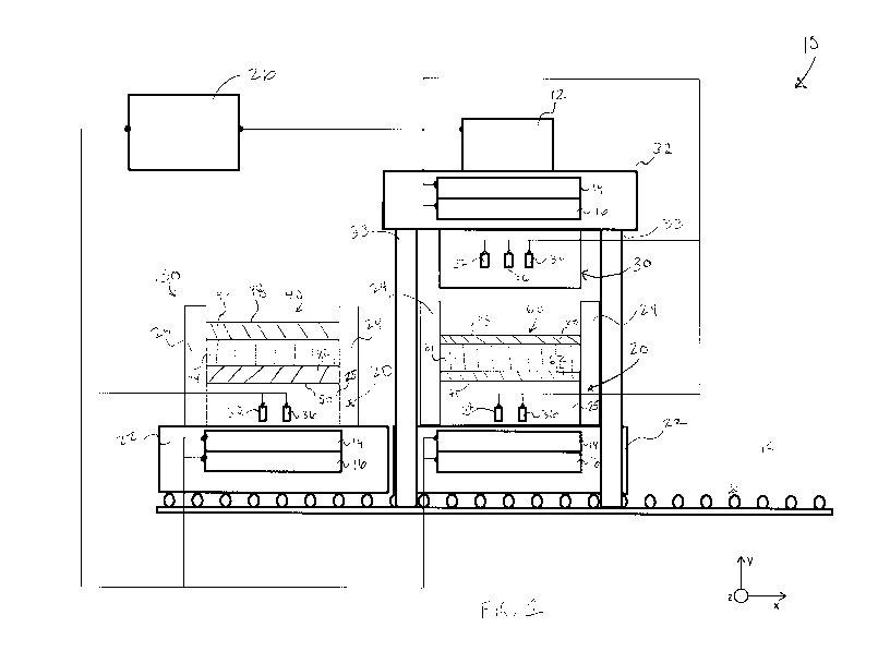
[0013] FIG. 1 schematically depicts a system for forming aggregate
materials
according to one or more embodiments shown and described herein;
[0014] FIG. 2A schematically depicts a process for forming aggregate
materials
according to one or more embodiments shown and described herein;
[0015] FIG. 2B schematically depicts a process for forming aggregate
materials
according to one or more embodiments shown and described herein;
[0016] FIG. 3 depicts a flow chart of exemplary control logic for forming
aggregate
materials according to one or more embodiments shown and described herein;
[0017] FIG. 4 depicts a flow chart of exemplary control logic for forming
aggregate
materials according to one or more embodiments shown and described herein; and
[0018] FIG. 5 depicts a flow chart of exemplary control logic for forming
aggregate
materials according to one or more embodiments shown and described herein.
DETAILED DESCRIPTION
[0019] As used herein with the various illustrated embodiments described
below, the
following terms include, but are not limited to, the following meanings.
[0020] The term "sensor" means a device that detects a physical quantity
and
converts it into a signal that is correlated to the detected value of the
physical quantity.
CA 02849108 2014-03-18
WO 2013/049132 PCT/US2012/057234
-7-
[0021] The term "signal" means a waveform (e.g., electrical, optical,
magnetic, or
electromagnetic waveforms) capable of traveling through a medium such as DC,
AC,
sinusoidal-wave, triangular-wave, square-wave, and the like.
[0022] The phrase "communicatively coupled" means that components are
capable
of exchanging data signals with one another such as, for example, electrical
signals via
conductive medium, electromagnetic signals via air, optical signals via
optical waveguides,
and the like.
[0023] FIG. 1 generally depicts one embodiment of a system for forming
aggregate
materials. The system generally comprises an upper mold, a lower open-topped
mold, an
actuation assembly for generating relative motion between the molds and a
heating system
for heating the molds. Various embodiments of the system for forming aggregate
materials
and the operation of the system will be described in more detail herein.
[0024] Referring now to FIG. 1, the system 10 may comprise a lower open-
topped
mold 20 for imparting a shape upon a raw material. The lower open-topped mold
20 can
comprise one or more sidewalls 24 that that are configured to surround raw
material that is
shaped by the mold and a base 25 that cooperates with the one or more
sidewalls 24 to form a
mold shape. The lower open-topped mold 20 may be coupled to a lower support
structure 22
that is capable of supporting the lower open-topped mold 20 and withstanding
repeated
actuation, as is described in greater detail herein.
[0025] The system 10 may further comprise an upper mold 30 that
cooperates with
the lower open-topped mold 20 to impart a shape upon a raw material. For
example, the
upper mold 30 and the lower open-topped mold 20 may cooperate and interlock
such that a
raw material is substantially enclosed throughout a molding process. The upper
mold 30 may
be coupled to an upper support structure 32 that is capable of durably
supporting the upper
mold 30 for multiple molding cycles, i.e., the molds may be used in repeated
cycles to
produce a high volume of molded articles. The lower open-topped mold 20 and
the upper
mold 30 may be formed from any material suitable to withstand repeated
thermodynamic
cycling while maintaining a substantially controlled shape such as, for
example, a metallic
(e.g., aluminum) or ceramic. Furthermore, it is noted that the lower support
structure 22 and
the upper support structure 32 may be formed from similar materials as the
lower open-
CA 02849108 2014-03-18
WO 2013/049132 PCT/US2012/057234
-8-
topped mold 20 and the upper mold 30 or any other material having
substantially similar or
lower thermal conductivity.
[0026] Referring still to FIG. 1, the system 10 may further include an
actuation
assembly 12 for generating relative motion between the lower open-topped mold
20 and the
upper mold 30. Specifically, the actuation assembly 12 can be utilized to
control the position
of the lower open-topped mold 20 and the upper mold 30 to allow raw material
to be loaded
into the lower open-topped mold 20. Moreover, the actuation assembly 12 may
provide
pressure to the lower open-topped mold 20 and the upper mold 30 while the raw
material is
being shaped by the lower open-topped mold 20 and the upper mold 30. The
actuation
assembly 12 may include any number of actuators capable of transferring a
controlled
amount of force upon the lower open-topped mold 20, the upper mold 30, or
both. For
example, such actuators may be pneumatic, electrical, hydraulic, or any other
device capable
of transforming an input signal into motion. Moreover, each actuator may be
linear or rotary.
In some embodiments, the actuation assembly 12 may comprise a linear actuator
disposed at
each corner of a square shaped support structure coupled to upper mold 30.
[0027] The system 10 may comprise a heating system for providing thermal
energy
to an endothermic molding process. Specifically, the heating system may
include a plurality
of heating devices 14 in thermal communication with the lower open-topped mold
20 and the
upper mold 30 that cause the raw material to achieve a higher temperature. The
heating
devices may be electrical resistive heating elements, inductive heating
elements, or any other
device capable of transferring a substantially even amount of thermal energy
across a surface
of the raw material and/or a surface of a mold. The thermal energy can be
produced by the
heating devices 14 and then transferred to the raw material by conduction,
convection or
radiation. Accordingly, it is noted that while, the heating devices 14 are
depicted FIG. 1 as
being located within the upper support structure 32 and the lower support
structure 22, the
heating devices 14 may be located external to the upper support structure 32,
the lower
support structure 22, the upper mold 30 and/or the lower open-topped mold 20.
The heating
devices 14 may alternatively or additionally be located within the upper mold
30 and/or the
lower open-topped mold 20.
[0028] The system 10 may further comprise a cooling system for reducing
the
temperature of the raw material. For example, the cooling system may include a
plurality of
CA 02849108 2014-03-18
WO 2013/049132 PCT/US2012/057234
-9-
cooling devices 16 in thermal communication with the lower open-topped mold 20
and the
upper mold 30. The cooling devices 16 may be flow paths through which a
cooling fluid is
directed to remove heat from the raw material, or any other device capable of
removing
thermal energy from the raw material by conduction, convection or radiation.
Furthermore, it
is noted that while, the cooling devices 16 are depicted FIG. 1 as being
located within the
upper support structure 32 and the lower support structure 22, the cooling
devices 16 may be
located external to the upper support structure 32, the lower support
structure 22, the upper
mold 30 and/or the lower open-topped mold 20. The cooling devices 16 may
alternatively or
additionally be located within the upper mold 30 and/or the lower open-topped
mold 20.
[0029] The system 10 may further comprise a pressure sensor 34 for
measuring the
back pressure provided by the raw material during a molding process.
Accordingly, the
pressure sensor 34 may be any sensor capable of detecting the resistive force
of the raw
material during processing such as, but not limited to, a load cell, a force
transducer, an
absolute pressure sensor, a gauge pressure sensor, or a differential pressure
sensor. It is noted
that, while the pressure sensor 34 is depicted as being located within the
upper mold 30, the
pressure sensor 34 may be located anywhere in the system 10 such that the
pressure sensor is
operable to detect the back pressure of the raw material such as, for example,
within the
lower open-topped mold 20, the upper mold 30, the upper support structure 32,
the lower
support structure 22, the actuation assembly 12, or combinations thereof.
[0030] The system 10 may also comprise a position sensor 36 for detecting
the
position of the lower open-topped mold 20 and/or the upper mold 30.
Specifically, the
absolute and/or relative position of each of the lower open-topped mold 20 and
the upper
mold 30 may be detected along a single axis or multiple axes. Accordingly, the
position
sensor 36 may be any sensor capable of detecting linear and/or angular
position such as an
encoder, an optical sensor, an electrical sensor, and the like. It is noted
that, while the
position sensor 36 is depicted as being located within the upper mold 30 and
the lower open-
topped mold 20, the position sensor 36 may be located anywhere in the system
10 such that
the position sensor 36 is operable to detect the lower open-topped mold 20 and
the upper
mold 30 such as, for example, within the actuation assembly 12, the lower open-
topped mold
20, the upper mold 30, the upper support structure 32, the lower support
structure 22, the
actuation assembly 12, or combinations thereof.
CA 02849108 2014-03-18
WO 2013/049132 PCT/US2012/057234
-10-
[0031] The system 10 may comprise a temperature sensor 38 for detecting
the
temperature of the raw material. The temperature sensor 38 may be any sensor
capable of
detecting the temperature of the raw material directly or indirectly by
measuring the
temperature of the other components of the system 10. The temperature sensor
38 may
include any device capable of detecting temperature such as, but not limited
to, a
thermometer, a thermocouple, a thermostat, infrared detector, and the like. It
is noted that,
while the temperature sensor 38 is depicted as being located within the upper
mold 30 and the
lower open-topped mold 20, the temperature sensor 38 may be located anywhere
in the
system 10 such that the temperature sensor 38 is operable to detect the
temperature of and/or
in thermal communication with the raw material such as, for example, within
the lower open-
topped mold 20, the upper mold 30, the upper support structure 32, the lower
support
structure 22, the actuation assembly 12, or combinations thereof.
[0032] The system 10 comprises a controller 26 for executing machine
readable
instructions to control various aspects of the molding process. The controller
26 may be a
processor, an integrated circuit, a microchip, a computer, programmable logic
controller or
any other computing device capable of executing machine readable instructions.
The
controller 26 may be communicatively coupled to a memory such as RAM, ROM,
EPROM,
EEPROM, a flash memory, a hard drive, or any device capable of storing machine
readable
instructions. Accordingly, the memory may store molding control logic and/or
process
recipes.
[0033] Thus, embodiments of the present disclosure may comprise control
logic or
an algorithm written in any programming language of any generation (e.g., 1GL,
2GL, 3GL,
4GL, or 5GL) such as, e.g., machine language that may be directly executed by
the controller,
or assembly language, object-oriented programming (00P), scripting languages,
microcode,
etc., that may be compiled or assembled into machine readable instructions and
stored on a
machine readable medium. Alternatively, the logic or algorithm may be written
in a
hardware description language (HDL), such as implemented via either a field-
programmable
gate array (FPGA) configuration or an application-specific integrated circuit
(ASIC), and
their equivalents.
[0034] Referring still to FIG. 1, one embodiment of the system 10 for
forming
aggregate materials is depicted. The system 10 may comprise an upper support
structure 32
CA 02849108 2014-03-18
WO 2013/049132 PCT/US2012/057234
-11-
that is configured to move up and down a vertical axis (depicted in FIG.1 as
the y-axis). For
example, the upper support structure 32 may be slidingly engaged with a
plurality of vertical
risers 33. The actuation assembly 12 can be coupled to the upper support
structure 32 to
transport the upper support structure 32 vertically. The system 10 may further
comprise a
lower support structure 22 that can be positioned below the upper support
structure 32.
Accordingly, when the upper support structure 32 moves along the vertical
axis, the distance
between the upper support structure 32 and the lower support structure 22 can
be adjusted by
the actuation assembly 12.
[0035] As is noted above, an upper mold 30 may be coupled to the upper
support
structure 32 and a lower open-topped mold 20 may be coupled to the lower
support structure
22. Accordingly, the actuation assembly 12 can generate relative inward motion
between the
lower open-topped mold 20 and the upper mold 30 and relative outward motion
between the
lower open-topped mold 20 and the upper mold 30. Specifically, in the
embodiment depicted
in FIG. 1, the actuation assembly 12 may move the upper support structure 32
in the negative
y-direction to cause relative inward motion between the lower open-topped mold
20 and the
upper mold 30. The actuation assembly 12 may move the upper support structure
32 in the
positive y-direction to cause relative inward motion between the lower open-
topped mold 20
and the upper mold 30.
[0036] Thusly, the actuation assembly 12 may move the upper mold 30
throughout a
range of positions that may include and be bounded by an open position and a
clamped
position. In the open position, the upper mold 30 can be moved away from the
lower open-
topped mold 20 such that the upper mold 30 is separated from the from the
lower open-
topped mold 20 along the y-axis. In the clamped position, the actuation
assembly 12 forces
the upper mold 30 into contact with the lower open-topped mold 20 such that
further motion
of the upper mold 30 along the negative y-direction is limited by the lower
open-topped mold
20. It is noted that, while the actuation assembly 12 is depicted in FIG. 1 as
being coupled to
the upper support structure 32, the actuation assembly 12 may alternatively or
additionally be
coupled to any component of the system 10 such as the lower support structure
22, or any
other component sufficient to allow the upper mold 30 and the lower open-
topped mold 20 to
move throughout an open position, a clamped position, and/or any position
there between.
CA 02849108 2014-03-18
WO 2013/049132 PCT/US2012/057234
-12-
[0037] In some embodiments, the system 10 may comprise a conveyance
system 18
for moving the lower support structure 22 laterally (depicted in FIG. 1 as
along the x-axis).
Accordingly, the lower open-topped mold 20 can be moved in and out of
alignment with the
upper mold 30. Furthermore, it is noted that, while the conveyance system 18
is depicted in
FIG. 1 as a roller conveyer, the conveyance system 18 may be any motive system
capable of
moving the lower support structure 22. For example, the conveyance system 18
may include
belts, enclosed tracks, I-Beams, towlines, and/or manually actuated rollers
and/or wheels.
Moreover, it is noted that, while the conveyance system 18 is depicted in FIG.
1 as being
linear and accommodating two lower support structures 22, the conveyance
system 18 may
be any shape and may accommodate any number of lower support structures 22 for
batch
processing of aggregate materials.
[0038] The controller 26 can be communicatively coupled to various
components of
the system 10 and execute machine readable control logic to shape raw material
into an
aggregate material. In some embodiments, the controller 26 can be
communicatively coupled
to the actuation assembly 12, heating devices 14, cooling devices 16, pressure
sensors 34,
position sensors 36 and temperature sensors 38. Accordingly, the controller 26
follow
control logic to direct the system 10 in forming a heat moldable material 40
into an aggregate
material 60 according to a process recipe.
[0039] The heat moldable material 40 may be a thermoplastic such as, for
example,
polyolefins (e.g. polyethylenes, styrenics such as polystyrene, polyesters
such as PET),
thermosets (e.g. phenolics) and rubbers. The heat moldable material 40
generally comprises
a temperature and/or a chemically activated foaming agent (blowing agent) such
as, for
example, exothermics, endothermics, and/or physical systems. Accordingly, the
foaming
agent may have an activation temperature at which the foaming agent forms a
foam which
causes expansion of the heat moldable material 40. Suitable exothermics
include, but are not
limited to, azodicarbonamide (e.g., Porofor available from Lanxess or Celogen
available
from Lion Copolymer), or sodium bicarbonate. Suitable endothermics include,
but are not
limited to, hydroxypropane tricarboxylic acid (e.g. Hydrocerol available from
Clariant).
Physical systems can include for example nitrogen, pentane, or other gases,
which can be
preimpregnated in polystyrene or expanded polypropylene and released as a gas.
CA 02849108 2014-03-18
WO 2013/049132 PCT/US2012/057234
-13-
Alternatively, nitrogen can be utilized in a system such as a "Zotefoam"
nitrogen saturation
process.
[0040] The heat moldable material 40 may comprise one or more distinct
layers. For
example, the heat moldable material 40 may comprise a lower layer 42, an upper
layer 46 and
a core layer 44 disposed between the lower layer 42 and the upper layer 46.
The lower layer
42 may comprise relatively fine grain material that forms a lower surface 50.
Similarly, the
upper layer 46 may comprise relatively fine grain material that forms an upper
surface 48.
The fine grain material can be a thermoplastic powder (e.g. polyethylene)
where the average
grain size is about 1001..tm to about 3,000 [im in one embodiment, and in
another
embodiment, for example, from about 500 [im to about 100 pm. Accordingly, heat
moldable
material 40 may be processed as described herein to form an aggregate material
60 having a
lower skin layer 62 formed from the lower layer 42 and an upper skin layer 66
formed from
the upper layer 46. It is believed, without being bound to theory, that the
relatively fine grain
material conforms more completely to the upper mold 30 and the lower open-
topped mold
relatively closely. Accordingly, the upper surface 68 and lower surface 70 may
be made
relatively smooth with smooth molds or may be made to more closely replicate
the desired
mold shape (e.g., to simulate natural stone, brick, timber, or any other
building material).
[0041] The core layer 44 of the heat moldable material 40 may comprise a
foaming
agent. In some embodiments, the core layer may be formed from a relatively
coarse grain
material compared to the lower layer 42 and the upper layer 46. The coarse
grain material
can be a thermoplastic powder (e.g. polyethylene) where the average grain of
up to about 10
mm. Moreover, the core layer may further comprise filler material such as, for
example,
recycled material (e.g., paper, cardboard, rubber, plastics, metal, fibers and
minerals), glass
fiber, carbon fiber, reinforcement steel mesh, organic fiber (e.g., bamboo or
banana), or
material intended to add specific properties (e.g., fire-retardant material or
anti-ballistic
material). Accordingly, the core layer 44 may comprise thermoplastics, foaming
agents, and
filler material in proportions suitable to allow the core layer 44 to fuse
with the lower layer
42 and the upper layer 46 to form an aggregate material 60.
[0042] Referring collectively to FIGS. 2A and 2B, one embodiment of a
method for
forming an aggregate material is schematically depicted. At step 110, the
lower layer 42 can
be dispensed into the lower open-topped mold 20, such that the lower surface
50 is in contact
CA 02849108 2014-03-18
WO 2013/049132 PCT/US2012/057234
-14-
with the lower open-topped mold 20. At step 120, the core layer 44 can be
dispensed into the
lower open-topped mold 20 over the lower layer 42. As is noted above, the core
layer 44
may include foaming agents and filler material. The foaming agent and/or the
filler material
may be pre-mixed with the core layer 44 and dispensed simultaneously as a
constituent of the
core layer 44. Additionally or alternatively, each of the core layer 44
constituents can be
dispensed as individual layers.
[0043] At step 130, the upper layer 46 can be dispensed into the lower
open-topped
mold 20 over the core layer 44. Each of the lower layer 42, the core layer 44,
and the upper
layer 46 can be dispensed into the lower open-topped mold by a powder
dispensing unit (not
depicted). The powder dispensing unit can be any device capable of loading
measured
amounts of fine grain material and/or coarse grain material. In some
embodiments, the
sidewalls 24 and the base 25 of the lower open-topped mold 20 can move
vertically with
respect to one another to assist with the loading of the heat moldable
material 40. For
example, the sidewalls 24 may be lowered to a predetermined location with
respect to the
base 25 when one or more layers of the heat moldable material 40 are
dispensed. A roller or
a plane tool may be indexed by the sidewalls 24 and remove excess material
that extends
above the sidewall 24 to ensure the desired amount of material is loaded in
the lower open-
topped mold 20.
[0044] Referring back to FIG. 1, it is noted that, the heat moldable
material 40 may
be dispensed into the lower open-topped mold 20, when the lower open-topped
mold 20 is
not aligned with the upper mold 30. Accordingly, heat moldable material 40 may
be loaded
into one or more lower open-topped molds 20 by one or more powder dispensing
units, while
another lower open-topped mold 20 is aligned with the upper mold 30.
[0045] Referring collectively to FIGS. 1 and 2A, at step 140 a lower open-
topped
mold 20 housing the heat moldable material 40 may be aligned with the upper
mold 30. For
example, position sensors 36 may detect the orientation of the lower open-
topped mold 20
and the upper mold 30 along the x-axis and the z-axis. When the lower open-
topped mold 20
and the upper mold 30 are detected as being aligned by the position sensors
36, the controller
26 can cause the actuation assembly 12 to generate relative inward motion of
the lower open-
topped mold 20 and the upper mold 30. The upper mold 30 can be lowered into
contact with
the upper surface 48 of the heat moldable material 40, and the lower open-
topped mold 20
CA 02849108 2014-03-18
WO 2013/049132 PCT/US2012/057234
-15-
can contact the lower surface 50 of the heat moldable material 40.
Accordingly, the heat
moldable material 40 can be enclosed by the lower open-topped mold 20 and the
upper mold
30.
[0046] Referring collectively to FIGS. 1 and 2B, the embodiments
described herein
may optionally include step 150 and step 160. At step 150, the lower open-
topped mold 20
and the upper mold 30 can be heated with the heating system to a pre-heat
temperature. The
pre-heat temperature may be any temperature wherein the lower layer 42 and the
upper layer
46 fuses into a viscous material and the foaming agent remains below its
activation
temperature. For example, in one embodiment, the pre-heat temperature can be
up to about
350 C, in another embodiment, such as for example, from about 130 C to about
310 C, in
still another embodiment, from about 190 C to about 220 C, and in yet
another
embodiment, about 170 C. At step 160, the lower layer 42 can be fused into a
viscous lower
layer 58 and the upper layer 46 can be fused into a viscous upper layer 56.
The controller 26
can cause the actuation assembly 12 to generate relative inward motion between
the lower
open-topped mold 20 and the upper mold 30.
[0047] Referring collectively to FIGS. 1 and 3, the viscous lower layer
58 and the
viscous upper layer 56 can be formed according to a flow process 200. At step
202, the lower
open-topped mold 20 and the upper mold 30 can be heated to the pre-heat
temperature. At
step 204, the controller 26 can receive a position measurement from the
position sensor 36.
The controller 26 can determine if the position indicates that the combined
thickness of the
fusing material has reached a desired thickness. The desired thickness can be
set in
accordance with the process recipe and can be about 10 mm for a process recipe
for making a
building board. If the measured thickness is less than or equal to the desired
thickness
(indicated in FIG. 3 with a "+"), the controller 26 can cause the flow process
to proceed to
step 212. At step 212, the flow process ends.
[0048] If the measured thickness is greater than the desired thickness
(indicated in
FIG. 3 with a "-"), the controller 26 can cause the flow process 200 to
proceed to step 206.
At step 206, the controller 26 can receive a force measurement from the
pressure sensor 34.
The controller 26 can determine if the force measurement exceeds a flow force
limit. The
flow force limit can be set in accordance with the process recipe and can be
from about 0.2
kN to about 1 kN in one embodiment, and in another embodiment, for example,
about 0.5 kN
CA 02849108 2014-03-18
WO 2013/049132 PCT/US2012/057234
-16-
such as for a process recipe for making a building board. If the force
measurement exceeds
the flow force limit (indicated in FIG. 3 with a "+"), the controller 26 can
cause the flow
process to proceed to step 212. If the force measurement does not exceed the
flow force limit
(indicated in FIG. 3 with a "-"), the controller 26 can cause the flow process
to proceed to
step 208.
[0049] At step 208, the controller 26 can receive a force measurement
from the
pressure sensor 34. The controller 26 can determine if the force measurement
is less than the
flow force limit. If the force measurement is less than the flow force limit
(indicated in FIG.
3 with a "+"), the controller 26 can cause the flow process to proceed to step
210. At step
210, the controller 26 can cause the actuation assembly 12 to incrementally
move to generate
relative inward motion between the lower open-topped mold 20 and the upper
mold 30. The
size of the increment may be set such that in operation the molds move at a
desired rate.
The desired rate can be set in accordance with the process recipe. The desired
rate can be less
than about 2 mm/minute in one embodiment, and in another embodiment, for
example, about
1.6 mm/min (about 0.026 mm/sec) such as for a process recipe for making a
building board.
If the force measurement is not less than the flow force limit (indicated in
FIG. 3 with a "-"),
the controller 26 can cause the flow process to proceed back to step 204.
[0050] Referring again to FIG. 2B, the upper mold 30 and the lower open-
topped
mold 20 can be heated to a foaming temperature at step 170. The foaming
temperature can
be any temperature suitable to cause the foaming agent to reach its activation
temperature.
For example, the foaming agent can be heated to its activation temperature
causing the core
layer 44 to transform into a foam 54. In some embodiments, filler material can
be inserted
into the foam 54 through the sidewalls 24 of the lower open-topped mold 20. As
the foam 54
expands, the foam exerts a force (i.e., back pressure) upon the upper mold 30
and the lower
open-topped mold 20. The upper mold 30 and the lower open-topped mold 20 can
be moved
outward with respect to one another based upon the back pressure. Accordingly,
the lower
open-topped mold 20 and the upper mold 30 can maintain close contact with the
heat
moldable material 40.
[0051] Referring collectively to FIGS. 1 and 4, the foam 54 can be formed
according
to a foam process 300. At step 302, the lower open-topped mold 20 and the
upper mold 30
can be heated to the foaming temperature. The foaming temperature may be any
temperature
CA 02849108 2014-03-18
WO 2013/049132 PCT/US2012/057234
-17-
wherein the heat moldable material 40 fuses and the foaming agent reaches its
activation
temperature. For example, in one embodiment the foaming temperature can be up
to about
350 C, in another embodiment, such as for example, from about 140 C to about
280 C, in
still other embodiment from about 190 C to about 220 C, and about 210 C in
yet another
embodiment.
[0052] At step 304, the controller 26 can receive a foam force
measurement from the
pressure sensor 34. The controller 26 can determine if the foam force
measurement exceeds a
foam force limit plus a foam tolerance. The foam force limit and the foam
tolerance can be
set in accordance with the process recipe. The foam force limit can be in one
embodiment
from about 1 kN to about 20 kN, and in another embodiment, for example, about
0.5 kN such
as for a process recipe for making a building board. The foam tolerance can be
in one
embodiment from about 0 kN to about 5 kN, and in another embodiment, for
example, about
0.2 kN such as for a process recipe for making a building board. If the foam
force
measurement exceeds the foam force limit plus the foam tolerance (indicated in
FIG. 5 with a
"+"), the controller 26 can cause the foam process 300 to proceed to step 306.
At step 306,
the controller 26 can cause the actuation assembly 12 to incrementally
generate relative
outward motion between the lower open-topped mold 20 and the upper mold 30.
The size of
the increment may be set such that in operation the molds move at an expansion
rate
sufficient to respond to the rate of expansion of the foaming agent at the
foaming
temperature. Following step 306, the controller 26 can cause the foam process
300 to
proceed to step 304.
[0053] If the foam force measurement does not exceed the foam force limit
plus the
foam tolerance (indicated in FIG. 4 with a "-"), the controller 26 can cause
the flow process
to proceed to step 308. At step 308, the controller 26 can receive a foam
force measurement
from the pressure sensor 34. The controller 26 can determine if the foam force
measurement
is less than a foam force limit minus the foam tolerance. If the foam force
measurement is
less than the foam force limit minus the foam tolerance (indicated in FIG. 5
with a "+"), the
controller 26 can cause the foam process 300 to proceed to step 310. At step
310, the
controller 26 can cause the actuation assembly 12 to incrementally generate
relative inward
(i.e., bringing together) motion between the lower open-topped mold 20 and the
upper mold
30. The size of the increment may be set such that in operation the molds move
at a
CA 02849108 2014-03-18
WO 2013/049132 PCT/US2012/057234
-18-
contraction rate sufficient to respond to the rate of contraction of the
foaming agent during
the foaming process. Following step 310, the controller 26 can cause the foam
process 300 to
proceed to step 304.
[0054] If the foam force measurement is greater than the foam force limit
minus the
foam tolerance (indicated in FIG. 4 with a "-"), the controller 26 can cause
the foam process
300 to proceed to step 312. At step 312, the controller 26 can receive a
position measurement
from the position sensor 36. The controller 26 can determine if the position
indicates that the
heat moldable material 40 is less than a nominal thickness plus a foam offset.
The nominal
thickness and the foam offset can be set in accordance with the process
recipe. For example,
the nominal thickness can be in one embodiment from about 5 mm to about 50 mm,
in
another embodiment about 8 mm to about 20 mm, and in still another embodiment,
for
example, about 8 mm such as for a process recipe for making a building board.
The foam
offset can be in one embodiment from about 0.2 mm to about 1.5 mm, and in
another
embodiment, for example, about 1 mm such as for a process recipe for making a
building
board. If the measured thickness is less the heat moldable material 40 is less
than a nominal
thickness plus a foam offset (indicated in FIG. 5 with a "+"), the controller
26 can cause the
foam process 300 to proceed back to step 304.
[0055] If the measured thickness of the heat moldable material 40 is
greater than or
equal to the nominal thickness plus the foam offset (indicated in FIG. 4 with
a "-"), the
controller 26 can cause the foam process 300 proceed to step 314. At step 314,
the foam
process 300 ends.
[0056] Referring again to FIG. 2B, the upper mold 30 and the lower open-
topped
mold 20 can be cooled to a cooling temperature at step 180. The cooling
temperature can be
any temperature suitable to solidify the aggregate material 60 into a stable
product for
handling or further processing. For example, the cooling temperature can be in
one
embodiment from about 30 C to about 80 C, and in another embodiment, for
example,
about 50 C such as for a process recipe for making a building board.
[0057] As the foam 54 is cooled, the foam 54 may contract to reduce the
back
pressure upon the upper mold 30 and the lower open-topped mold 20. The upper
mold 30
and the lower open-topped mold 20 can be moved inward with respect to one
another based
CA 02849108 2014-03-18
WO 2013/049132 PCT/US2012/057234
-19-
upon the back pressure. Accordingly, the lower open-topped mold 20 and the
upper mold 30
can maintain close contact with the heat moldable material 40 during cooling,
for example, as
discussed hereafter. It is to be appreciated that by close contact it is meant
that the upper
mold 30 maintains contact substantially over the entire surface area of the
upper surface 48 of
the building material during at least the cooling process such that bowing
i.e.,
distortion/movement of portions of the cooling building material in or out of
the general
contours defined by the facing surfaces of the upper and lower molds, is
substantially
prevented.
[0058] Referring collectively to FIGS. 1 and 5, the heat moldable
material 40 can be
cooled according to a cooling process 400. At step 402, cooling devices 16 may
be activated
by the controller 26 to cool the lower open-topped mold 20 and the upper mold
30. At step
404, the controller 26 can receive a cooling force measurement from the
pressure sensor 34.
The controller 26 can determine if the cooling force measurement is less than
the foam force
limit. If the cooling force measurement is less than the foam force limit
(indicated in FIG. 5
with a "+"), the controller 26 can cause the cooling process 400 to proceed to
step 406. If the
cooling force measurement is greater than or equal to the foam force limit
(indicated in FIG.
with a "-"), the controller 26 can cause the cooling process 400 to proceed to
step 410.
[0059] At step 406, the controller 26 can receive a position measurement
from the
position sensor 36. The controller 26 can determine if the position indicates
that the heat
moldable material 40 is greater than a nominal thickness. If the measured
thickness is greater
than the nominal thickness (indicated in FIG. 5 with a "+"), the controller 26
can cause the
cooling process 400 to proceed to step 408. If the measured thickness is less
than or equal to
the nominal thickness (indicated in FIG. 5 with a "-"), the controller 26 can
cause the cooling
process 400 to proceed back to step 404.
[0060] At step 408, the controller 26 can cause the actuation assembly 12
to
incrementally generate relative inward motion between the lower open-topped
mold 20 and
the upper mold 30. The size of the increment may be set such that, in
operation, the molds
move at a rate sufficient to respond to the rate of contraction of the foaming
agent during the
cooling process. Following step 408, the controller 26 can cause the cooling
process 400 to
proceed back to step 404.
CA 02849108 2014-03-18
WO 2013/049132 PCT/US2012/057234
-20-
[0061] At step 410, the controller 26 can receive a temperature
measurement from
the temperature sensor 38. The controller 26 can determine if the temperature
measurement
indicates that the heat moldable material 40 is greater than the cooling
temperature. If the
temperature measurement is greater than the cooling temperature (indicated in
FIG. 5 with a
"+"), the controller 26 can cause the cooling process 400 to proceed back to
step 404. If the
temperature measurement is less than or equal to the cooling temperature
(indicated in FIG. 5
with a "-"), the controller 26 can cause the cooling process 400 to proceed to
step 412. At
step 412, the cooling devices 16 may be deactivated by the controller 26. The
cooling
process 400 can then proceed to step 414, where the cooling process 400
terminates.
[0062] It is to be appreciated that the above described process may be
used in one
embodiment according to a process recipe for making a building board, that is
also described
above, to form such building boards having a total thickness of about 18 mm
(about 3/4 inch),
skin layers from about 1 to about 1 1/2 mm thick and a core layer about 15 mm
thick. Such
building boards can be made up to about 10 cm total thickness with skin layers
from about
0.5 mm to about 7 mm thick following the described process recipe. It is noted
that various
attributes of the process recipe such as, but not limited to, temperatures,
forces, thicknesses,
inward increments, and outward increments can be adjusted to achieve other
desired output
aggregate materials, such as for example, simulate natural stone, simulated
natural brick,
simulated stone veneer, simulated brick veneer, tile, simulated natural
timber, siding,
engineered lumber, and any other such desired manufactured/composite/layered
building
material. Moreover, it is noted that the process recipe may depend upon the
attributes (e.g.,
size, shape, amount, proportion, chemistry) of the fine grain material, the
coarse grain
material, the foaming agent, and/or the filler material.
[0063] Referring again to FIG. 1, a heat moldable material 40 may be
formed, as
described herein, into an aggregate material 60 comprising a lower skin layer
62, an upper
skin layer 66, and a core layer 64 integrally formed there between. The lower
skin layer 62
can form a lower surface 70 and the upper skin layer 66 can form an upper
surface 68. Each
of the lower surface 70 and the upper surface 68 can be formed into a desired
shape
according to the molding systems described herein. The core layer 64 may have
cellular
voids formed therein, which may yield a relatively light structure, e.g., as
compared to a
CA 02849108 2014-03-18
WO 2013/049132 PCT/US2012/057234
-21-
corresponding natural building material. Moreover, the core layer may be
impregnated with
filler material as described herein.
[0064] The aggregate material 60 can be removed from the system 10 via
ejector
pins (not depicted) integral with the lower open-topped mold 20 and/or the
upper mold 30.
Alternatively or additionally, the lower open-topped mold 20 and/or the upper
mold 30 can
be heated by the heating system to a temperature that facilitates removal. In
some
embodiments, the base 25 and the sidewalls 24 of the lower open-topped mold
may move
relative to one another to eject the aggregate material 60. For example, the
base 25 may slide
vertically. In embodiments where the sidewalls 24 are shaped to impart
features upon the
aggregate material 60 (e.g., tongues and/or grooves), the sidewalls 24 may be
removed and or
rotate about the base 25. It is noted that the aggregate materials 60 can be
formed with a
batch processing layout where powder dosing, mold interlocking, heating,
pressing, cooling,
and/or removal are each performed at separate locations along a production
line and/or by
different machines.
[0065] It is noted that the terms "substantially" and "about" may be
utilized herein to
represent the inherent degree of uncertainty that may be attributed to any
quantitative
comparison, value, measurement, or other representation. These terms are also
utilized
herein to represent the degree by which a quantitative representation may vary
from a stated
reference without resulting in a change in the basic function of the subject
matter at issue.
[0066] Furthermore, it is noted that the embodiments described herein
have been
provided with an xyz coordinate system for clarity. Accordingly, the xyz
coordinate system
can be transformed into any other coordinate system without departing from the
scope of the
description. Moreover, directional terms such as vertical, lateral, inward,
outward, and the
like have been described with respect to the provided coordinate system and
are not intended
to be limiting.
CA 02849108 2014-03-18
WO 2013/049132
PCT/US2012/057234
-22-
[0067] While
particular embodiments have been illustrated and described herein, it
should be understood that various other changes and modifications may be made
without
departing from the spirit and scope of the claimed subject matter. Moreover,
although
various aspects of the claimed subject matter have been described herein, such
aspects need
not be utilized in combination. It is therefore intended that the appended
claims cover all
such changes and modifications that are within the scope of the claimed
subject matter.