Note: Descriptions are shown in the official language in which they were submitted.
CA 02849412 2014-03-20
1
AN ATTACHMENT COLLAR FOR ELONGATE ELEMENTS
The present invention relates to an attachment
collar for elongate elements, the collar being of the
type comprising a belt portion suitable for being
fastened to a support, the belt portion being open and
defining an inside space suitable for receiving the
elongate element, the collar further comprising means for
closing the belt portion so as to retain the elongate
elements in the inside space.
The collar of the present invention is particularly
adapted to attaching cables or pipes. It may be used in
all industrial sectors, in particular in aviation for
guiding the passage of cables along cabin walls.
An already-known attachment collar 100, as shown in
Figure 1, is for attaching bundles of cables 300 to a
support 200. The collar 100 comprises a belt portion 130
made of thermoplastic material, forming an open inside
space 138 for receiving the cables 300. In order to
prevent the cables 300 from escaping from the inside
space 138, a cable tie 150 is inserted in slots 160
formed at each of the free ends 130a, 130b of the belt
portion 130. A fastener tab 140 that is secured to the
belt portion 130 is adapted to co-operate with a screw
170 for fastening the attachment collar 100 to the
support 200.
That type of collar presents numerous drawbacks.
Such collars are awkward to use because the operator
needs to insert the cable tie 150 into the slots 160 that
are small in size and that are formed at the free ends
130a, 130b of the belt portion 130. Thereafter, in
particular during maintenance operations, the operator
usually needs to use pliers and carefully manipulate the
closure zone of the cable tie in order to reopen the belt
portion 130 and extract the cables 300 therefrom. There
is a major risk that in so doing at least one cable will
be damaged or cut through.
CA 02849412 2014-03-20
,
2
Another example of an attachment collar of the
above-specified type is disclosed in document
US 3 429 985. That collar has the drawback of the
elements not being retained therein in reliable manner,
and also the drawback that closing the collar depends on
there being elements present in the inside space of the
belt portion and on the diameter of such elements.
One of the objects of the present invention is to
provide an attachment collar for elongate elements that
makes it possible to remedy that above-mentioned
drawbacks of the prior art.
In particular, the present invention seeks to
provide an attachment collar that can be closed and
reopened easily and safely in such a manner that the
elongate elements retained by the collar do not run the
risk of being damaged, in particular during maintenance
operations.
This object is achieved by an attachment collar of
the above-specified type, in which the means for closing
the belt portion comprise firstly an array of gripping
elements made of plastics material injected integrally
with the belt portion and situated on its outside face,
and secondly a tape secured to the belt portion via one
of its ends, the inside face of the tape presenting
retention means suitable for co-operating with the
gripping elements of the belt portion in order to secure
the tape and the belt portion together, the belt portion
presenting stiffness that is greater than the stiffness
of the tape.
The attachment collar of the invention is closed by
a self-gripping system that enables the collar to be
opened and closed easily and repeatedly merely by
pressing the tape down onto the belt portion.
The collar can be opened manually without requiring
the use of sharp tools, and there is no risk of damaging
the elongate elements received in the inside space of the
belt portion.
CA 02849412 2014-03-20
3
Furthermore, closure is achieved very easily. In
order to release the elements arranged inside the inside
space of the belt portion, it is necessary to
deliberately peel off the tape such that unwanted opening
is prevented.
Finally, the tape and the belt portion are fastened
together by co-operation between the gripping elements
and the retention means, independently of whether any
elements are or are not present in the inside space of
the belt portion and independently of the diameter(s) of
such elements.
The gripping elements may be in the form of hooks,
of mushrooms, of barbs, or of any other shape adapted to
co-operate with the counterpart formed on the tape by the
retention means, this counterpart possibly itself
comprising retention elements such as loops, hooks, etc.
The gripping elements on the belt portion and the
counterparts formed by the retention elements provide
closure that may equally well be male-male or male-
female.
In the invention, the gripping elements are
injection molded together with the belt portion. They
are thus integral with the belt portion. In the present
application, "integral" should be understood to mean that
they form a single piece, i.e. that there is no interface
or discontinuity between them, even at microscopic level.
Furthermore, in the invention the belt portion is a
rigid part. In particular, in the absence of any support
means or external support, it has the ability to conserve
its shape defining an open inside space.
In a preferred embodiment of the invention, the belt
portion is overmolded onto the tape. In other words, the
belt portion is injection molded and bonded with the tape
in a single step. During injection molding, anchor
points generally hold the tape so that it does not move
and so that it is guaranteed that it is held captive
within the thickness of the plastics material.
CA 02849412 2014-03-20
4
In an embodiment, the tape is secured to a free end
of the belt portion and the gripping element array covers
a portion of the outside face of the belt portion
situated beside its other free end.
In an embodiment, the tape is made out of fibers.
By way of example, the tape may be made of woven
fabric and may include an array of loops forming
retention means.
The tape may also be made of non-woven fabric.
The tape may also be made of thermoplastic material.
It may thus be constituted by a fine strip of
thermoplastic material carrying hooks, mushrooms, or
barbs, or other gripping elements complementary to the
gripping elements of the belt portion.
The tape may be made in particular out of the same
material as the belt portion. For example, it may be
made of a plastics material injection molded integrally
with the belt portion.
In an embodiment, the gripping elements are hooks.
In an embodiment, the belt portion presents a
section that is generally curved.
In an embodiment, the belt portion presents an
inside profile in the form of a circular arc having an
axis.
In an embodiment, the gripping element array extends
over an angular sector of at least 45 .
In an embodiment, a safety clip extends from a first
edge of the belt portion, and said clip is configured so
that its free end is suitable for being displaced towards
the opposite edge of the belt portion. In the pressed-
down position, the safety clip covers the belt portion,
preferably over its entire width. In order to be held in
position, the free end of the safety clip may be
fastened, and in particular clip-fastened, to the
opposite edge of the belt portion.
In an example, the safety clip, when in the pressed-
down position, clamps the tape against the belt portion.
. CA 02849412 2014-03-20
,
Under such circumstances, the safety clip may include a
plurality of projecting portions in relief on its face
directed towards the belt portion. These projecting
portions in relief provide local pressure points against
5 the belt portion to enhance retention of the tape against
the belt portion.
In another example, clearance is conserved between
the tape and the safety clip in its pressed-down
position. Under such circumstances, the safety clip
prevents the free end of the tape from moving radially
away from the belt portion, and thus prevents the
attachment collar being opened inadvertently.
In an embodiment, a fastener tab suitable for co-
operating with a fastener element, in particular a screw,
extends from the belt portion, substantially tangentially
relative thereto.
Various embodiments are described in the present
description. Nevertheless, unless specified to the
contrary, the characteristics described with reference to
any particular embodiment may be applied to other
embodiments.
The invention can be well understood and its
advantages appear better on reading the following
detailed description of embodiments shown as non-limiting
examples. The description refers to the accompanying
drawings, in which:
= Figure 1 shows a known attachment collar of the
prior art;
= Figure 2 is a perspective view of an attachment
collar in an embodiment of the present invention, prior
to assembly;
= Figure 3 is a perspective view of the Figure 1
attachment collar once the cables have been inserted in
the inside space of the belt portion and the tape has
been displaced on the outside face of the belt portion;
= CA 02849412 2014-03-20
6
= Figure 4 shows the Figure 2 collar in which the
tape is clamped by the safety clip against the outside
face of the belt portion;
= Figure 5 is a section view on V-V of Figure 4
showing the safety clip in greater detail;
= Figure 6 is a view of the Figure 4 collar shown in
radial section on VI-VI of Figure 5; and
= Figures 7 to 9 show other means for fastening the
attachment collar of the invention to a support.
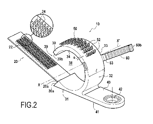
Figure 2 shows an attachment collar 10 constituting
an embodiment of the present invention.
The attachment collar 10 comprises a belt portion
30, which is C-shaped in this example, defining an open
inside space 38 for receiving elongate elements 300 that
are to be attached (see Figure 3), and including, on its
outside face 32, an array 50 of gripping elements 52.
The collar 10 also has a tape 20 secured to a first
free end 30a of the belt portion 30, its inside face 22
presenting retention elements 24 suitable for co-
operating with the gripping elements 52 of the belt
portion 30.
By folding the tape 20 towards the second free end
30b of the belt portion 30 and pressing its retention
elements 24 down to co-operate with the gripping elements
52, the belt portion 30 is closed and the elongate
elements 300 are retained in the inside space 38.
The belt portion 30 is made by injection molding a
thermoplastic material, in particular polyethylene,
polypropylene, polyamide, poly-ether-ether-ketone (PEEK),
polymethyl methacrylate (PMMA), polycarbonate (PC), or
polyester.
The material constituting the belt and the thickness
e of that material are selected so as to confer a certain
amount of stiffness thereto.
As shown in Figure 6, the belt portion 30 extends
over a reentrant angular sector of angle w that generally
lies in the range 220 to 300 . Thus, its two free ends
. CA 02849412 2014-03-20
,
7
30a, 30b remain angularly spaced apart from each other
even when it is closed in the above-described manner by
means of the tape 20.
In this example, the belt portion 30 presents an
inside profile in the form of a circular arc of axis
X-X'. Unless specified to the contrary, throughout the
description below, a direction is said to be "radial"
when it is perpendicular to the axis X-X' and intersects
the axis X-X', and a direction is said to be "axial" when
it is a direction parallel to the axis X-X'. More
generally, a radial direction is defined as being
perpendicular to a tangent to the belt portion.
As shown in Figure 2, the array 50 of gripping
elements provided on the belt portion 30 is an array of
hooks 52. Nevertheless, hooks 52 merely constitute a
non-limiting example of the present invention, and all of
the characteristics described below may apply in the same
manner to any other type of gripping element.
The hooks 52 are made by injection molding at the
same time as the belt portion 30 is made.
In order to make such a unit as a single piece in a
single molding operation, and given the difference in
volume of material between the belt portion 30 and the
hooks 52, it is preferable to use the installation and
the method as described in French patent application
No. 08/03707 filed on July 1, 2008 in the name of the
Applicant.
In this example, the array 50 of hooks is
constituted by a plurality of rows that extend axially.
Each row of hooks comprises a succession of single-headed
hooks 52 facing to the left and facing to the right.
As shown in Figure 2, the array 50 of hooks is
situated on the side of the belt portion 30 that is
remote from its end 30a to which the tape 20 is secured.
At this location, the outside profile of the belt portion
30 is curved, being centered on the axis X-X'.
= CA 02849412 2014-03-20
8
Over a zone starting from the first free end 30a of
the belt portion 30 that is furthest from the array 50 of
hooks, the outside face 31 of the belt portion 30 is on
the contrary substantially plane, so as to be capable of
bearing against a plane support 200, as shown in
Figures 6 and 7.
As shown in Figure 2, a fastener tab 40 extends from
this zone of the belt portion 30, tangentially
therethrough, and going away from the end 30a. A face 41
of the fastener tab 40 thus extends the plane outside
face 31 of the belt portion 30 and is situated in the
same plane.
The fastener tab 40 has a hole 42 for receiving a
screw 70 or any other element suitable for co-operating
with the support 200.
As shown in Figure 2, a safety clip 60 projects from
a zone of the belt portion 30 situated after the array 50
of hooks, going away from the second free end 30b of the
belt portion 30, i.e. between the array 50 of hooks and
the fastener tab 40. The zone of the belt portion 30
that carries the safety clip 60 presents a curved outside
profile in this example.
This safety clip extends from a first axial edge 33
of the belt portion 30. By means of a hinge 63 or merely
by means of folding, the safety clip 60 is suitable for
passing from a raised position in which it extends in a
direction that is substantially perpendicular to the
outside face 22 of the belt portion 30 (as shown in
Figures 2 and 3), to a displaced position in which its
free end 60b is displaced towards the opposite axial edge
34 of the belt portion 30 (as shown in Figure 4).
By way of example, the safety clip 60 may be molded
integrally with the belt portion 30. Under such
circumstances, and as shown in Figure 5, the hinge 63 may
be formed merely by a narrowing or a constriction of the
material.
CA 02849412 2014-03-20
9
In a variant embodiment, the safety clip 60 may be
sufficiently flexible to be folded into the pressed-down
position. Under such circumstances, there is no need to
provide a hinge.
In the example described, the safety clip 60
presents a length that is substantially equal to the
width e of the belt portion 30 so that in the pressed-
down position it covers the belt portion 30 from one
axial edge 33 to the other axial edge 34.
Still in the example described, the free end 60b of
the safety clip 60 co-operates with the opposite axial
edge 34 of the belt portion 30 by clip-fastening. For
this purpose, the safety clip 60 includes a tongue 61 at
its free end 60b for the purpose of occupying a position
facing the opposite axial edge 34 of the belt portion 30
once the safety clip 60 is in the pressed-down position.
This tongue 61 is terminated by a tooth 64 facing towards
the belt portion 30 and presenting a sloping surface
adapted to co-operate with a rib 35 provided on the axial
edge 34. When the tongue 61 is engaged against the rib
35 via the chamfered edge of the tooth 64, it flexes a
little and then, once the tooth 64 is engaged behind the
rib 35, it returns to its initial position. By blocking
the tooth 64, the rib 35 then prevents the safety clip 60
from moving away from the outside face 32 of the belt
portion 30.
Preferably, and as shown in Figure 4, the rib 35 is
provided in a setback 36 in the axial edge 34 of the belt
portion 30, thereby preventing the free end 60b of the
safety clip 60, once fastened in position, from sliding
tangentially relative to the belt portion 30.
As shown in Figure 5, the safety clip 60 has a
plurality of projecting portions in relief 62 on its face
that faces towards the belt portion 30, these portions in
relief having a function that is described in greater
detail below.
, CA 02849412 2014-03-20
As mentioned above, the tape 20 is secured to the
first free end 30a of the belt portion 30 that is
situated remote form the hook array 50.
The belt portion 30 is overmolded on the tape 20.
5 As shown in the figures, the width and the thickness of
the tape 20 are slightly smaller than the width and the
thickness of the belt portion 30 such that the proximal
end 20a of the tape 20 is completely embedded in the
plastics material of the belt portion 30.
10 In the example described, the tape 20 is made of
woven fabric. It is also provided on its inside face 22,
i.e. its face that faces towards the opening 39 in the
belt portion 30, with loops 24 that form retention
elements that are adapted to co-operate with the hooks 52
of the belt portion 30.
As shown in Figure 3, after the cables 300 have been
inserted into the inside space 38, the tape 20 is
displaced against the outside face 32 of the belt portion
30 so as to close the opening 39 (see arrow F1).
The tape 20 is pulled towards the belt portion 30 in
such a manner that at least some of the loops 24 are to
be found in register with the hook array 50 and can
become fastened thereto.
The safety clip 60 is then moved from its raised
position as shown in Figure 3 to its pressed-down
position as shown in Figure 4, and then the tongue 61 is
clipped onto the rib 35 of the belt portion 30. In this
position, the projecting portions in relief 62 apply
pressure spots on the tape 20 against the outside face 32
of the belt portion 30, thereby contributing to holding
it in place (see Figure 5).
The collar 10 is then releasably fastened on a
support 200 with the help of a screw 70, as shown in
Figure 6, of a staple as shown in Figure 7 or 8, of a
clip as shown in Figure 9, or of any other appropriate
fastener means.
CA 02849412 2014-03-20
11
The staple 71 shown in Figure 7 is particularly
suitable for fastening a collar 10 of the invention to a
foam panel made up of agglomerated beads of thermoplastic
material. Its Christmas-tree-shaped branches 72 define
between them interstices 73 in which one or more beads of
the panel can be housed.
The staple 74 shown in Figure 8 has a portion 75
that is to be clipped in the hole 42 in the fastener tab
40, and a wider base 76 that is provided on its bottom
face with hooks 77. This staple 74 is particularly
suitable for fastening onto a support 200 of non-woven
fabric.
Figure 9 shows a clip 78 adapted to be inserted in
the hole 42 of the fastener tab and then in a hole in a
support 200. The clip 78 has a head 79 adapted to bear
against the top face of the fastener tab 40, and two arms
80 that project from the bottom face of the head 79, the
arms having a pressed V-shape, each having a lug 81
projecting radially outwards. The arms 80 are adapted to
bend inwards while the lugs 81 are co-operating with the
inside wall of the hole in the support 200, and to
redeploy outwards once the lugs 81 have gone beyond said
hole, the lugs 81 then constituting means for preventing
the clip 78 from moving in translation relative to the
support 200.
Preferred dimensions for the collar of the invention
are given below.
Advantageously, the belt portion 30 presents at
thickness e lying in the range 1.5 millimeters (mm) to
3 mm. The hook array 50 extends over an angular sector z
of at least 450, and over a width lying in the range 6 mm
to 10 mm, and in any event greater than half the width of
the belt portion 30. The hook array 50 extends in all
over an area lying in the range 120 square millimeters
(mm2) to 180 mm2. It is made up of a plurality of
parallel rows of hooks that extend axially. In general,
the number of rows of hooks is selected to lie in the
CA 02849412 2014-03-20
12
range seven to 15. The distance dl measured linearly
between two similar points of two hooks 52 that are
immediately adjacent to each other and that occupy two
adjacent rows (see Figure 6) lies in the range 2 mm to
3 mm. The angular pitch between two adjacent rows of
hooks lies in the range 3 to 8 , for example.
In a particularly advantageous embodiment of the
invention, the belt portion 30 presents a circularly
arcuate shape with an outside radius r = 12.05 mm. Its
thickness e, i.e. the distance taken in the radial
direction between the inside face and the outside face of
the belt portion is equal to 2 mm. The hook array 50
extends in all over an angular sector of 90 , i.e. over
an arcuate length equal to 18.93 mm, and over a width
(taken in the axial direction) equal to 7.98 mm. The
total area of the hook array is then equal to 151 mm2.
The distance dl measured linearly between two similar
points of two hooks 52 that are immediately adjacent to
each other and that occupy two adjacent rows is equal to
2.31 mm. The angular pitch y between two adjacent rows
of hooks 52 is equal to 5 . With these arrangements, the
total volume of the part comprising the belt portion 30,
the safety clip 60, the hook array 50, and the fastener
tab 40 is equal to 2800 m3.