Note: Descriptions are shown in the official language in which they were submitted.
CA 02849978 2014-03-25
WO 2013/048902
PCT/US2012/056591
Method of Making Customized Devices and Kit
Field of the Invention
The present invention relates to a low-cost, handheld, electromechanical
personal body-care device having a one-piece housing and a unitary insert
including a frame and electromechanical elements disposed thereon. The
invention also relates to methods of making and assembling the devices and to
kits containing interchangeable components of such devices.
Background of the Invention
Handheld, electromechanical, personal body-care devices are known.
Many of these devices have mechanisms to transmit motion, such as vibration,
rotation, oscillation, and the like, to a body surface, such as a human face,
elbows, and/or feet.
Hull, Jr. et al., US Pat. No. 7,918,862, discloses a water-resistant device
incorporating a switch assembly. This is a typical example of an injection-
molded clamshell housing that includes structural features to permit
electromechanical elements to be mounted on the housing. In more detail, the
device includes a housing formed of a hard, lightweight plastic material,
which
may be formed of two portions and attached along a seam. In addition to this
seam between the housing portions, additional openings for a battery
compartment and power switch are formed in the housing. Each of these
openings employs a water-resistant seal.
Cowie et al., US Pat. Appl. No. 2010/0222719 purports to disclose a
facial care appliance having a tubular body containing electromechanical
elements. The tubular body is formed of mating, inter-fitting semi-cylindrical
sidewalls and has outer skins disposed thereon. Thus, this body requires
numerous seams to be sealed or gasketed if it is to be used in wet
environments to protect the internal electromechanical elements.
1
CA 02849978 2014-03-25
WO 2013/048902 PCT/US2012/056591
Despite the teaching of the prior art, there is a continuing need for skin
care devices that provide simple and reliable manufacture, reliable protection
against water damage, and potential for customization by the manufacturer or
user.
SUMMARY OF THE INVENTION
Therefore, we have discovered that separating the housing and the
electromechanical elements of a handheld personal body-care device
increases manufacturing flexibility, reduces manufacturing costs, and reduces
potential for the undesired ingress of liquids.
In particular, a method of making a handheld, electromechanical device
useful in mammalian body-care includes the steps of: a) forming a one-piece
housing having a single opening defined by a rim; b) selecting a unitary
insert;
c) inserting the selected unitary insert through the single opening of the
housing d) selecting, from a plurality of different covers; e) removably
applying
the selected cover to close the opening of the housing; and f) attaching the
unitary insert to at least one of the one-piece housing and the removable
cover.
The rim of the one-piece housing circumscribes a rim area and the one-piece
housing has a projected area that is substantially larger than the rim area.
The
unitary insert is selected from a plurality of different unitary inserts, and
each
unitary insert has a frame having disposed thereon electromechanical elements
interconnected in an electrical circuit. The selected cover is arranged and
configured to cooperate with the selected unitary insert, and each of the
plurality of different covers is arranged and configured to cooperate with one
or
more of the plurality of different unitary inserts.
In another embodiment, a method of assembling a handheld,
electromechanical device useful in mammalian body-care from a kit having
interchangeable components includes the steps of: a) selecting as a first
component a one-piece housing having a single opening defined by a rim; b)
selecting as a second component a unitary insert dimensioned to be insertable
through the opening defined by the rim; c) inserting the selected unitary
insert
2
CA 02849978 2014-03-25
WO 2013/048902 PCT/US2012/056591
through the single opening of the housing; d) selecting as a third component a
removable cover arranged and configured to cooperate with the selected
unitary insert; e) removably applying the selected cover to close the opening
of
the housing; and f) attaching the unitary insert to at least one of the one-
piece
housing and the removable cover. The rim of the housing circumscribes a rim
area and the one-piece housing has a projected area that is substantially
larger
than the rim area. The unitary insert has a frame having disposed thereon
electromechanical elements interconnected in an electrical circuit. The kit
includes at least one of each of the first, second, and third components and a
plurality of at least one of the components. Finally, each of the first,
second,
and third components selected are arranged and configured to cooperate with
the other selected components.
In another embodiment, a kit has interchangeable components for
customizing a handheld, electromechanical device useful in mammalian body-
care. The kit includes a first component comprising a one-piece housing
having a single opening defined by a rim. The rim circumscribes a rim area
and the one-piece housing has a projected area that is substantially larger
than
the rim area. A second component of the kit includes a unitary insert
dimensioned to be insertable through the opening defined by the rim. The
unitary insert has a frame having disposed thereon electromechanical elements
interconnected in an electrical circuit. A third component of the kit includes
a
removable cover arranged and configured to cooperate with the selected
unitary insert. The kit includes at least one of each of the first, second,
and
third components and a plurality of at least one of the components. Each of
the
first, second, and third components selected are arranged and configured to
cooperate with the other selected components.
BRIEF DESCRIPTION OF THE DRAWINGS
Fig. 1 is a perspective view of one embodiment of the device of the
present invention.
Fig. 2 is a side elevation of the housing of Fig. 1.
3
CA 02849978 2014-03-25
WO 2013/048902 PCT/US2012/056591
Fig. 3 is a top view of the housing of Fig. 1 showing the projected area of
the housing.
Fig. 4 is an exploded, side elevation of the device of Fig. 1.
Fig. 5 is a detailed view of the unitary insert of Figs. 1 and 4.
Fig. 6 is an exploded, side elevation of an alternative embodiment
having a unitary insert with a modified distal end.
Fig. 7 is a perspective view of the cover and housing/insert of Figs. 1-5
with the cover separated from the housing/insert and rotated to show the
underside of the cover.
Fig. 8 is an exploded, perspective view of the cover and housing of an
embodiment of the present invention having a cover in the form of a plug.
Fig. 9 is a partial cross-section of an embodiment of the present
invention having a shaft disposed through the cover.
Fig. 10 is a partial cross-section of the housing and insert of an
embodiment of the present invention having a gasket disposed between the
insert and the housing.
Fig. 11 is a side elevation of a preform useful in blow-molding the one-
piece housing of Fig. 2.
Fig. 12 is a schematic view of components of a kit comprising multiple
unitary inserts and one-piece housings according to an embodiment of the
present invention.
DETAILED DESCRIPTION OF THE PREFERRED EMBODIMENTS
A review of the prior art described above suggests that elegant, simple
solutions to water resistant electromechanical personal body-care devices are
still needed. In particular, plastic housings are often two-piece, injection-
molded clam shell structures. This provides ease in manufacturing with
4
CA 02849978 2014-03-25
WO 2013/048902 PCT/US2012/056591
structural elements extending from the interior surface of the housing that
form
mounting surfaces for electromechanical elements contained therein.
However, as the electromechanical elements are changed during the evolution
of a commercial product, either the injection mold must be modified, or there
are significant structural limitations on the design evolution. Alternatively,
changes in the housing must be designed in conjunction with the mounting of
the electromechanical elements. In addition, mounting electromechanical
elements directly on the housing provides direct pathways to transfer
undesired
motion to the gripping surfaces of the housing. Finally, combining multiple
plastic pieces together to form a unitary housing requires additional
locations to
seal the structure from the possible ingress of liquids, such as water.
Therefore, we have separated the housing and the electromechanical
elements to increase manufacturing flexibility, reduce manufacturing costs,
and
to reduce potential for the undesired ingress of liquids. In particular, we
have
invented a low-cost, handheld, water-resistant electromechanical, personal
body-care device that has a one-piece housing and a single opening defined by
a rim, a unitary insert dimensioned to be insertable through the opening, and
a
removable cover arranged and configured to engage the rim. The unitary insert
includes a frame having disposed thereon electromechanical elements
interconnected in an electrical circuit. The removable cover has an exterior
surface, and it is arranged and configured to transmit at least one output of
the
electromechanical elements disposed within the housing.
As used herein the specification and the claims, the term "unitary" and
variants thereof means a collection of parts joined to form a whole.
As used herein the specification and the claims, the term "rim" and
variants thereof means the edge of a structure defining an opening, which may
be circular or other geometric shape.
As used herein the specification and the claims, the term "projected
area" and variants thereof means the area of the projection of a three-
dimensional object onto a plane. When two or more projected areas are
compared, the projection is onto the same plane.
5
CA 02849978 2014-03-25
WO 2013/048902 PCT/US2012/056591
As used herein the specification and the claims, the term "removable
cover" and variants thereof relates to covers that are designed to be applied
to
close the opening of the one-piece housing and to be removable therefrom
without undue effort and/or damage to any of the cover, unitary insert, and
one-
piece housing.
As shown in Fig. 1, a first embodiment of the device of the present
invention is a handheld, water-resistant electromechanical device 10 useful in
mammalian personal body-care. The device includes a one-piece housing 20
containing a unitary insert 30 and having a cover 40. Preferably, the one-
piece
housing 20, the unitary insert 30, and the cover 40 are arranged and
configured
to resist the ingress of liquids into the device. This may be done by
selective
use of gaskets, as described below. Thus, the device can better resist the
ingress of liquids into the device. In addition, the unitary insert 30 is
attached to
at least one of the one-piece housing 20 and the cover 40 to provide a more
robust device.
As shown in Fig. 2, the one-piece housing 20 defines a volume
contained by the housing, and it has a single opening 21 defined by a rim 22.
The one-piece housing preferably has an ergonomic shape that facilitates
holding by a human hand. The handheld electromechanical device is light-
weight to prevent user fatigue during use. Preferably, the handheld,
electromechanical device has a mass of less than about 450 grams; more
preferably, less than about 300 g; and most preferably, less than about 150g.
The one-piece housing 20 has a substantially continuous exterior wall to
provide a pleasing appearance and to eliminate the risk of poorly closed seams
between housing components present in multi-part housings that can provide
pathways for the ingress of liquids into the device. The single opening
greatly
reduces the number of and linear dimension(s) of seams in the construction of
the electromechanical device. It may be desirable to provide a shoulder 23
proximate the opening 21. Thus, the rim 22 can extend from the shoulder 23 to
permit the cover 40 to engage and fit over the rim 22 in this embodiment. A
gasket 24 may be disposed about the rim 22. As shown in Figs. 2 and 10, the
gasket 24 is an o-ring, and it is disposed in a groove 25 dimensioned to
provide
6
CA 02849978 2014-03-25
WO 2013/048902 PCT/US2012/056591
an effective, sealing seat for the gasket 24 to prevent the ingress of liquids
into
the device 10. While a circular opening and corresponding rim are shown in
Figs. 1-5, it will be recognized that alternative geometric shapes are
possible.
The one-piece housing 20 preferably has an interior surface that is
substantially smoothly continuous for ease of manufacture and for improved
mechanical isolation of the unitary insert 30 from the housing 20. This
smooth,
continuous interior surface also necessitates assembly of electromechanical
elements on the frame of the unitary insert, as discussed in greater detail,
below. As shown in Fig. 3, the one-piece housing 20 has a projected area PAH
(shown by cross-hatching within bold outside line defining the periphery of
the
projection) that is substantially larger than the rim area RA (shown by
opposite
cross-hatching within the opening), the area circumscribed by the rim 22. In
this embodiment, the projected area PA is symmetrical on opposite sides of a
plane perpendicular to the rim 22, although it is not radially symmetrical
about
the center of the rim 22. In alternative embodiments, the projected area may
be radially symmetrical about a center of the opening 21, symmetrical across
multiple planes perpendicular to the rim, or it may be isotropic (having a
structural independent of the direction from the center or diameter of the
opening).
The outer surface of the one-piece housing may be smooth or it may
have surface features, such as highlighted gripping area 26. The surface
features may be formed during the formation of the one-piece housing or they
may be added later. These surface features may include without limitation,
texturing, coloring, information, etc. The surface features may be provided
through known methods, such as by coating (e.g., printing, and/or painting),
applying labels or other structures, etching, dyeing, and the like. Texturing
may
be slight or it may be substantial enough to be noticeable on the interior
surface
of the housing. The one-piece housing can be transparent in order to be able
to see the internals. This is useful for using LED's internally as status
indicators. Housing is preferably rigid, although it may be helpful to have
one
or more flexible portions. Alternatively, the one-piece housing may be more
flexible. The partial or complete flexibility may be useful to incorporate a
switch
7
CA 02849978 2014-03-25
WO 2013/048902 PCT/US2012/056591
that the user can depress by flexing the housing (same applies for the cap) or
having a pump for dispensing liquids through. Gaskets protect the ingress of
liquids from the exterior, but in another embodiment can be used to protect
liquids from exiting.
Fig. 4 shows an exploded, side elevation of the device of Fig. 1 to show
the relationship between the one-piece housing 20, the unitary insert 30, and
the cover 40, and Fig. 5 provides additional details of the unitary insert 30
and
its constituent elements. Again, the unitary insert 30 includes a frame 31
having disposed thereon electromechanical elements interconnected in an
20 below.
The unitary insert 30 is dimensioned to be insertable through the
opening 21 and to be substantially contained within the one-piece housing 20.
In the embodiment of Figs. 1-5, the unitary insert 30 has a projected area PAI
that is circumscribed by the rim 22 (see Fig. 4). It should be noted that this
8
CA 02849978 2014-03-25
WO 2013/048902 PCT/US2012/056591
a remaining portion of the unitary insert that has a projected area that is
circumscribed by the rim, and inserting the remaining portion of the unitary
insert 30' through the rim 21.
The removable cover 40 engages the rim 22 to close the opening 21. In
the embodiment of Figs. 1-5, the removable cover 40 is a cap that is arranged
and configured for removable engagement over the rim 22. The cap also
engages the gasket 24 disposed about the rim 22 to prevent the ingress of
liquids into the device 10. This sealing engagement protects the
electromechanical elements from damage, including short-circuiting, that water
or other liquids may cause if it were to penetrate into the interior of the
housing
20. In the embodiment of Figs. 1-5 and 7 and also in the embodiment of Fig.
10, discussed in greater detail, belowõ the cap has an inner surface 41
disposed toward the unitary insert 30 that closes the opening 21, and an
exterior surface 42 disposed away from the opening 21. In addition, the cap
has sidewalls 43 that encircle the rim 22 and engage the gasket 24. The
exterior surface 42 may itself be a body-care surface, or it may be a platform
or
other structure on which optional, body-care elements, 44 may be disposed,
either directly on the exterior surface 42 or through an optional coupler 44a
such as disclosed in commonly assigned, Hull, US Serial No.12/770,994, filed
April 30, 2010. Such optional, body-care element may be applied directly on
the optional coupler 44a or onto the exterior surface, or there may be an
attachment mechanism, such as a hook-and-loop system, or adhesives,
clamps, snaps, and the like.
In the preferred embodiment show in Figs. 1-5, the cover cooperates
with the insert to form a switch. This is shown in more detail in Fig. 7. The
unitary insert 30 has a first electrical conductor 37a disposed on its
proximal
surface 32a, and the inner surface 41 of the cap has a second electrical
conductor 37b. The cap is preferably engaged with the rim 22 via a bayonet
connector mechanism with one or more pins disposed on the frame and
matching "L" slots disposed in the inner walls 43 of the cap. The cap and/or
rim
are formed of a sufficiently resilient material to permit the cap and rim to
be
removable locked together. In this embodiment, the "L" slot is extended to
9
CA 02849978 2014-03-25
WO 2013/048902 PCT/US2012/056591
permit the cap to rotate between (1) an "on" position in which the second
electrical conductor 37b on the cap connects the first electrical conductor
37a
disposed on the proximal surface 32a of the unitary insert 30 and the battery
36
to close the electrical circuit and (2) an "off' position in which the second
electrical conductor 37b on the cap is rotated to break the electrical circuit
by
disengaging either or both of the first electrical conductor 37a on the
unitary
insert 30 and battery 36.
Although the previous paragraph described a bayonet coupling between
the cover 40 and insert 30, the elements of the bayonet coupling such as the
pins and slots can be located on combinations of housing 20, the unitary
insert
30, and the cover 40.
Another embodiment may replace the rotating switch formed by the
combination of the cover 40 and the insert 30 with a push-button switch
operated by flexing the housing and/or cover.
In an alternative embodiment shown in Fig. 8, the cover is a plug 40' that
is arranged and configured for removable engagement within the rim 22'. A
gasket 45 such as an o-ring may be disposed about the plug 40'. Again, the o-
ring may be disposed in a groove dimensioned to provide an effective, sealing
seat for the gasket 45 to prevent the ingress of liquids into the device 10.
In a further alternative embodiment shown in Fig. 9, the cover 40" may
have an aperture 46 having a shaft gasket 47 and a moveable shaft 48
disposed therein, and wherein the moveable shaft 48 is operatively connected
to the motor 35 mounted on the insert to transfer motion from the motor 35 to
a
moving platform 49 having body-care element 44 disposed thereon outside of
the housing 20. Thus, the body-care element 44 may rotate or oscillate against
the user's skin. Other motion outputs are also possible. For example, cams,
slides, and/or other translational mechanisms may interact with the moving
platform 49.
As mentioned above, it is desirable to construct the body-care device 10
to resist the ingress of liquids into the device to avoid damage to the
electrical
components contained therein. Thus, the housing 20 sealingly engages with at
CA 02849978 2014-03-25
WO 2013/048902
PCT/US2012/056591
least one of the unitary insert 30 and cover 40. The use of one or more
gaskets 24, 45 between the cover 40 and the housing 20 are described above.
In addition or in place of such gaskets, it may be desirable to seal the
connection between the housing 20 and the unitary insert 30. Thus, an
appropriate gasket 38 may be disposed between the housing 20 and the
unitary insert 30, as shown in Fig. 10. This gasket 38 may simply resist the
ingress of liquids into the interior of the housing 20, or it may also act as
a
damping member to dampen movement generated by the electromechanical
elements disposed on the frame 31 and isolate it from transfer to the housing
20. However, if one determines that water-resistance is not critical to the
operation of the device, one or more of the gaskets can be eliminated.
As can be seen in a review of the foregoing paragraphs, cover 40 is
arranged and configured to transmit at least one output of the
electromechanical elements disposed within the housing. For example, in the
embodiment of Figs. 1-5, vibratory motions from the insert 30 may be
transferred through the cover 40 to the exterior surface 42. In the embodiment
of Fig. 9, rotating or oscillating motion from the insert may be transferred
through the cover 40" via moveable shaft 48 to a skin-contacting element 48.
In the embodiment of Fig. 10, the vibratory motions from the insert 30 may be
isolated from the housing 20 and transferred directly to a skin-contacting
element 48.
As discussed above, the one-piece housing 20 defines a volume
contained by the housing. When the opening 21 is closed by the cover 40, the
volume contained by the one-piece housing is at least about 60(Yoof the total
volume contained by the one-piece housing 20 and the cover 40. Preferably,
the volume contained by the one-piece housing is at least about 80%, and
more preferably at least about 90% of the total volume contained by the one-
piece housing 20 and the cover 40.
The device of the present invention is made by forming a one-piece
housing, assembling a unitary insert, inserting the unitary insert into the
housing, attaching the unitary insert to the one-piece housing, and removably
applying a cover to the housing. Again, the one-piece housing defines a
11
CA 02849978 2014-03-25
WO 2013/048902 PCT/US2012/056591
volume and has a single opening defined by a rim. The housing also has a
substantially continuous exterior wall, and it has a projected area that is
substantially larger than the rim. Preferably, the housing has a shoulder, and
the rim extends above the shoulder. The rim may also have a gasket disposed
thereabout. Thus, the device may be made by forming a one-piece housing
having an opening defined by a rim and arranging a gasket about the rim.
The one-piece housing may be formed by blow-molding a thermoplastic
preform to the desired final form. Those of ordinary skill in the art will
recognize
how to design the preform dimensions to result in the desired final form. For
example, the one-piece housing 20 shown in Fig. 2 may result from blow-
molding a thermoplastic preform 50 shown in Fig. 10. The preform 50 has
elements of the rim 22, such as the groove 25 already molded into it. These
elements are maintained during the blow-molding process.
The blow-molding process provides a one-piece housing having a
substantially continuous exterior wall with an interior surface that is
substantially smoothly continuous. Alternative molding processes include
rotomolding. Again, these processes permit the formation of final housing
shapes in which the projected area PA is symmetrical on opposite sides of one
or more planes perpendicular to the rim 22, symmetrical about a center of the
opening 21, and/or isotropic. In marked contrast to injection molding, the
blow-
molding process also permits the simple formation of desired one-piece
housings having a projected area that is substantially larger than the rim. In
cases in which the one-piece housing material is subjected to conditions that
may potentially alter the dimensions of the opening and/or rim ¨ structures
that
are significant to sealing engagement of the components of the device ¨ it may
be useful to incorporate structures to maintain these dimensions during the
manufacturing process. For example, the process equipment may include
elements that maintain the diameter of the rim after the formation of the
preform, during the blow-molding process, and during a cool-down period after
the one-piece housing is complete.
The unitary insert again includes a frame having disposed thereon
electromechanical elements interconnected in an electrical circuit. The frame
12
CA 02849978 2014-03-25
WO 2013/048902 PCT/US2012/056591
may be formed of one or more structural elements, preferably plastic, that may
be formed by any means available. For example, one or more elements of the
frame may be injection molded plastic components that form mounting surfaces
for a motor or other motion-generating devices, a battery or other power
sources, gears, shafts, etc. The frame may also have disposed thereon
electrical connectors and one or more switches or switch elements. The
individual components of the unitary insert are joined together to form the
complete unitary insert. This is inserted through the single opening of the
housing and attached thereto. As discussed above, the unitary insert 30 (such
as shown in Fig. 4) may be inserted into the one-piece housing 20 using a
single, linear motion. Alternatively, as shown in Fig. 6, the method may
require
that a distal portion 33' of the unitary insert be aligned with the opening,
inserting the distal portion through the opening, pivoting the unitary insert
to
align a remaining portion of the unitary insert that has a projected area that
is
circumscribed by the rim, and inserting the remaining portion of the unitary
insert through the rim.
Optionally, a gasket and/or damping member may be disposed between
the unitary insert and the housing to further protect the electromechanical
elements from the ingress of liquids and/or to inhibit the transfer of motion
between the unitary insert and the housing.
The method also includes removably applying a cover to the housing to
cover the opening thereof. In one embodiment, the cover is a cap, and the step
of removably applying the cover comprises removably engaging the cap over
the rim. In another embodiment, the cover is a plug, and the step of removably
applying the cover comprises removably engaging the plug within the rim. If
the cover is a plug, the method may include the step of arraigning a gasket
about the plug.
The unitary insert 30 is attached to at least one of the one-piece housing
20 and the cover 40 to provide a more robust device. The attachment may be
permanent or it can be temporary or detachable. The attachment can be done
through known methods including without limitation, welding, adhesives, and
mechanically fastening (screw, snap, interference fit, and the like). In
several
13
CA 02849978 2014-03-25
WO 2013/048902 PCT/US2012/056591
preferred embodiments, the unitary insert is ultrasonically welded to either
the
cover or the one-piece housing.
The devices of the present invention can be used for any desired body-
care regimen. Known regimens include cleansing, exfoliating,
microdermabrasion, massage, and the like. In embodiments incorporating
optional body-care elements, a user may select an appropriate body-care
element, apply it to the exterior surface of the cover, apply water to the
body-
care element (if appropriate), activate the motion of the device, and apply
the
body-care element to desired locations. After use, the body-care element may
be removed and discarded. Thus, the body-care elements may be in the form
of pads, brushes, sponges, poufs (gathered nets of polymeric material),
protrusions (for massaging, etc.), and the like.
Another method of the present invention relates to a method of making
handheld electromechanical devices and/or permitting a user to select
components of a handheld mechanical device body-care system. The method
includes the steps of forming a one-piece housing defining a volume and
having a single opening defined by a rim, selecting a unitary insert
dimensioned
to be insertable through the opening defined by the rim from a plurality of
unitary inserts, inserting the selected unitary insert through the single
opening
of the housing and attaching the insert to the one-piece housing, selecting,
from a plurality of covers, a cover arranged and configured to cooperate with
the selected unitary insert, and removably applying the cover to close the
single
opening of the housing. Each of the plurality of unitary inserts includes a
frame
having disposed thereon electromechanical elements interconnected in an
electrical circuit. The each plurality of different covers is arranged and
configured to cooperate with one or more of the plurality of different unitary
inserts.
The one-piece housing may be of any shape, or selected from among a
plurality of shapes and sizes and surface features, as long as it is suitable
for
handheld, consumer use. Additionally, the plurality of unitary inserts may be
selected from a supply of unitary inserts having different electromechanical
elements, sizes, and/or shapes. Thus, the desired unitary insert may provide
14
CA 02849978 2014-03-25
WO 2013/048902 PCT/US2012/056591
different motion, different power levels, and other different properties, as
desired by consumers. The plurality of covers may be selected from a supply
that are arranged and configured to cooperate with the various one-piece
housings and unitary inserts. These covers may be caps, plugs, and the like,
as described above.
Therefore, this method provides flexibility for manufacturers to provide
customizable and/or a variety of handheld electromechanical devices on a
single manufacturing line. Alternatively, it permits the creation of kits of
body-
care devices and inter-changeable elements for consumers to have a variety of
customizable configurations in their homes.
As described above, at least two of the one-piece housing, unitary insert,
and cover are preferably sealing engaged to resist the ingress of liquids
intot he
one-piece housing. This may be achieved by arranging a gasket about the rim,
about the cover, and/or between the unitary insert and the one-piece housing.
In addition, the damping member described above may be provided between
the unitary insert and the one-piece housing.
The kit having interchangeable components includes a first component
that is a one-piece housing, a second component that is a unitary insert, and
a
third component that is a cover. The kit includes at least one of each of the
first, second, and third components, and at least two of one of the
components.
Thus, the kit may include one one-piece housing and multiple unitary inserts
and corresponding covers, or the kit may include one unitary insert and
multiple
one-piece housings and corresponding covers. While it may also be possible
to have one cover and multiple one-piece housings and unitary inserts, this is
likely to be rather uncommon. Finally, the kit may include a plurality of each
of
the three components.
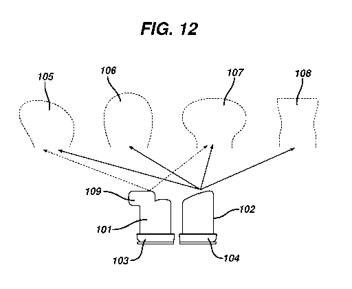
An example of a kit is shown in Fig. 12. The kit contains two unitary
inserts 101, 102. Each unitary insert 101, 102 has associated therewith a
cover 103, 104, respectively. The combination unitary insert/cover can be
combined with one of four one-piece housings 105, 106, 107, 108 (shown in
phantom cross-section). However, unitary insert 101 has a lateral extension
CA 02849978 2014-03-25
WO 2013/048902 PCT/US2012/056591
109 on its distal end, and this extension interferes with the two of the one-
piece
housings. Therefore, this unitary insert 101 can be used only with one-piece
housings 105, 107 and not with one-piece housings 108, 109 (as indicated by
the arrows connecting the unitary insert and housings.
The specification and embodiments above are presented to aid in the
complete and non-limiting understanding of the invention disclosed herein.
Since many variations and embodiments of the invention can be made without
departing from its spirit and scope, the invention resides in the claims
hereinafter appended.
16