Note: Descriptions are shown in the official language in which they were submitted.
CA 02850226 2014-03-26
Charger Alignment in an Implantable Medical Device System
Employing Reflected Impedance Modulation
FIELD OF THE INVENTION
[003] The present invention relates to wireless external chargers for use in
implantable medical device systems.
BACKGROUND
[004] Implantable stimulation devices are devices that generate and deliver
electrical stimuli to body nerves and tissues for the therapy of various
biological
disorders, such as pacemakers to treat cardiac arrhythmia, defibrillators to
treat
cardiac fibrillation, cochlear stimulators to treat deafness, retinal
stimulators to
treat blindness, muscle stimulators to produce coordinated limb movement,
spinal
cord stimulators to treat chronic pain, cortical and deep brain stimulators to
treat
motor and psychological disorders, and other neural stimulators to treat
urinary
incontinence, sleep apnea, shoulder sublaxation, etc. The description that
follows
will generally focus on the use of the invention within a Spinal Cord
Stimulation
(SCS) system, such as that disclosed in U.S. Patent 6,516,227. However, the
present invention may find applicability in any implantable medical device
system.
[005] As shown in Figures 1A-1C, a SCS system typically includes an
Implantable Pulse Generator (IPG) 100, which includes a biocompatible device
case 30 formed of a conductive material such as titanium for example. The case
30 typically holds the circuitry and battery 26 necessary for the IPG to
function,
although IPGs can also be powered via external RF energy and without a
battery.
1
CA 02850226 2014-03-26
WO 2013/055526
PCT/US2012/057582
The IPG 100 is coupled to electrodes 106 via one or more electrode leads (two
such leads 102 and 104 are shown), such that the electrodes 106 form an
electrode
array 110. The electrodes 106 are carried on a flexible body 108, which also
houses the individual signal wires 112 and 114 coupled to each electrode. In
the
illustrated embodiment, there are eight electrodes on lead 102, labeled El-Es,
and
eight electrodes on lead 104, labeled E9-E16, although the number of leads and
electrodes is application specific and therefore can vary. The leads 102, 104
couple to the IPG 100 using lead connectors 38a and 38b, which are fixed in a
non-conductive header material 36, which can comprise an epoxy for example.
[006] As shown in the cross-section of Figure 1C, the IPG 100 typically
includes
an electronic substrate assembly including a printed circuit board (PCB) 16,
along
with various electronic components 20 mounted to the PCB 16, some of which are
discussed subsequently. Two coils (more generally, antennas) are generally
present in the IPG 100: a telemetry coil 13 used to transmit/receive data
to/from
an external controller (not shown); and a charging coil 18 for charging or
recharging the IPG's battery 26 using an external charger 50 (discussed
further
below). In this example, the telemetry coil 13 and charging coil 18 are within
the
case 30, as disclosed in U.S. Patent Publication 2011/0112610. (Fig. 1B shows
the IPG 100 with the case 30 removed to ease the viewing of the two coils 13
and
18). However, the telemetry coil 13 may also be mounted within the header 36
of
the IPG 100 (not shown).
[007] Figure 2 shows the IPG 100 in communication with external charger 50
just
mentioned. The external charger 50 is used to wirelessly convey power to the
IPG
100, which power can be used to recharge the IPG's battery 26. The transfer of
power from the external charger 50 is enabled by a coil (antenna) 17. The
external charger 50, like the IPG 100, also contains a PCB 70 on which
electronic
components 72 are placed. Again, some of these electronic components 72 are
discussed subsequently. A user interface 74, including touchable buttons and
perhaps a display and a speaker, allows a patient or clinician to operate the
external charger 50. A battery 76 provides power for the external charger 50,
which battery 76 may itself be rechargeable. The external charger 50 can also
receive AC power from a wall plug. A hand-holdable case 77 sized to fit a
user's
2
CA 02850226 2014-03-26
WO 2013/055526
PCT/US2012/057582
hand contains all of the components.
[008] Power transmission from the external charger 50 to the IPG 100 occurs
wirelessly, and transcutaneously through a patient's tissue 25, via inductive
coupling. Figure 3 shows details of the circuitry used to implement such
functionality. Coil 17 in the external charger 50 is energized via charging
circuit
122 with a constant non-data-modulated AC current, Icharge, to create an AC
magnetic charging field. This magnetic field induces a current in the charging
coil
18 within the IPG 100, which current is rectified (132) to DC levels, and used
to
recharge the battery 26, perhaps via a charging and battery protection circuit
134
as shown. The frequency of the magnetic charging field can be perhaps 80 kHz
or
so. When charging the battery 26 in this manner, is it typical that the case
77 of
the external charger 50 touches the patient's tissue 25, although this is not
strictly
necessary.
[009] The IPG 100 can also communicate data back to the external charger 50
during charging using reflected impedance modulation, which is sometimes
known in the art as Load Shift Keying (LSK). Such back telemetry from the IPG
100 can provide useful data concerning charging to the external charger 50,
such
as the capacity of the battery 26, or whether charging is complete and the
external
charger 50 can cease.
[0010] Control circuitry 140 in the IPG 100 monitors the battery voltage,
Vbat,
and with the assistance of LSK module 155, produces LSK data. The control
circuitry 140 can include a microcontroller for example, and may be associated
with Analog-to-Digital (A/D) conversion circuitry to process and interpret the
battery voltage. LSK module 155 preferably operates as software in the control
circuitry 140, and assesses the incoming battery voltage to produce
appropriate
LSK data at appropriate times. Such LSK data is sent as a serial string of
bits
along line 99 to the gates of load transistors 141 and 142. The LSK data
modulates
the state of transistors 141 and 142, which in turn modulates the impedance of
the
coil 18. When LSK data=1, the transistors 141 and 142 are on (shorted) which
shorts each end of the coil 18 to ground. When LSK data=0, the transistors are
off
(opened). The impedance of the coil 18 may also be modulated by a single
transistor in series with the coil 18, which modulates the impedance by
opening
3
CA 02850226 2014-03-26
WO 2013/055526
PCT/US2012/057582
the coil, as shown in dotted lines.
[0011] Such modulation of the charging coil 18 is detectable at the external
charger 50. Due to the mutual inductance between the coils 17 and 18, any
change in the impedance of coil 18 affects the voltage needed at coil 17,
Vcoil, to
drive the charging current, Icharge: if coil 18 is shorted (LSK data=1), Vcoil
increases to maintain Icharge; if not shorted (LSK data=0), Vcoil decreases.
In
this sense, the impedance modulation of coil 18 is "reflected" back to the
transmitting coil 17, and thus data can be said to be "transmitted" from the
IPG
100 to the external charger 50, even if not transmitted in the traditional
sense. An
example Vcoil waveform arising from transmission of an example sequence (LSK
data=01010) is shown at the bottom of Figure 3, and shows the data states as
modulated by the ¨80 kHz frequency of the magnetic field.
[0012] The Vcoil waveform is processed at demodulation circuitry 123 to
recover
the transmitted LSK data. To be reliably detected, the difference in coil
voltage
(AV) between the transmitted '0' (Vcoilo) and '1' (Vcoili) states must as a
practical matter be greater than a threshold voltage inherent in the
demodulator
123, Vtl. Depending on the particularly of the circuitry, Vtl can be rather
small,
ranging from 50 mV to 100 mV for instance, and can be statistically determined
based on suitable bit error rates for LSK transmission.
[0013] The serial stream of demodulated bits is then received at control
circuitry
144 operating in the external charger 50, so that appropriate action can be
taken.
The control circuitry 144 can again include a microcontroller for example. For
example, if an alternating stream of bits is received (01010101...), this
might be
interpreted by the control circuitry 144 that the battery 26 in the IPG 100 is
full,
and therefore that charging can cease. In such an instance, the control
circuitry
144 can suspend the production of the magnetic charging field (i.e., setting
Icharge to 0), and may notify the user of that fact (by a graphical display,
an
audible beep, or other indicator).
[0014] Because LSK telemetry works on a principle of reflection, LSK data can
only be communicated from the IPG 100 to the external charger 50 during
periods
when the external charger is active and is producing a magnetic charging
field.
[0015] An issue arising when inductive coupling is used for power transmission
4
CA 02850226 2014-03-26
WO 2013/055526
PCT/US2012/057582
relates to the coupling between the coils 17 and 18 in external charger 50 and
the
IPG 100. Coupling, generally speaking, comprises the extent to which power
expended at the transmitting coil 17 in the external charger 50 is received at
the
coil 18 in the IPG 100. It is generally desired that the coupling between
coils 17
and 18 be as high as possible: higher coupling results in faster charging of
the IPG
battery 26 with the least expenditure of power in the external charger 50.
Poor
coupling is disfavored, as this will require high power drain (i.e., a high
Icharge)
in the external charger 50 to adequately charge the IPG battery 26. The use of
high power depletes the batteries 76 (if any) in the external charger 50, and
more
importantly can cause the external charger 50 to heat up, and possibly burn or
injure the patient.
[0016] Coupling depends on many variables, such as the permeability of the
materials used in the external charger 50 and the IPG 100, as well materials
inherent in the environment. Coupling is also affected by the relative
positions of
the external charger 50 and IPG 100, as shown in Figures 4A-4D. For best
coupling, it is preferred that axes around which coils 17 and 18 are wound
(17'
and 18') are parallel and collinear, and that the coils 17 and 18 as close as
possible
(dl) to each other, as shown in Figure 4A. Distance dl indicates the depth
between the external charger 50 and the IPG 100, and is generally constant
given
that the external charger is generally placed on the patient's tissue 25, and
that the
IPG 100 has been implanted at a particular depth. Deviations from these ideal
conditions will generally reduce coupling, as shown in Figures 4B-4D. In
Figure
4B for instance, the coil axes 17' and 18' are not collinear, but instead are
laterally
offset (x). In Figure 4C, the coil axes 17' and 18' are not parallel, but
instead
have an angle 0 between them. In Figure 4D, the coil axes 17' and 18 are
parallel
and collinear, but the IPG 100 is relatively deep (d2).
[0017] In any of these non-ideal cases 4B-4D, coupling will be reduced,
meaning
that the external charger 50 must output more power (e.g., Icharge must be
higher)
to affect the same charging rate of the IPG's battery 26. Some of these non-
idealities cannot be avoided after implantation: for example, if the IPG 100
is
deeply implanted (Fig. 4D), or implanted at an angle (Fig. 4C), poor coupling
with
the external charger 50 may be unavoidable.
CA 02850226 2014-03-26
WO 2013/055526
PCT/US2012/057582
[0018] However, poor lateral placement (Fig. 4B) can be improved by the user
by
moving the external charger 50 into better alignment with the IPG 100 during
production of the magnetic charging field. In this regard, the art has taught
different means of detecting and indicating such lateral misalignment to the
user.
Generally, the control circuitry 144 in the external charger 50 indicates
misalignment to a user via an alignment indicator 162. Often, the alignment
indicator 162 comprises a speaker for issuing an audible indication such as a
"beep" for example when the external charger 50 is misaligned with the IPG
100.
(Alternately, a "beep" could indicate an aligned condition). Alignment
indicator
162 can also comprise a visual indicator such as a display or a lamp (e.g., an
LED)
on the external charger 50, or a tactile indicator such as a vibration motor
that
causes the external charger 50 to vibrate. (An audible or tactile indication
would
be preferred if the external charger 50 isn't easily viewed by the patient
during a
charging session). Upon hearing, seeing, or feeling (or failing to see, hear,
or feel)
such an indication, the user of the external charger 50 can use his or her
hand to
then laterally shift the position of the external charger 50 around until
better
alignment is achieved, and the indicator ceases (or issues).
[0019] However, many prior alignment approaches are complicated, requiring
significant and expensive modifications to the external charger 50. For
example,
in some techniques, information relevant to coupling is telemetered from the
implant to the external charger 50. Such information may comprise an
indication
of the rate at which the battery 26 in the IPG is being charged, such as the
current
flowing into the battery 26, Ibat. However, because the magnetic charging
field is
relatively intense compared to fields typically used to telemeter data and
thus
could interfere with such telemetry, the external charger 50 must periodically
suspend the magnetic charging field to allow the telemetry coupling data to be
received from the IPG 100. But suspending the magnetic charging field means
that the battery 26 in the IPG 100 is not charged during such times, which can
lengthen the charging process. Also, telemetering coupling data requires the
external charger 50 to have additional receiver circuitry to receive telemetry
in the
forms traditionally used by the IPG 100. For example, telemetry to and from
the
IPG 100 (i.e., to and from the IPG's telemetry coil 13) often occurs in
accordance
6
CA 02850226 2014-03-26
WO 2013/055526
PCT/US2012/057582
with well-known Frequency Shift Keying (FSK) protocols. Thus, the external
charger 50 would need to be designed with FSK receiver circuitry, including
error
detection schemes, etc. This adds cost and complexity to the external charger
50.
[0020] Applicants have come up with a new, simpler means for detecting the
alignment between an external charger and an implantable medical device such
as
an IPG.
BRIEF DESCRIPTION OF THE DRAWINGS
[0021] Figures 1A-1C show different views of an implantable medical device,
specifically an Implantable Pulse Generator (IPG).
[0022] Figure 2 shows wireless links between the IPG and an external charger.
[0023] Figure 3 shows circuitry in both the IPG and external charger for
providing
power to the IPG, and for telemetering data to the external charger using
reflective
impedance modulation to control charging.
[0024] Figure 4 shows alignment and coupling between the IPG and external
charger for various orientations.
[0025] Figure 5 shows circuitry for an improved IPG/external charger system in
which reflected impedance modulation is used to provide alignment information,
and in particular the use of a difference in the coil voltage (AV) to provide
the
coupling data indicative of alignment.
[0026] Figure 6 shows how AV can be used to indicate alignment by utilizing a
AV threshold to define a volume having a suitable battery charge rate.
[0027] Figures 7 and 8 show how Figures 5 and 6 can be modified by using both
AV and Vcoil thresholds to define a volume having an improved battery charge
rate.
[0028] Figures 9 and 10 show a more generic case of an improved external
charger in which AV and Vcoil measurements are provided to an alignment
algorithm for interpretation.
[0029] Figures 11 and 12 show an improved external charger in which AV and
Vcoil measurements are used to indicate alignment quality as well as
alignment.
DETAILED DESCRIPTION
7
CA 02850226 2014-03-26
WO 2013/055526
PCT/US2012/057582
[0030] The description that follows relates to use of the invention within a
spinal
cord stimulation (SCS) system. However, it is to be understood that the
invention
is not so limited, and could be used with any type of implantable medical
device
system.
[0031] The disclosed means of determining alignment between an external
charger and an implantable medical device such as an IPG involves the use of
reflected impedance modulation, i.e., by measuring at the external charger
reflections arising from modulating the impedance of the charging coil in the
IPG.
Reflected impedance modulation has been used in legacy systems to enable Load
Shift keying (LSK) telemetry to send data to the external charger to control
charging, as discussed in the Background. However, the alignment detection
method of this disclosure doesn't involve data transmission, although some of
the
same LSK hardware can be used. During charging, the charging coil in the IPG
is
periodically pulsed to modulate its impedance. The magnitude of the change in
the coil voltage (AV) produced at the external charger as a result of these
pulses is
assessed and is used by the controller circuitry in the external charger as
indicative
of coupling, and hence to specify an alignment condition. If the magnitude of
AV
is above a significant threshold, the external charger considers the coupling
to the
IPG to be adequate, and an alignment indicator in the external charger is
controlled accordingly (e.g., by sounding or extinguishing a beep). In a
modification to this basic technique, the magnitude of Vcoil can be assessed
in
addition to AV to determine alignment with the IPG with improved precision,
with
both parameters being used to define an alignment condition, and/or to further
define a high quality alignment condition.
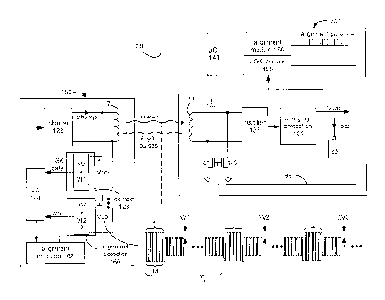
[0032] An improved external charger 150/IPG 200 system having such
functionality is shown schematically in Figure 5. Starting with the IPG 200,
the
basic hardware remains unchanged form the IPG 100 discussed earlier. As
before,
an LSK module 155 monitors the voltage of the battery 26 (Vbat) during
charging,
and when necessary telemeters LSK data back to the external charger, starting
with the issuance of serial data bits on line 99. New to IPG 200 however is an
alignment module 156, which like LSK module 155 also preferably operates as
software in the control circuitry 140. During reception of a magnetic charging
8
CA 02850226 2014-03-26
WO 2013/055526
PCT/US2012/057582
field, the alignment module 156 periodically issues alignment pulses on line
99 to
modulate the impedance of the transistors 141 and 142. As shown, these
alignment pulses can comprise the periodic issuance of a logic '1' pulse
(which
shorts the charging coil 18 to ground) followed by an extended period of no
pulse
(i.e., line 99 is set to '0').
[0033] The timing of the alignment pulses can vary, but in one example the
alignment pulses have a duration (td) of 2 ms and a period (tp) of 200 ms.
Notice
that this relationship between td and tp means that the charging coil 18 is
only
shorted¨and hence unable to receive to power for battery recharging¨for 1% of
the time, which does not significantly extend the time needed to recharge the
battery 26. Both of these timing parameters can be modified over the course of
a
charging session. For example, tp may be relatively short (200 ms) at the
beginning of receipt of a magnetic charging field, when a charging session has
begun and alignment is probably most needed. However, after some number of
seconds suitable to allow for initial alignment adjustment, tp can be
increased
(e.g., to 1 s), which provides alignment data to the external charger less
frequently
but which also disturbs power reception less often.
[0034] Unlike LSK data, the alignment pulses issued by the alignment module
156 are not data per se. They are only meant to occasionally modulate the
impedance of the charging coil 18 for the purpose of creating reflections
assessable at the external charger 150 to infer external charger 150/IPG 200
alignment. It is preferred that the alignment pulses be obviously different
from
the expected structure of LSK data so that they are not misinterpreted at the
external charger 150. For example, if normal LSK data to suspend charging
comprises alternating logic states (01010...) as discussed in the Background,
then
a single alignment pulse followed by a long absence of pulses (effectively,
1000000000...) is not likely to be misinterpreted at the demodulator 123 as
data
for controlling the external charger 150.
[0035] The reflections produced in Vcoil at the external charger 150 by the
alignment pulses are shown in Figure 5. In this example, Vcoil can as before
be
assessed at demodulator 123 to decode LSK telemetry, and to control charging
accordingly. However, Vcoil is additionally assessed in this embodiment at
9
CA 02850226 2014-03-26
WO 2013/055526
PCT/US2012/057582
separate alignment detection circuitry 160. The alignment detection circuitry
160
assesses the magnitude of AV, i.e., the difference in voltage between
reflected ' 1 '
and '0' alignment pulses, and in this embodiment assesses whether this
difference
is greater than a threshold, Vt2. The inventors have noticed that the
magnitude of
AV is indicative of the coupling between the coil 17 in the external charger
and
charging coil 18 in the IPG 200, with AV increasing as coupling improves, and
decreasing as coupling worsens. In the example shown, the alignment detector
160 issues yes/no (e.g., binary) alignment data to the control circuitry 144,
which
in turn controls an alignment indicator 162 similar to that discussed in the
Background: for example, upon hearing, seeing, or feeling (or failing to see,
hear,
or feel) an indication, the user of the external charger 50 can shift the
position of
the external charger 150 until better alignment is achieved, and the
indication
ceases (or issues). The alignment detector 160 can also issue its
determination
directly to the alignment indicator 162, as shown by dotted line in Figure 5.
[0036] The threshold Vt2 used by the alignment detector 160 will generally be
a
threshold significantly higher than Vtl, i.e., the inherent threshold at which
the
demodulator 123 can reliably discern between LSK reception of a '0' or '1'
logic
state. Threshold Vt2 is chosen to guarantee a particular charging rate of the
battery 26 in the IPG 200. Although these thresholds are highly dependent on
the
particular implementation chosen, a Vt2 suitable for use by the alignment
detector
160 may range from 150 mV to 300 mV for example.
[0037] The detector circuitry 160 may be implemented in any number of ways as
one skilled in the art will realize. It may include for example A/D converter
circuitry (not shown) for digitally sampling the Vcoil waveform and for
processing the result to arrive at accurate AV values. Detector circuitry 160
may
average some number of the incoming AV values (AV1, AV2, AV3, etc.) to arrive
at a yes/no determination of alignment that is integrated over time, and is
thus not
as susceptible to "spikes" in the AV data. Alternatively, the digitized values
of
Vcoil can be sent to the control circuitry 144 for interpretation. The
alignment
detector 160 can comprise, or be integrated with, the control circuitry 144,
which
control circuitry 144 can also perform other control functions in the external
charger 150 as one skilled in the art will understand. Moreover, although the
CA 02850226 2014-03-26
WO 2013/055526
PCT/US2012/057582
alignment detector 160 is shown as separate from the demodulator 123 used to
discern LSK data, these two circuits blocks can be integrated, at least in
part. For
example, both the demodulator 123 and the alignment detector 160 can share
front
end A/D converter circuitry used to sample the Vcoil waveform.
[0038] Figure 6 illustrates bench test data showing how Vt2 can be chosen for
use
in the alignment detector 160. In this example, it is assumed that the IPG 200
is
implanted at a depth of 0.5 cm beneath a patient's tissue 25, and is implanted
perfectly flat. Also shown are potential positions for the external charger
150 (in
dotted lines) relative to the IPG 200. A point Z marks the center of the coil
17 in
the external charger, and is used generally to indicate the external charger
150's
position relative to the IPG 200.
[0039] Also shown in Figure 6 are various regions denoting the charging
current
received by the IPG's battery 26, Ibat. Each region reflects the resulting
Ibat
when the external charger 150 is moved so that point Z is located within the
region. As would be expected, this empirical data shows that Ibat is highest
when
point Z (i.e., the external charger 150) is close and centered relative to the
IPG
200, as can be seen in the inner most region where Ibat>65mA. As point Z
becomes more distant, or laterally shifts, coupling worsens, and That begins
to
drop.
[0040] Even though an IPG 200 is usually implanted at a set depth in the
patient's
tissue 25 (here, 0.5 cm), and even though the external charger 150 is usually
in
contact with that tissue, it is useful to consider in Figure 6 the battery
charging
current regions at other depths to understand charging performance when that
depth varies¨i.e., if the implant depth varies or if the distance between the
charger and the tissue varies.
[0041] Also shown in Figure 6 is a boundary at which AV equals a chosen Vt2.
Although only shown in two dimensions, it will be understood that this
boundary
is three-dimensional, and would be shaped roughly as a hemisphere. The shaded
volume within the boundary shows where AV>Vt2, which defines a volume
within which the external charger 150 and IPG 200 will be deemed in alignment
by the alignment detector 160. Notice from the various regions within this
volume that the battery charging current, Ibat ¨> 30mA, i.e., a suitably high
11
CA 02850226 2014-03-26
WO 2013/055526
PCT/US2012/057582
current resulting in a suitably short changing session time. Should an even
higher
That be desired (i.e., even faster charging), an even higher Vt2 could be
chosen for
use in the alignment detector 160, although this would reduce the volume
within
which good alignment would be indicated.
[0042] Returning again to Figure 5, once Vt2 has been set, it is applied at
the
alignment detector 160 to determine whether AV is higher than Vt2, and to
issue a
yes/no decision to the external charger 150's control circuitry 144. Assume an
application in which the external charger issues a "beep" when the external
charger 150 and IPG 200 are not aligned. If some AVx value is <Vt2, indicating
poor coupling, the control circuitry 144 will enable the alignment indicator
162 to
issue a "beep"¨an alignment condition This will provide notice to the user to
laterally move the external charger 150 until the beeping ceases, i.e., until
some
subsequent AVx value is >Vt2. When AVx>Vt2, indicating good alignment, the
control circuitry 144 will not enable the alignment indicator 162, and the
external
charger 150 will be silent- a no-alignment condition.
[0043] While bench test data is useful in setting Vt2 for the alignment
detector
160, it should be understood that Vt2 may need to be programmed into the
external charger 150 for each patient because of the particulars of each
patient's
IPG 200. For example, it cannot be assumed in an actual patient that the
patient's
IPG 200 has been implanted perfectly flat at a depth of 0.5 cm, as was assumed
in
Figure 6. Instead, Vt2 may need to be tailored for each patient on the basis
of
experimentation. In patients having very deep implants, Vt2 may need to be set
at
a relatively small value, but still large enough to provide a reasonable large
volume of alignment. Vt2 can also be set based on simulations or calculations.
Although not shown, it should be understood that Vt2 could be experimentally
determined, and programmed into the external charger 150, in any number of
ways.
[0044] Figures 7 and 8 illustrate a modification to the external charger
150/IPG
200 system of Figures 5 and 6. In this case, the alignment volume is further
refined by considering both AV and Vcoil thresholds at the alignment detector
160. The rationale for this modification is illustrated in Figure 8. Consider
points
A and B at a AV boundary (AVa), i.e., where AVa equals an appropriately
12
CA 02850226 2014-03-26
WO 2013/055526
PCT/US2012/057582
determined Vt2 as explained earlier. Notice that at a point A, which is
centered
with the IPG's axis, provides a battery charging current is relatively high
(That-40mA), while at lateral point B it is relatively low (That-30mA). It is
clear
from the various Ibat regions that such lateral regions proximate to point B
generally define smaller charging current values along a constant AV boundary.
This suggests that while AV can act as an indicator of coupling, it is not a
perfect
one. Thus, using AV as a sole criterion for determining alignment, while
helpful,
does not provide uniform charging at the alignment volume boundary.
[0045] As such, the inventors have noticed that consideration of AV can be
combined with consideration of the actual magnitude of Vcoil at the alignment
detector 160 to further refine the alignment volume to regions of higher
battery
charging currents, Ibat. Of course, Vcoil is an AC varying signal, and so that
signal's magnitude is defined in DC terms in any conventional manner, such as
by
its peak voltage, its peak-to-peak voltage, its rms value, etc.
[0046] A boundary at which Vcoil equals a chosen threshold, Vt4, is
superimposed on two AV boundaries (AVa=Vt2; AVb=Vt3>Vt2) in Figure 8.
Notice that the battery charging current Ibat along this Vcoil boundary is
lower in
regions of poor lateral alignment. (This indicates that Vcoil itself, like AV,
is also
not a perfect indicator of coupling). Unlike AV, which decreases as distance
from
the IPG increases, Vcoil will generally increase as distance from the IPG
increases.
[0047] The shaded volume in Figure 8 shows an improved alignment volume
imposed by more-complicated mathematical conditions, which conditions are
imposed by the alignment detector 160 and/or the control circuitry 144 in this
embodiment to signal alignment. The mathematical conditions are most easily
understood by considering the volume in two parts, each differently shaded in
Figure 8 for easier viewing. The top part indicates an external charger 150
position where AVa>Vt2 and Vcoil>Vt4. (The external charger 150 is not
superimposed in Figure 8 for clarity). The bottom portion indicates an
external
charger 150 position where AVb>Vt3 and Vcoil<Vt4. Satisfaction of either of
these conditions will be interpreted by the control circuitry 144 as an
aligned
condition (hence, the 'or' in the formula in Figure 8).
13
CA 02850226 2014-03-26
WO 2013/055526
PCT/US2012/057582
[0048] Notice that this modified alignment volume excludes notch-shaped lower-
current lateral regions X otherwise included within the volume when only the
AV
threshold is considered (Fig. 6). (Again, in three dimensions this notch X
would
be shaped generally like a ring). Because these regions X provide lower
battery
charging currents, excluding them generally improves the guaranteed battery
charging current to That ¨> 40 mA. Therefore, this modified volume¨arrived at
by considering both AV and Vcoil¨provides for a more refined alignment
volume with faster battery recharge times.
[0049] It should be noticed that this modified volume does not perfectly map
to
higher battery charging currents: there are still small regions inside of the
volume
at the lateral-most points that would provide smaller charging currents (< 40
mA),
and small regions outside of the volume that have suitably high current (> 40
mA). Still, the probability of external charger 150 placement in these regions
is
small compared to the totality of the alignment volume, and such regions are
therefore tolerable. Inclusion of further conditions¨i.e., consideration of
other
AV and Vcoil thresholds¨can be used to further sculpt the alignment volume to
a
more ideal shape having better correlation with the resulting battery charging
currents. Such other even-more-complicated mathematical conditions relying on
pluralities of AV and Vcoil thresholds are not shown for clarity, but should
be
obvious given the basic scheme that is disclosed.
[0050] Circuitry for implementing the alignment scheme of Figure 8 is shown in
Figure 7. The alignment detector in this example can be viewed as having three
separate modules: two for comparing Vcoil to the two AV thresholds (AVa and
AVb), and one for assessing the magnitude of Vcoil. Each is shown as issuing a
yes/no decision to the control circuit 144. It does not particularly matter if
Vcoil
is considered during provision of the alignment pulses (Vcoili) or during
periods
between pulses (Vcoilo): AV is also considered, which relates Vcoilo and
Vcoili,
so either can be used as representative of the magnitude of Vcoil. As before,
it is
not necessary that the circuitry for assessing AVa, AVb and Vcoil be entirely
separate in the alignment detector 160. They can wholly or in part be
combined,
or combined with the demodulator 123 for the LSK data, or combined with the
control circuitry 144. As with the AV thresholds, the Vcoil threshold may be
14
CA 02850226 2014-03-26
WO 2013/055526
PCT/US2012/057582
determined through experimentation, simulation, or calculations and can be
programmed into the external charger 150 by known means.
[0051] Figure 9 illustrates yet another example of an external charger 150 for
use
with the disclosed alignment detection techniques. In this example, the
alignment
detector 160 does not provide yes/no decisions concerning AV (and also
possibly
Vcoil; see Figs. 7 and 8) to the control circuitry 144. Instead, AV (and also
possibly Vcoil) are sent to the control circuitry 144 which processes them,
and
determines alignment in accordance with an alignment algorithm 170. (The
alignment detector 160 in this example could comprise an A/D converter). The
alignment algorithm 170 preferably comprises software accessible by the
control
circuitry 144. In this example, the alignment algorithm 170 is supplied with
coupling information 171 that, generally speaking, relates a coupling
parameter
with AV (and possibly also Vcoil). In the example shown, the information 171
relates the battery charging current Ibat as a function of AV (and possibly
also
Vcoil). Such information may come from families of curves, such as those shown
in Figure 10 as determined by simulation, experimentation, or calculation on
an
actual patient. Again, the information 171 may comprise data stored in a
memory
and associated with the alignment algorithm 170.
[0052] Once the AV (and possibly also Vcoil) data is received from the
alignment
detector 160, the alignment algorithm 170 can call on the information 171 to
make
a determination of the expected coupling between the external charger 150 and
the
IPG 200 at any given moment, e.g., the expected That based on AV (and possibly
also Vcoil). As before, this alignment determination can be indicated to the
patient (162) so that appropriate action (moving the charger) can be taken.
Alternatively, because the alignment algorithm 170 in this example determines
a
relative degree of alignment rather than an alignment/no-alignment
determination,
the alignment indicator 162 may indicate this relative amount to the patient.
For
example, the expect That level as determined by the alignment algorithm 170
may
be displayed to the patient.
[0053] Figure 11 shows another example of an improved external charger 150
relying on the received AV and Vcoil measurements, and the information 171
stored in association with the control circuitry 144. However, in addition to
CA 02850226 2014-03-26
WO 2013/055526
PCT/US2012/057582
indicating mere alignment via alignment indicator 162, alignment quality is
also
indicated to the user via another indicator 163. As will be discussed further
below, such additional indication of alignment quality informs the user
whether to
laterally shift the position of the external charger 150 to achieve even
better
charging performance.
[0054] Alignment quality is illustrated in Figure 12. As one will appreciate
from
the earlier illustrations depicting constant AV and Vcoil boundaries, these
boundaries have different shapes. As such, each AV, Vcoil pair corresponds to
a
particular depth, d, and lateral offset, x of the external charger 150
relative to the
IPG 200. As viewed from the top down in the bottom of Figure 12, any given AV,
Vcoil pair indicates a circle around which the external charger 150 could be
positioned relative to the IPG 200. In other words, each unique AV, Vcoil pair
provides some indication of the relative position of the external charger 150
to the
IPG 200, even if not the exact direction between the two. Two such positions C
and D are shown in Figure 12, each having a unique lateral offset (xc, xD),
but
both at the same depth, dl. Considering positions at the same depth is useful
to
discuss because, as mentioned earlier, the external charger 150 is generally
placed
in contact with the patient's tissue 25 (not shown in Fig. 12), and thus
generally
cannot be changed for a given IPG 200.
[0055] Both positions C and D for the external charger 150 shown in Figure 12
are satisfactorily aligned with the IPG 100, as both are contained with the
alignment volume defined previously in Figure 6 (i.e., AV > Vt2). (The more-
complicated alignment volume of Figure 8 could also be used, but is not
shown).
As such, both positions C and D would trigger alignment indicator 162 (Fig.
11)
as discussed previously. Note however that position C, while aligned, isn't of
the
best alignment quality. It is very near the AV = Vt2 boundary, meaning battery
charging currents could be improved, or that a small change in position could
shift
the external charger out of alignment. Relatively speaking, position C,
although
aligned, can be considered of poor alignment quality. Position D denotes a
shift in
the lateral position from position C, and, by contrast, has a relatively high
battery
charging current and high alignment quality.
16
CA 02850226 2014-03-26
WO 2013/055526
PCT/US2012/057582
[0056] The uniqueness of the position for each AV, Vcoil pair can be used by
the
alignment algorithm 170 to define a high quality alignment volume, shown as
hatched in Figure 12, which boundary occurs at position Q. In the example
shown, the high quality alignment volume defines a volume of constant lateral
offset relative to the axis of the IPG 200¨effectively a cylinder. Although
the
shape of the high quality alignment volume can be changed as will be discussed
further below, a generally cylindrical shape is reasonable when one considers
the
set depth of the IPG 200. When the IPG 200 is implanted relatively shallow
(dl),
and considering the hemispherical shape of the alignment volume, a larger
range
of lateral movement still results in adequate charging. As such, the user has
reasonable leeway to laterally shift the external charger 150 to perhaps
improve
the alignment by shifting towards the high quality alignment volume. By
contrast,
when the IPG 200 is relatively deep (d2) (and assuming that the AV has not
been
adjusted), a smaller amount of lateral shifting is permissible. In such a
case, even
aligned positioned result in minimally-acceptable battery charging currents
values
because all potential aligned values are already close to the alignment
boundary
(AV = Vt2). Therefore, at large depths (d2), most or all aligned positions of
the
external charger 150 may need to be tolerated as high quality alignment
positions,
because the user could not change the quality by lateral shifting in any
event.
[0057] The shape of the high quality alignment volume can be defined and
applied
by the alignment algorithm 170 in conjunction with information 171 (Fig. 11),
which information provides quality boundary values (AVQ, VcoilQ) for each
depth. The quality boundary values are used to define the shape of the high
quality alignment volume, and as mentioned earlier can be set based on
experimentation, calculation, or simulation to provide a particular shape of
that
volume (e.g., cylindrical). The external charger 150 of Figure 11 works as
follows. As the control circuit 144 receives a AV, Vcoil pairs, and in
particular
(AVc, Vcoilc) corresponding to position C, the algorithm 170 would know the
relative position (xc, dl) of the external charger in a circle relative to the
IPG 100.
From that depth, the algorithm can compare (AVc, Vcoilc) to a quality value
(AVQ, VcoilQ) corresponding to that depth, which quality value may be stored
with, or interpretable from, the information 171. In other words, the
algorithm
17
CA 02850226 2014-03-26
WO 2013/055526
PCT/US2012/057582
170 can determine whether position C is within position Q at the boundary of
the
high quality alignment volume. If so, it can trigger the alignment quality
indicator
163; if not, that indicator 163 can remain silent.
[0058] To summarize, both indicators 162 and 163 work together to inform the
user about alignment during the charging process. Alignment indicator 162
indicates whether the external charger 150 is suitably aligned, a condition
indicating that power provided to the implantable medical device is relatively
low.
Alignment quality indicator 163 further indicates the relative quality of that
alignment, and whether it can be improved. For example, if both indicators 162
and 163 are active, the user will know that charging is occurring with high
quality,
because this condition indicates that power provided to the implantable
medical
device is relatively high. If indicator 162 is active but indicator 163 is
not, the
user can know to laterally adjust the position of the external charger 150
until the
indicator 163 activates.
[0059] Note that the user may not know in which relative lateral position to
move
the external charger 150, but finding an improved position is not difficult as
the
user need merely move the charger around to random positions until the
indicator
163 is engaged, in the same way that the user would move the charger to
establish
suitable charging in the first place. Other techniques exist in the art for
indicating
to a user in which direction to move a misaligned external charger to improve
alignment, and such approaches can be used in combination with the disclosed
techniques if necessary. See, e.g., U.S. Patent Publication 2011/0004278.
[0060] The indicators 162 and 163 will preferably provide distinct indications
to
the user so that the user can understand whether the external charger 150 is
suitably aligned but perhaps needing some adjustment, or whether it is well
alignment with good quality and can be left alone. Different tones (high
pitch,
low pitch) could be used. Or, a combined indicator 162/163 can receive the
alignment and alignment quality data to issue an appropriate indication to the
user.
For example, Combined indictor 162/163 might: issue a solid tone when the
external charger 150 is not aligned; issue period beeps when it is aligned but
not
with good quality; and be silent when it is aligned with good quality. If the
external charger 150 is visible to the patient, the indicators 162 and 163 may
18
CA 02850226 2014-03-26
comprise different LEDs on the charger housing, or a single LED 162/163
issuing
different colors or blink rates depending on the relative alignment. Should
the
user interface of the external charger 150 be too simple, or too difficult to
view,
the alignment and quality alignment indications can be sent to another device
external to the charger with a more suitable interface. For example, the
indications can be sent to an external controller for the IPG 200 where they
may
be viewed on the external controller's display, as discussed in U.S. Patent
Publication 2010/09305663.
[0061] Because the alignment quality indicator 163 can be understood as merely
another type of alignment indicator 162, it should be understood that use of
both
types of indictors 162 and 163 in an external charger 150 is not strictly
necessary.
Indeed, the alignment quality indicator 163 can act as the alignment indicator
162
altogether, and can be considered as an alignment indicator.
[0062] To this point in the disclosure, it has been assumed that data-less
periodic
alignment pulses provide the modulation at the IPG 200 to provide the
reflections
at the external charger 150, i.e., the reflections from which AV (and possibly
also
Vcoil) can be assessed according to the disclosed alignment detection
techniques.
However, AV (and Vcoil) can also be gleaned using different constructs. For
example, instead of assessing only alignment pulses, the alignment detector
160
could assess reflections arising from the transmission of actual LSK data,
i.e., data
otherwise intended for decoding at the demodulator 123. This would be a
particularly useful alternative in instances where LSK data is sent from the
IPG
200 with sufficient regularity to also function as a means of detecting
alignment in
accordance with the disclosed techniques. Periodic reporting of the battery
capacity might be one such instance in which both LSK data and alignment data
could be gleaned from the same reflections at the external charger 150.
Moreover,
even if actual LSK data is not used, constructs other than single periodic
alignment pulses could also be used to produce the necessary reflections.
[0063] To this point, it has also been assumed that the coil 17 in the
external
charger 150 is differentially connected to the alignment detector 160, with
both
ends of the coil 17 being received at the alignment detector 160. However,
this is
19
CA 02850226 2014-03-26
WO 2013/055526
PCT/US2012/057582
not strictly necessary. Instead, a single end of the coil 17 can be received
at the
alignment detector 160.
[0064] It has also been assumed that the coil voltage (AV and/or Vcoil) is
assessed
to make the alignment decision, but this is not strictly necessary, and
instead other
electrical parameters of the coil could also be assessed. For example, in
other
embodiments, Vcoil produced by the charging circuitry 122 can be fixed, which
would cause the charging current, Icharge, through the coil 17 to vary as the
impedance of the coil 18 in the IPG 200 is modulated. The technique could
therefore be modified to monitor the current through the coil (AIcharge and/or
Icoil) to make alignment determinations. Moreover, coil electrical parameters
(e.g., voltage or current) could also be processed, scaled, regulated, or
buffered
before being presented to the alignment detector 160. Any of these means of
detection comprises "assessment" of the relevant electrical parameter or its
change.
[0065] It has also been assumed that the magnetic charging field is used to
provide
power to charge the battery 26 in the IPG 200. However, the IPG 200 need not
contain a battery 26, and instead the external charger 150 can be used to
provide
continuous power to operate the IPG 200.
[0066] Finally, the alignment techniques disclosed herein can be used in
conjunction with the above-referenced concurrently-filed application, which
uses
AV (and possibly also Vcoil) to provide closed loop charging of the IPG.
[0067] Although particular embodiments of the present invention have been
shown and described, it should be understood that the above discussion is not
intended to limit the present invention to these embodiments. It will be
obvious to
those skilled in the art that various changes and modifications may be made
without departing from the spirit and scope of the present invention. Thus,
the
present invention is intended to cover alternatives, modifications, and
equivalents
that may fall within the spirit and scope of the present invention as defined
by the
claims.