Note: Descriptions are shown in the official language in which they were submitted.
CA 02850692 2015-11-26
COMMON RAIL FUEL INJECTION SYSTEM
Technical Field
[0001]
The present invention relates to a common rail fuel
injection system for a diesel internal combustion engine,
and more specifically to a common rail fuel injection system
which is used in a diesel internal combustion engine and
accumulates pressurized fuel in a common rail to inject the
same into each cylinder.
Background Art
[0002] A common rail fuel injection system for a diesel
internal combustion engine is a fuel injection system of an
electromagnetic control type which accumulates high-pressure
fuel in a common rail by a high-pressure supply pump to
inject high-pressure fuel accumulated in the common rail
into each cylinder, and a conventional common rail fuel
injection system for a diesel internal combustion engine is
shown in Figure 28.
The structure of the common rail fuel injection system
is provided with an injector provided for each cylinder in a
diesel internal combustion engine, a common rail for
accumulating pressurized fuel to be supplied to the injector,
a high-pressure fuel supply pump which supplies high-
pressure fuel to the common rail, a fuel injection pipe
which causes the common rail and the injector to communicate
with each other, and a fuel supply pipe which causes the
common rail and the high-pressure supply pump to communicate
with each other.
1
CA 02850692 2015-11-26
[0003] In such a common rail fuel injection system, a means
is desired which can suppress pressure fluctuation within
the injector due to fuel injection (pressure drop at an
injection time) by a simple means and can obtain an even
injection pressure characteristic without increasing the
sizes of the common rail and the fuel injection pipe.
[0004] In the conventional art shown in Figure 28, it is
necessary to reduce a pressure drop amount at an injection
time in order to suppress the pressure fluctuation within
the injector due to fuel injection (pressure drop at an
injection time) and obtain the even injection pressure
characteristic. Therefore, it is effective to adopt an
injection pipe with a larger inner diameter. On the other
hand, though further pressure increase in the common rail
system is also required in the future in order to suppress
exhaust of smoke, when the inner diameter of the injection
pipe is enlarged, it is necessary to improve inner-pressure
fatigue strength performance, so that it is necessary to
make a pipe strength higher than an existing material.
Therefore, it is required to carefully select a fuel pipe
material and adopt an expensive manufacturing process, so
that rising of a manufacturing cost becomes essential.
[0005] The present applicant has proposed a technique shown
in Patent Literature 1 to such a problem. A representative
example of the technique is shown in Figure 29.
In Patent Literaturel, as shown in Figure 29, internal
volumes of a common rail 22, fuel injection pipes 23 and
injectors 21 are secured by connecting injectors 21
positioned adjacent to each other by a pipe 26 to cause
inside of the pipe 26 to function as a sub-pressure
accumulation chamber and providing another connection
portion different from a connection portion with a fuel
2
CA 02850692 2015-11-26
injection pipe 23 within a high-pressure flow path for
introducing high-pressure fuel from a common rail 22 into
the injector 21 via the fuel injection pipe 23 or within a
high-pressure flow path inside the injector 21 to which
pressure fluctuation due to fuel injection is transmitted as
a means for connecting the injectors 21 adjacent to each
other by the pipe 26, and connecting the pipe 26 to the
another connection portion to perform connection with the
same connection portions of the injectors of cylinders
adjacent to each other, so that a fuel injection system
having a good responsiveness and an accurate injection
characteristics is obtained by enhancing responsiveness of
fuel injection (follow-up performance to an instruction
signal from a vehicle-mounted CPU) and preventing pressure
drop within the injector due to fuel injection without
enlarging the inner diameters of the common rail and the
fuel injection pipe or increasing the lengths thereof.
[0006] Further, in Figure 10 of Patent Literature 2,
injection valves 2 are arranged corresponding to combustion
chambers of respective cylinders of an engine, and fuel is
injected to the combustion chambers of the respective
cylinders in the determined order of the cylinders, for
example, in the order of cylinders #1, #3, #4, and #2
according to ON and Off of injection-control solenoid valves
3. These injection valves 2 are connected to a common rail
common to the respective cylinders via branch supply pipes
4 having a first fuel passage 14 shown in Figure 1. Further,
high-pressure fuel is accumulated up to a predetermined
pressure in a pressure accumulation chamber 15 formed in the
common rail 5, and the high-pressure fuel accumulated in the
pressure accumulation chamber 15 is injected into the
combustion chambers of the respective cylinders of the
3
CA 02850692 2015-11-26
engine 1 from the injection valves 2 via the branch supply
pipes 4 during openings of the solenoid valves 3. Further,
the branch supply pipes 4 adjacent to each other are
connected by a coupling pipe 61, 62, or 63 as pulsation
reducing machine, so that rigidity of the branch supply
pipes 4 are enhanced.
Therefore, a fuel injection device which can reduce
vibration amplitudes of the branch supply pipes 4 serving as
thin pipes has been proposed.
[0007] Further, a accumulator type fuel injection device
proposed on Figure 2 of Patent Literature 3 is configured to
pool fuel pressurized by a high-pressure fuel pump 1 in a
high-pressure accumulator 3 communicating with a fuel
passage 10a and common to respective cylinders, but, for
example, selector valves (first control valves) 5 for fuel
injection rate switching composed of a two-directional
solenoid valve are provided for respective cylinders in the
halfway of the fuel passage 10a, and check valves 32 which
allow only flow of fuel from an upstream side to a
downstream side are provided just downstream of the selector
valves 5. Further, a low-pressure accumulator (second
pressure accumulator) 4 common to the respective cylinders
is connected to the fuel passage 10a via fuel passages 10b
branched from the fuel passage 10a downstream of the check
valves 32.
Further, a check valve 6 and a bypass passage for
bypassing the check valve 6 are provided in the branched
fuel passage 10b, and an orifice 6a is provided in the
bypass passage. The check valve 6 allows only flow of fuel
from the low-pressure accumulator 4 in the direction of the
fuel passage 10a.
4
CA 02850692 2015-11-26
That is, when the fuel pressure in the fuel passage
10a is higher than the fuel pressure in the branched fuel
passage 10b, fuel within the fuel passage 10a flows in the
branched fuel passage 10b via the orifice 6a and further
flows into the low-pressure accumulator 4, thereby
suppressing fluctuation of the fuel pressure.
[0008] In such conventional arts as proposed in Patent
Literatures 1, 2 and 3, it is possible to suppress pressure
fluctuation within an injector due to fuel injection and
obtain an even injection pressure characteristic by
increasing a pressure accumulation volume, but there is such
a drawback that a structure for achieving such an effect is
complicated, which results in increase in device weight.
Citation List
Patent Literature
[0009] PTL 1: Japanese Patent Application Laid-Open No.
2007-182792 (see Figure 2)
PTL 2: Japanese Patent Application Laid-Open No. H10-
30521 (see Figure 10)
PTL 3: Japanese Patent Application Laid-Open No. 2000-
161171 (see Figure 2)
Summary of Invention
Technical Problem
[0010] In view of these circumstances, an object of the
present invention is to provide a common rail fuel injection
system which, by a simple means, can suppress pressure
fluctuation within an injector due to fuel injection, can
obtain an even fuel injection pressure characteristic and
can reduce harmful exhaust gas from a diesel internal
CA 02850692 2015-11-26
combustion engine, without enlarging the sizes of a common
rail and a fuel injection pipe.
Solution to Problems
[0011] A first aspect of the present invention is a common
rail fuel injection system including injectors having a fuel
intake port and being provided in respective cylinders of a
multi-cylinder diesel internal combustion engine; a common
rail accumulating pressurized fuel supplied to the
injectors; a high-pressure supply pump supplying high-
pressure fuel to the common rail; a fuel supply pipe causing
the common rail and the high-pressure supply pump to
communicate with each other; and fuel injection pipes
communicating with pressure supply ports provided in the
common rail and causing the injectors and the pressure
supply ports provided in the common rail to communicate with
each other, wherein the fuel injection pipes communicate
with at least three injectors in series, the number Np of
pressure supply ports provided in the common rail is less
than the number NI of injectors, and supply of high-pressure
fuel to the respective injectors for the cylinders is
performed through the fuel injection pipes of two lines.
[0012] A second aspect of the present invention is the
common rail fuel injection system according to the first
aspect, where the multi-cylinder diesel internal combustion
engine is a diesel internal combustion engine having at
least three cylinders.
[0013] A third aspect of the present invention is the common
rail fuel injection system according to the first or second
aspect, where the multi-cylinder diesel internal combustion
engine is a diesel internal combustion engine having at
least three injectors.
6
CA 02850692 2015-11-26
[0014] A fourth aspect of the present invention is the
common rail fuel injection system according to any one of
the first to third aspects, where a relationship between the
number of pressure supply ports provided in the common rail
and the number of injectors is set such that the number of
twice the number obtained by dividing the number NI of
injectors by an aliquot which is three or more in aliquots
of the number NI of injectors coincides with the number Np
of pressure supply ports as shown in the following Equation
(1).
[0015]
Np ¨ 2 x {Ni/(an aliquot which is three of more in
aliquots of NI) }¨ (1)
Advantageous Effects of Invention
[0016] According to the present invention, it is made
possible to reduce an exhaust amount of smoke as compared
with the conventional structure by suppressing pressure
pulsation generated due to injection and reducing an
pressure drop amount at an injection time to improve an
average value of pressures during injection (hereinafter,
referred to as "average injection pressure value).
Further, since reduction of a peak pressure acting on
the injection pipe can be made possible, the reduction is
advantageous regarding an internal pressure fatigue strength
performance of the injection pipe, a set pressure to the
common rail system can be raised, and an exhaust amount of
smoke can be suppressed.
In addition, since the average injection pressure
value can be increased, it is unnecessary to elevate the
injection pressure of the common rail system itself beyond
necessity so that size reduction of the common rail system
7
CA 02850692 2015-11-26
(the pump, the common rail, and the injector) can be
achieved.
Furthermore, an improvement effect of fuel consumption
can also be obtained according to the above operation.
Brief Description of Drawings
[0017] Figure 1 is a schematic view for explaining a fuel
injection system of the present invention;
Figure 2A is a diagram showing pressure change within
a fuel injection pipe at a fuel injection time and showing
an operating state of an injection needle valve at a
rotational angle of a crank shaft.
Figure 2B is a diagram showing pressure change within
a fuel injection pipe at a fuel injection time and showing a
pressure change within the fuel injection pipe in the state
shown in Figure 2A;
Figure 3 is a diagram showing average pressures within
the fuel injection pipe before and after fuel injection and
during fuel injection;
Figure 4 is a diagram showing an exhaust amount of
smoke in a real machine of an engine;
Figure 5 is a diagram showing a fuel consumption
according to BSFC index;
Figure 6 is a diagram showing a value obtained by
dividing an average pressure within an injection pipe by a
whole volume of a fuel injection system, namely, an average
pressure within an injection pipe per unit volume of a fuel
injection system;
Figure 7 is a schematic view for explaining a fuel
injection system according to Example 1;
Figure 8 is a schematic view for explaining a fuel
injection system according to Example 2;
8
CA 02850692 2015-11-26
Figure 9 is a schematic view for explaining a fuel
injection system according to Example 3;
Figure 10 is a schematic view for explaining a fuel
injection system according to Example 4;
Figure 11 is a schematic view for explaining a fuel
injection system according to Example 5;
Figure 12 is a schematic view for explaining a fuel
injection system according to Example 6;
Figure 13 is a schematic view for explaining a fuel
injection system according to Example 7;
Figure 14 is a schematic view for explaining a fuel
injection system according to Example 8;
Figure 15 is a schematic view for explaining a fuel
injection system according to Example 9;
Figure 16 is a schematic view for explaining a fuel
injection system according to Example 10;
Figure 17 is a schematic view for explaining a fuel
injection system according to Example 11;
Figure 18 is a schematic view for explaining a fuel
injection system according to Example 12;
Figure 19 is a schematic view for explaining a fuel
injection system according to Example 13;
Figure 20 is a schematic view for explaining a fuel
injection system according to Example 14;
Figure 21 is a schematic view for explaining a fuel
injection system according to Example 15;
Figure 22 is a schematic view for explaining a fuel
injection system according to Example 16;
Figure 23 is a schematic view for explaining a fuel
injection system according to Example 17;
Figure 24 is a schematic view for explaining a fuel
injection system according to Example 18;
9
CA 02850692 2015-11-26
Figure 25 is a schematic view for explaining a fuel
injection system according to Example 19;
Figure 26 is a schematic view for explaining a fuel
injection system according to Example 20;
Figure 27 is a schematic view for explaining a fuel
injection system according to Example 21;
Figure 28 is a schematic view of a fuel injection
system according to a conventional example; and
Figure 29 is a schematic view of a fuel injection
system shown in Patent Literature 1 (Figure 2).
Description of Embodiments
[0018] Figure 1 is a schematic view for explaining a fuel
injection system of the present invention, which corresponds
to a 6-cylinder diesel internal combustion engine.
In Figure 1, reference sign 1 denotes an injector; 2
denotes a common rail; 2a, 2b denotes a pressure supply
port;, 3 denotes a fuel injection pipe; 3a, 3b denotes a
fuel injection pipe communicating with each of the pressure
supply ports 2a and 2b of the common rail; 4 denotes a
coupling connector; 5 denotes a connection nut; 11 denotes a
fuel injection pipe; 12 denotes a high-pressure supply pump;
and 10 denotes a fuel injection system of the present
invention.
A case where the number Np of pressure supply ports is
two, the number NI of injectors 1 is six, and the number of
twice the number obtained by performing division by 6 which
is an aliquot which is three or more in aliquots of the
number NT is the number Np of pressure supply ports is shown.
Here, the fuel injection pipes 3a and 3b communicate
with the pressure supply ports 2a and 2b of the common rail
CA 02850692 2015-11-26
2, respectively, and they are for supplying high-pressure
fuel to the fuel injection pipes 3 communicating with six
injectors 1 in a series.
[0019] Further, summarizing the relationship between the
number Np of pressure supply ports and the number NI of
injectors 1, a relationship shown by the following Equation
(2) is obtained, and the relationship in an actual multi-
cylinder diesel internal combustion engine (three cylinders
to eight cylinders) is shown in Table 1. The relationship
of Equation (2) can also be applied to even a diesel
internal combustion engine having further more cylinders.
[0020] Equation (2)
Np = 2 X {N1/(an aliquot which is three or more in
aliquots of NI)} (2)
[0021] Table 1
The number The number The number Example
of of of
cylinders injectors pressure
supply No. Reference
ports in Figure
common
rail Np
three three two points Examples 7 Figure 13
cylinders to 9 to Figure
15
four four two points Examples Figure 16
cylinders 10 to 12 to Figure
18
fifth five two points Examples Figure 19
cylinders 13 to 15 to Figure
21
six six two points Examples 1 Figure 7
cylinders to 3 to Figure
9
four Examples
4 Figure 10
points to 6 to Figure
12
eight eight two points Examples Figure 22
cylinders 16 to 18 to Figure
24
CA 02850692 2015-11-26
four Examples Figure 25
points 19 to 21 to Figure
27
[0022] In Figure 1, high-pressure fuel is supplied to each
injector 1 in such an aspect that fuels fed from two lines
of a fuel supply line A extending through the fuel injection
pipe 3a and fed from a fuel supply line B extending through
the fuel injection pipe 3b are mixed at each coupling
connector 4 before fuel intake into the injector 1, for
example, as shown in Fig. 1.
By supplying fuels from the two lines, namely from two
directions in this manner, fuel pressure after mixing
becomes an average pressure of the two lines so that
pressure fluctuation (pulsation) is relaxed.
[0023] How to mix fuels supplied from routes of the two
lines must be performed before fuel injection into cylinders,
as shown in the fuel injection system of Figure 1.
Therefore, a method for performing coupling and mixing
simultaneously using parts such as the coupling connectors 4
for coupling fuel routes, a method for performing mixing of
fuels in an injector by providing two fuel intake ports in
an injector and causing fuel injection pipes of respective
fuel routes to communicate with the respective fuel intake
ports, or the like is proposed.
[0024] Additionally, in explanation using Figure 1, the case
where the number Np of pressure supply ports provided in the
common rail is an even number corresponding to one set of
two ports is described, but when the number of pressure
supply ports is an odd number, for example, the pressure
supply ports may be provided as one set of three ports.
EXAMPLE
12
CA 02850692 2015-11-26
[0025] The present invention will be further described below
using Examples.
<Example 1>
[0026] Figure 7 is a schematic view of a fuel injection
system 10a according to Example 1 (a case where same devices
such as the fuel supply pipe and the high-pressure supply
pump are used is not shown in the figures described below).
In Figure 7, reference sign 1 denotes an injector; 2
denotes a common rail; 2a, 2b denotes a pressure supply port
provided in the common rail 2; 3, 3a, 3b denotes a fuel
injection pipe; 4 denotes a coupling connector; and 5
denotes a connection nut.
[0027] The fuel injection system 10a of Example 1 is one for
a 6-cylinder diesel internal combustion engine, which has
six injectors 1 (NI = 6) and supplies high-pressure fuels to
the six injectors 1 connected in series from the pressure
supply ports 2a and 2b provided in the common rail 2 having
two ports {(Np = 2 x (6/6))I through the fuel injection
pipes 3a and 3b communicating with the pressure supply ports
2a and 2b, respectively.
In the fuel injection system 10a of Example 1, supply
of fuel to each injector 1 is performed such that fuels are
fed to a coupling connector 4 from two directions of the
fuel supply line A where fuel is fed through the pressure
supply port 2a and the fuel injection pipe 3a and the fuel
supply line B where fuel is fed through the pressure supply
port 2b and the fuel injection pipe 3b, and after pressures
of the fuels are averaged in the coupling connector 4, the
fuels are fed to an injector 1 coupled to the coupling
connector 4 by a connection nut 5 to be injected into a
corresponding cylinder.
13
CA 02850692 2015-11-26
[0028] (Conventional example)
As the conventional example, the fuel injection system
shown in Figure 28 was used.
In Figure 28, reference sign 20A denotes a fuel
injection system of the conventional example; 21 denotes an
injector; 22 denotes a common rail; and 23 denotes a fuel
injection pipe, but the fuel supply pipe, the high-pressure
supply pump and the like are not shown.
The fuel injection system 20A shown in Figure 28 is a
fuel injection system corresponding to a 6-cylinder diesel
internal combustion engine like Example 1, where six fuel
injection pipes 23 individually communicating with
respective six injectors 21 from the common rail 22 to
supply high-pressure fuel to the six injectors 21
communicate with six pressure supply ports of the common
rail.
[0029] [Performance comparison of the fuel injection system
with the present invention]
Pressure fluctuation within the injection pipe at fuel
injection time, behaviors of exhaust gases and fuel
consumption behaviors were measured using the fuel injection
systems of Example 1 (the fuel injection system 10a shown in
Figure 7) and the conventional example (the fuel injection
system 20A shown in Figure 28).
The result will be explained with reference to Figure
2 to Figure 6.
[0030] In Figures 2A and 2B, Crank Angle of an engine is
plotted along a horizontal axis, and an operation amount of
an injector needle valve is plotted along a vertical axis in
Figure 2A, while an injection pipe internal pressure is
plotted along a vertical axis in Figure 2B. Where lift-up
was performed at a certain angle, the conventional example
14
CA 02850692 2015-11-26
(the fuel injection system 20A shown in Figure 28) and
Example 1 (the fuel injection system 10a shown in Figure 7)
were compared with each other.
It is understood that in the conventional example
receiving fuel supply from one direction, large pressure
drop and pressure fluctuation occur due to the lift, but in
the present invention Example receiving fuel supply from two
directions, since fuel supply is promoted, pressure drop and
pressure fluctuation can be suppressed.
[0031] Figure 3 is a diagram showing average pressures
within the injection pipe before and after fuel injection
and during fuel injection, where the fuel injection systems
of the conventional example and Example 1 are compared with
each other.
A combustion efficiency is generally enhanced by
obtaining a high average injection pressure, so that
reduction of an exhaust amount of smoke and improvement of
the fuel consumption can be obtained.
From Figure 3, it is understood that the average
injection pressure is 95% of a pressure before injection in
the conventional example, while a high pressure up to 98%
can be obtained in the present invention example.
[0032] Figure 4 is a diagram where comparison about a
relationship between an exhaust amount of NOx and an exhaust
amount of smoke in an real machine of the internal
combustion engine is performed between the conventional
example and Example 1 of the present invention , from which
it is understood that the exhaust amount of smoke in
combustion where occurrence of NOx is suppressed is reduced
by 15% in Example 1 of the present invention as compared
with the conventional example, and occurrence of NOx is
suppressed in Example 1 of the present invention when
CA 02850692 2015-11-26
comparison is performed regarding the same exhaust amount of
smoke between the conventional example and Example 1 of the
present invention.
[0033] Further, Figure 5 is a diagram showing a relationship
between a fuel consumption based upon BSFC (Break Specific
Fuel Consumption) index and an exhaust amount of NOx, which
shows that the fuel consumption is improved by about 2% in
Example 1 of the present invention example under a
combustion condition where the same amount of NOx is
exhausted in the conventional example and Example 1 of the
present invention example.
[0034] From the results shown in Figure 3 to Figure 5, since
the fuel injection system according to the present invention
suppresses pressure pulsation generated due to fuel
injection as compared with the fuel injection system having
the conventional structure to make reduction of a peak
pressure acting on the fuel injection pipe possible, a set
pressure of the common rail system (the high-pressure supply
pump, the common rail, and the injector) can be raised,
which shows a large effect on suppression of an exhaust
amount of smoke.
Furthermore, since it is also possible to raise an
injection pressure during injection, it is unnecessary to
raise the injection pressure of the common rail system
itself beyond necessity, so that size reduction of the
common rail system (the pump, the rail, and the injector)
can be achieved.
[0035] Next, comparison was performed regarding a value
obtained by dividing an average pressure within an injection
pipe by a whole volume of the fuel injection system (namely,
an average injection pressure value within the injection
pipe per unit volume of the fuel injection system) in order
16
CA 02850692 2015-11-26
to fairly evaluate the fuel injection systems of the
conventional examples shown in Patent Literatures 1 to 3 and
an effect of an added volume in the fuel injection system of
the present invention example of Example 1 to the average
injection pressure correlated with an exhaust gas
performance. The result of the comparison is shown in
Figure 6.
The present invention example shows a high value to
the respective conventional examples and the fuel injection
system according to the present invention is also superior
in exhaust gas performance to the respective conventional
examples.
<Example 2>
[0036] A schematic view of a fuel injection system 10b
according to Example 2 is shown in Figure 8.
The fuel injection system 10b of Example 2 is one for
the same 6-cylinder diesel internal combustion engine as
that of Example 1, Example 2 being the same as Example 1
such that the number NI of injectors 1 provided is also six,
the number Np of pressure supply ports provided in the
common rail 2 is also two (2a and 2b), and fuel where
pressures in the fuel supply routes A and B of two lines
have been averaged via each of coupling connectors 4 is
supplied to a corresponding injector 1 to be injected into a
corresponding cylinder.
[0037] A difference from Example 1 lies in a point that fuel
is fed from each coupling connector 4 to a corresponding
injector 1 via a fuel injection pipe 3. By feeding fuel via
the fuel injection pipe 3, such a merit can be provided that
the degree of freedom of arrangement of the fuel injection
system within the engine room is increased.
<Example 3>
17
CA 02850692 2015-11-26
[0038] A schematic view of a fuel injection system 10c
according to Example 3 is shown in Figure 9.
The fuel injection system 10c of Example 3 is one for
the same 6-cylinder diesel internal combustion engine as
those of Examples 1 and 2, Example 3 being the same as
Examples 1 and 2 such that the number NI of injectors 1
provided is also six and the number Np of pressure supply
ports provided in the common rail 2 is also two (2a and 2b),
but it is a fuel injection system of a type where fuels from
fuel supply routes A and B of two lines are directly fed to
two fuel intake ports 6 and 6 provided in each injector 1
without interposition of any coupling connector as in
Examples 1 and 2, averaging of fuel pressures within an
injector 1 is performed, and injection into a corresponding
cylinder is then performed.
<Example 4>
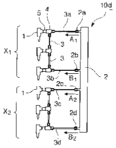
[0039] A schematic view of a fuel injection system according
to Example 4 is shown in Figure 10.
The fuel injection system 10d of Example 4 is one for
the same 6-cylinder diesel internal combustion engine as
those of Examples 1 to 3, which has 6 injectors 1 (NI = 6)
and has pressure supply ports 2a, 2b, 2c and 2d provided in
the common rail 2 having four ports {(Np - 2 x (6/3)), and
supplies high-pressure fuel to three injectors 1 (x1 group)
connected in series through the pressure supply ports 2a and
2b and the fuel injection pipes 3a and 3b communicating
therewith, respectively and further supplies high-pressure
fuel to three injectors 1 (x2 group) connected in series via
the pressure supply ports 2c and 2d and the fuel injection
pipes 3c and 3d communicating therewith, respectively.
[0040] In the fuel injection system 10d of Example 4, supply
of fuel to each injector 1 is performed regarding the xl
18
CA 02850692 2015-11-26
group and the x2 group which include three injectors
according to division, respectively, such that: regarding
the xl group, fuels are fed to a coupling connector 4 from
two directions of a fuel supply line Al where fuel flows
through the pressure supply port 2a and the fuel injection
pipe 3a and a fuel supply line Bl where fuel flows through
the pressure supply port 2b and the fuel injection pipe 3b,
and after pressures of the fuels are averaged in the
coupling connector 4, the fuels are supplied to an injector
1 coupled to the coupling connector 4 by a connection nut 5
to be injected into a targeted cylinder; and regarding the
group x2 composed of the other three injectors, fuels are
fed to a coupling connector 4 from two directions of a fuel
supply line A2 where fuel flows through the pressure supply
port 2c and the fuel injection pipe 3c and a fuel supply
line B2 where fuel flows through the pressure supply port 2d
and the fuel injection pipe 3d, and after pressures of the
fuels are averaged in the coupling connector 4, the fuels
are supplied to an injector 1 coupled to the coupling
connector 4 by a connection nut 5 to be injected into a
targeted cylinder.
As for the injector 1, an injector of a type similar
to that in Example 1 is used.
[0041] In Example 4, since the number of injectors to which
fuel is supplied is three which is a half of the number of
injectors in Examples 1 to 3, the stroke of fuel is short,
which has an advantage for pressure fluctuation in the fuel
injection pipe.
<Example 5>
[0042] A schematic view of a fuel injection system according
to Example 5 is shown in Figure 11.
19
CA 02850692 2015-11-26
A fuel injection system 10e of Example 5 is a fuel
injection system of a type similar to that in Example 4.This
system 10e is one for the 6-cyliner diesel internal
combustion engine as those of Examples 1 to 3, which has six
injectors 1 (NI = 6) and has pressure supply ports 2a, 2b,
2c, and 2d provided in a common rail 2 having four ports
{(Np = 2 x (6/3))}, and supplies high-pressure fuel to three
injectors (the xl group) connected in series through the
pressure supply ports 2a and 2b and the fuel injection pipes
3a and 3b communicating therewith, respectively, and further
supplies high-pressure fuel to three injectors (the x2
group) connected in series through the pressure supply ports
2c and 2d and the fuel injection pipes 3c and 3d
communicating therewith, respectively.
[0043] In the fuel injection system 10e of Example 5, supply
of fuel to each injector 1 is performed regarding a xl group
and a x2 group which include three injectors according to
division, respectively, such that: regarding the xl group,
fuels are fed to a coupling connector 4 from two directions
of a fuel supply line Al where fuel flows through the
pressure supply port 2a and the fuel injection pipe 3a and a
fuel supply line Bl where fuel flows through the pressure
supply port 2b and the fuel injection pipe 3b, and after
pressures of the fuels are averaged in the coupling
connector 4, the fuels are supplied to an injector 1 coupled
to the coupling connector 4 by a fuel injection pipe 3 to be
injected into a targeted cylinder; and regarding the group
x2 composed of the other three injectors, fuels are fed to a
coupling connector 4 from two directions of a fuel supply
line A2 where fuel flows through the pressure supply port 2c
and the fuel injection pipe 3c and a fuel supply line B2
where fuel flows through the pressure supply port 2d and the
CA 02850692 2015-11-26
fuel injection pipe 3d, and after pressures of the fuels are
averaged in the coupling connector 4, the fuels are supplied
to an injector 1 coupled to the coupling connector 4 by a
fuel injection pipe 3 to be injected into a targeted
cylinder.
As for the injector 1, an injector of a type similar
to that in Example 2 is used.
[0044] In Example 5, since the number of injectors to which
fuel is supplied is three which is a half of the number of
injectors in Examples 1 to 3, the stroke of fuel is short,
which has an advantage for pressure fluctuation in the fuel
injection pipe.
The fuel injection system 10e of Example 5 is
different from the fuel injection system 10d of Example 4 in
that the injector 1 is connected to the coupling connector 4
through the fuel injection pipe 3 in the former.
<Example 6>
[0045] A schematic view of a fuel injection system according
to Example 6 is shown in Figure 12.
The fuel injection system 10f of Example 6 is a fuel
injection system of a type similar to that in Example 4.
This system 10f is also one for the 6-cyliner diesel
internal combustion chamber as those of Examples 1 to 5,
which has six injectors 1 (NI = 6) and has pressure supply
ports 2a, 2b, 2c, and 2d provided in a common rail 2 having
four ports {(Np - 2 x (6/3))I, and supplies high-pressure
fuel to three injectors (the xl group) connected in series
through the pressure supply ports 2a and 2b and the fuel
injection pipes 3a and 3b communicating therewith,
respectively, and further supplies high-pressure fuel to
three injectors (the x2 group) connected in series through
21
CA 02850692 2015-11-26
the pressure supply ports 2c and 2d and the fuel injection
pipes 3c and 3d communicating therewith, respectively.
It is to be noted that the injectors 1 used in Example
6 have a type similar to those of Example 3, has and each
injector has two fuel intake ports 6 and performs averaging
of fuel pressures within the injector.
[0046] In the fuel injector system 10f of Example 6, like
the case of Examples 4 and 5, supply of fuel to each
injector 1 is performed regarding a group xl and a group x2
including three injectors according to division,
respectively, such that: regarding the xl group, fuels are
fed to two fuel intake ports 6 provided on an injector 1
from two directions of a fuel supply line Al where fuel
flows through the pressure supply port 2a and the fuel
injection pipe 3a and a fuel supply line B1 where fuel flows
through the pressure supply port 2b and the fuel injection
pipe 3b, and after pressures of the fuels are averaged
within the injector 1, the fuels are injected into a
targeted cylinder; and regarding the x2 group composed of
the other three injectors, fuels are fed to two fuel intake
ports 6 provided on an injector 1 from two directions of a
fuel supply line A2 where fuel flows through the pressure
supply port 2c and the fuel injection pipe 3c and a fuel
supply line B2 where fuel flows through the pressure supply
port 2d and the fuel injection pipe 3d, and after pressures
of the fuels are averaged within the injector 1, the fuels
are injected into a targeted cylinder.
[0047] In Example 6, since the number of injectors to which
fuel is supplied is three which is a half of the number of
injectors in Examples 1 to 3, the stroke of fuel is short,
which has an advantage for pressure fluctuation in the fuel
injection pipe.
22
CA 02850692 2015-11-26
The fuel injection system 10f is different from the
fuel injection systems 10d and 10e of Examples 4 and 5 in
that the averaging of fuel pressure is performed within the
injector 1 in the fuel injection system 10f.
<Example 7>
[0048] A schematic view of a fuel injection system according
to Example 7 is shown in Figure 13.
The fuel injection system lOg of Example 7 is one for
a 3-cylinder diesel internal combustion engine, which has
three injectors 1 (NI = 3), and supplies high-pressure fuel
to three injectors connected in series from the pressure
supply ports 2a and 2b provided in the common rail 2 having
two ports {(Np = 2 x (3/3))1 through the fuel injection
pipes 3a and 3b communicating with the pressure supply ports
2a and 2b, respectively.
[0049] In the fuel injection system lOg of Example 7, supply
of fuel to each injector 1 is performed such that fuels are
fed to a coupling connector 4 from two directions of a fuel
supply line A where fuel flows through the pressure supply
port 2a and the fuel injection pipe 3a and a fuel supply
line B where fuel flows through the pressure supply port 2b
and the fuel injection pipe 3b, and after pressures of the
fuels are averaged in the coupling connector 4, the fuels
are supplied to an injector 1 coupled to the coupling
connector 4 by a connection nut 5 to be injected to a
corresponding cylinder.
Example 8
[0050] A schematic view of a fuel injection system according
to Example 8 is shown in Figure 14.
The fuel injection system 10h of Example 8 is a fuel
injection system of a type similar to that in Example 7.
23
CA 02850692 2015-11-26
The fuel injection system 10h of Example 8 is one for
a 3-cylinder diesel internal combustion engine, which has
three injectors 1 (NI - 3), and supplies high-pressure fuel
to three injectors connected in series from the pressure
supply ports 2a and 2b provided in the common rail 2 having
two ports {(Np = 2 x (3/3))I through the fuel injection
pipes 3a and 3b communicating with the pressure supply ports
2a and 2b, respectively.
[0051] In the fuel injection system 10h, supply of fuel to
each injector 1 is performed such that fuels are fed to a
coupling connector 4 from two directions of a fuel supply
line A where fuel flows through the pressure supply port 2a
and the fuel injection pipe 3a and a fuel supply line B
where fuel flows through the pressure supply port 2b and the
fuel injection pipe 3b, and after pressures of the fuels are
averaged in the coupling connector 4, the fuels are supplied
to an injector 1 coupled to the coupling connector 4 by a
fuel injection pipe 3 to be injected to a corresponding
cylinder.
<Example 9>
[0052] A schematic view of a fuel injection system according
to Example 9 is shown in Figure 15.
A fuel injection system 10i of Example 9 is a fuel
injection system of a type similar to those in Examples 7
and 8.
The fuel injection system 10i of Example 9 is one for
a 3-cylinder diesel internal combustion engine, which has
three injectors 1 (NI = 3), and supplies high-pressure fuel
to three injectors connected in series from the pressure
supply ports 2a and 2b provided in the common rail 2 having
two ports {(Np = 2 X
(3/3))I through the fuel injection
24
CA 02850692 2015-11-26
pipes 3a and 3b communicating with the pressure supply ports
2a and 2b, respectively.
It is to be noted that the injectors 1 used in Example
9 have a type similar to those of Example 3, and each
injector has two fuel intake ports 6 and performs averaging
of fuel pressures within the injector.
[0053] In the fuel injection system 101, supply of fuel to
each injector 1 is performed such that high-pressure fuels
fed from two lines of a fuel supply line A where fuel flows
through the pressure supply port 2a and the fuel injection
pipe 3a and a fuel supply line B where fuel flows through
the pressure supply port 2b and the fuel injection pipe 3b
are supplied to an injector 1 from two fuel intake ports 6
thereof, and after fuel pressures of the fuels are averaged
in the injector 1, they are injected into a corresponding
cylinder.
<Example 10>
[0054] A schematic view of a fuel injection system according
to Example 10 is shown in Figure 16.
A fuel injection system 10j of Example 10 is one for a
four-cylinder diesel internal combustion engine, which has
four injectors 1 (NI = 4), and supplies high-pressure fuel
to four injectors connected in series from the pressure
supply ports 2a and 2b provided in the common rail 2 having
two ports {(Np = 2 x (4/4))I through the fuel injection
pipes 3a and 3h communicating with the pressure supply ports
2a and 2b, respectively.
[0055] In the fuel injection system 10j of Example 10,
supply of fuel to each injector 1 is performed such that
fuels are fed to a coupling connector 4 from two directions
of a fuel supply line A where fuel flows through the
pressure supply port 2a and the fuel injection pipe 3a and a
CA 02850692 2015-11-26
fuel supply line B where fuel flows through the pressure
#
supply port 2b and the fuel injection pipe 3b, and after
pressures of the fuels are averaged in the coupling
connector 4, the fuels are supplied to an injector 1 coupled
to the coupling connector 4 by a connection nut 5 to be
injected to a corresponding cylinder.
As for the injector 1, one of a type similar to that
of Example 1 is used.
<Example 11>
[0056] A schematic view of a fuel injection system of
Example 11 is shown in Fig. 17.
A fuel injection system 10k of Example 11 is a fuel
injection system of a type similar to that of Example 10.
TThis system 10k is one for a four-cylinder diesel
internal combustion engine, which has four injectors 1 (NI =
4), and supplies high-pressure fuel to four injectors
connected in series from the pressure supply ports 2a and 2b
provided in the common rail 2 having two ports {(Np = 2 x
(4/4))) through the fuel injection pipes 3a and 3b
communicating with the pressure supply ports 2a and 2b,
respectively.
[0057] In the fuel injection system 10k of Example 11,
supply of fuel to each injector 1 is performed such that
fuels which are fed to a coupling connector 4 from two
directions of a fuel supply line A where fuel flows through
the pressure supply port 2a and the fuel injection pipe 3a
and a fuel supply line B where fuel flows through the
pressure supply port 2b and the fuel injection pipe 3b, and
after pressures of the fuels are averaged in the coupling
connector 4, the fuels are supplied to an injector 1 coupled
to the coupling connector 4 through a fuel injection pipe 3
to be injected to a corresponding cylinder.
26
CA 02850692 2015-11-26
As for the injector 1, one of a type similar to that
of Example 2 is used.
<Example 12>
[0058] A schematic view of fuel injection system of Example
12 is shown in Fig. 18.
A fuel injection system 101 of Example 12 is a fuel
injection system of a type similar to that of Example 10.
The fuel injection system 10k of Example 11 is one for
a four-cylinder diesel internal combustion engine, which has
four injectors 1 (NI - 4), and supplies high-pressure fuel
to four injectors 1 connected in series from the pressure
supply ports 2a and 2b provided in the common rail 2 having
two ports {(Np = 2 x (4/4))I through the fuel injection
pipes 3a and 3b communicating with the pressure supply ports
2a and 2b, respectively.
It should be noted that the injectors 1 used in
Example 12 have a type similar to those of Example 3, and
each injector has two fuel intake ports 6 and performs
averaging of fuel within the injector.
[0059] In the fuel injection system 101 of Example 12,
supply of fuel to each injector 1 is performed such that
high-pressure fuels which have been fed from two directions
of a fuel supply line A where fuel flows through the
pressure supply port 2a and the fuel injection pipe 3a and a
fuel supply line B where fuel flows through the pressure
supply port 2b and the fuel injection pipe 3b are supplied
through two fuel intake ports 6 into an injector 1, and
after fuels pressures are averaged in the injector 1, they
are injected into a corresponding cylinder.
<Example 13>
[0060] Fig. 19 is a schematic view of fuel injection system
according to Example 13.
27
CA 02850692 2015-11-26
In Fig. 19, reference sign 1 denotes an injector; 2
denotes a common rail; 2a, 2b denotes a pressure supply port
provided in the common rail 2; 3, 3a, 3b denotes a fuel
injection pipe; 4 denotes a coupling connector; and 5
denotes a connection nut.
A fuel injection system 10m of Example 13 is one for a
5-cylinder internal combustion engine, which has five
injectors (NI = 5), and supplies high-pressure fuels to five
injectors connected in series from the pressure supply ports
2a and 2b provided in the common rail 2 having two ports
{(Np = 2 X (5/5))} through the fuel injection pipes 3a and
3b communicating with the pressure supply ports 2a and 2b,
respectively.
[0061] In the fuel injection system 10m, supply of fuel to
each injector 1 is performed such that high-pressure fuels
are fed to a coupling connector 4 from two directions of a
fuel supply line A where fuel flows through the pressure
supply port 2a and the fuel injection pipe 3a and a fuel
supply line B where fuel flows through the pressure supply
port 2b and the fuel injection pipe 3b, and after pressures
of the fuels are averaged at the coupling connector 4, the
fuels are then supplied to an injector 1 coupled to the
coupling connector 4 by a connection nut 5 to be injected to
a corresponding cylinder.
As for the injector 1, one of a type similar to that
of Example 1 is used.
<Example 14>
[0062] A schematic view of fuel injection system of Example
14 is shown in Fig. 20.
A fuel injection system 10n of Example 14 is one for a
5-cylinder diesel internal combustion engine like Example 13.
28
CA 02850692 2015-11-26
The fuel injection system 10n is one for a 5-cylinder
diesel internal combustion engine, which has five injectors
(NI = 5), and supplies high-pressure fuels to five injectors
connected in series from the pressure supply ports 2a and 2b
provided in the common rail 2 having two ports {(Np = 2 x
(5/5))I through the fuel injection pipes 3a and 3b
communicating with the pressure supply ports 2a and 2b,
respectively.
[0063] In the fuel injection system 10n of Example 14,
supply of fuel to each injector 1 is performed such that
high-pressure fuels are fed to a coupling connector 4 from
two directions of a fuel supply line A where fuel flows
through the pressure supply port 2a and the fuel injection
pipe 3a and a fuel supply line B where fuel flows through
the pressure supply port 2b and the fuel injection pipe 3b,
and after pressures of the fuels are averaged in the
coupling connector 4, the fuels are supplied from the
coupling connector 4 to an injector 1 through a fuel
injection pipe 3 to be injected to a corresponding cylinder.
As for the injector 1, one of a type similar to that
of Example 2 is used.
<Example 15>
[0064] A schematic view of fuel injection system of Example
15 is shown in Fig. 21.
A fuel injection system 10o of Example 15 is one for a
5-cylinder diesel internal combustion engine like Example 13
and Example 14.
It should be noted that the injectors 1 of Example 15
have a type similar to those of Example 3, and each injector
has two fuel intake ports 6 and performs averaging of fuel
pressures within the injector.
29
CA 02850692 2015-11-26
The fuel injection system 10o is one for a 5-cylinder
diesel fuel injection system, which has five injectors 1 (NI
= 5), and supplies high-pressure fuels to five injectors 1
connected in series from the pressure supply ports 2a and 2b
provided in the common rail 2 having two ports {(Np = 2 x
(5/5))I through the fuel injection pipes 3a and 3b
communicating with the pressure supply ports 2a and 2b,
respectively.
[0065] In the fuel injection system 10o of Example 15,
supply of fuel to each injector 1 is performed such that
high-pressure fuels from two directions of a fuel supply
line A where fuel flows through the pressure supply port 2a
and the fuel injection pipe 3a and a fuel supply line B
where fuel flows through the pressure supply port 2b and the
fuel injection pipe 3b are fed through two fuel intake ports
6 provided on an injector 1 to the injector 1, and after
pressures of the fuels are averaged in the injector 1, the
fuels are injected into a corresponding cylinder.
<Example 16>
[0066] A schematic view of fuel injection system of Example
16 is shown in Fig. 22.
In Fig. 22, reference sign 1 denotes an injector; 2
denotes a common rail; 2a, 2b denotes a pressure supply port
provided in the common rail 2; 3, 3a, 3b denotes a fuel
injection pipe, 4 denotes a coupling connector; 5 denotes a
connection nut; and 10p denotes a fuel injection system of
this Example.
The fuel injection system 10p of Example 16 is one for
an 8-cylinder diesel internal combustion engine, which has 8
injectors (NI = 8), and supplies high-pressure fuels to the
eight injectors connected in series from pressure supply
ports 2a and 2b provided in the common rail 2 having two
CA 02850692 2015-11-26
ports 1(Np = 2 x (8/8)) through the fuel injection pipes 3a
and 3b communicating with pressure supply ports 2a and 2b,
respectively.
[0067] In the fuel injection system 10p of Example 16,
supply of fuel to each injector 1 is performed such that
high-pressure fuels are fed to a coupling connector 4 from
two directions of a fuel supply line A where fuel flows
through the pressure supply port 2a and the fuel injection
pipe 3a and a fuel supply line B where fuel flows through
the pressure supply port 2b and the fuel injection pipe 3b,
and after pressures of the fuels are averaged in the
coupling connector 4, the fuels are supplied to an injection
1 coupled to the coupling connector 4 by a connection nut 5
to be injected into a corresponding cylinder.
As for the injector 1, one of a type similar to that
of Example 1 is used.
<Example 17>
[0068] A schematic view of a fuel injection system of
Example 17 is shown in Fig. 23.
A fuel injection system 10q of Example 17 is a fuel
injection system for an 8-cylinder diesel internal
combustion chamber like Example 16.
The fuel injection system 10q is one for an 8-cylinder
diesel internal combustion engine, which has eight injectors
(NI = 8), and supplies high-pressure fuels to the eight
cylinders 1 connected in series from the pressure supply
ports 2a and 2b provided in the common rail 8 having two
ports {(Np = 2x (8/8))I through the fuel injection pipes 3a
and 3b communicating with the pressure supply ports 2a and
2b, respectively.
[0069] In the fuel injection system 10q of Example 17,
supply of fuel to each injector 1 is performed such that
31
CA 02850692 2015-11-26
high-pressure fuels are fed to a coupling connector 4 from
two directions of a fuel supply line A where fuel flows
through the pressure supply port 2a and the fuel injection
pipe 3a and a fuel supply line B where fuel flows through
the pressure supply port 2b and the fuel injection pipe 3b,
and after pressures of the fuels are averaged in the
coupling connector 4, the fuels are supplied to an injection
1 from the coupling connector 4 through a fuel injection
pipe 3 to be injected into a corresponding cylinder.
As for the injector 1, one of a type similar to that
of Example 2 is used.
<Example 18>
[0070] A schematic view of fuel injection system of Example
18 is shown in Fig. 24.
A fuel injection system lOr of Example 18 is a fuel
injection system for an 8-cylinder diesel internal
combustion chamber like Examples 16 and 17.
The fuel injection system lOr is one for an 8-cylinder
diesel internal combustion engine, which has eight injectors
(NT = 8), and supplies high-pressure fuels to the eight
cylinders 1 connected in series from the pressure supply
ports 2a and 2b provided in the common rail 8 having two
ports {(Np = 2 x (8/8))I through the fuel injection pipes 3a
and 3b communicating with the pressure supply ports 2a and
2b, respectively.
It is to be noted that the injectors 1 of Example 18
have a type similar to those of Example 3, and each injector
has two fuel intake ports 6 and performs averaging of fuel
pressures within the injector.
[0071] In the fuel injection system 10r of Example 18,
supply of fuel to each injector 1 is performed such that
high-pressure fuels from two directions of a fuel supply
32
CA 02850692 2015-11-26
line A where fuel flows through the pressure supply port 2a
and the fuel injection pipe 3a and a fuel supply line B
where fuel flows through the pressure supply port 2b and the
fuel injection pipe 3b are supplied to an injector 1 through
two fuel intake ports 6 provided on the injector 1, and
after pressures of the fuels are averaged in the injector 1,
the fuels are injected into a corresponding cylinder.
<Example 19>
[0072] A schematic view of fuel injection system of Example
19 is shown in Fig. 25.
A fuel injection system lOs of Example 19 is a fuel
injection system for an 8-cylinder diesel internal
combustion engine like Examples 16 to 18.
The fuel injection system lOs is one for the 8-
cylinder diesel internal combustion engine, which has eight
injectors (NI - 8) and has pressure supply ports 2a, 2b, 2c,
and 2d provided in the common rail 2 having four ports {(Np
= 2 x (8/4))I, and supplies high-pressure fuels to four
injectors 1 (x1 group) connected in series through the
pressure supply ports 2a and 2b and the fuel injection pipes
3a and 3b communicating with the pressure supply ports 2a
and 2b, respectively, and further supplies high-pressure
fuels to four injectors 1 (x2 group) connected in series
through the pressure supply ports 2c and 2d and the fuel
injection pipes 3c and 3d communicating with the pressure
supply ports 2c and 2d, respectively,
[0073] In the fuel injection system lOs of Example 19,
supply of fuel to each injector 1 is performed regarding an
x1 group and an x2 group which include four injectors
according to division, respectively, such that: regarding
the xl group, fuels are fed to a coupling connector 4 from
two directions of a fuel supply line Al where fuel flows
33
CA 02850692 2015-11-26
through the pressure supply port 2a and the fuel injection
pipe 3a and a fuel supply line Bl where fuel flows through
the pressure supply port 2b and the fuel injection pipe 3b,
and after pressures of the fuels are averaged in the
coupling connector 4, the fuels are supplied to an injector
1 coupled to the coupling connector 4 by a connection nut 5
to be injected into a targeted cylinder; and regarding the
x2 group composed of the other four injectors, fuels are fed
to a coupling connector 4 from two directions of a fuel
supply line A2 where fuel flows through the pressure supply
port 2c and the fuel injection pipe 3c and a fuel supply
line B2 where fuel flows through the pressure supply port 2d
and the fuel injection pipe 3d, and after pressure of the
fuels are averaged in the coupling connector 4, the fuels
are supplied to an injector 1 coupled to the coupling
connector 4 by a connection nut 5 to be injected into a
targeted cylinder.
As for the injector 1, one of a type similar to that
of Example 1 is used.
[0074] In Example 19, since the number of injectors to which
fuel is supplied becomes four which is a half of the number
of injectors in Examples 16 to 18, which use the same type
of fuel injection system for an 8-cylinder diesel internal
combustion engine as that of Example 19, the stroke of fuel
is short, which has an advantage for pressure fluctuation in
the fuel injection pipe.
<Example 20>
{0075} A schematic view of fuel injection system of Example
20 is shown in Fig. 26.
A fuel injection system 10t of Example 20 is a fuel
injection system for an 8-cylinder diesel internal
combustion engine like Examples 16 to 19.
34
CA 02850692 2015-11-26
The fuel injection system 10t is one for the 8-
cylinder diesel internal combustion engine, which has eight
injectors (NI = 8) and has pressure supply ports 2a, 2b, 2c,
and 2d provided in the common rail 2 having four ports {(Np
= 2 x (8/4))I, and supplies high-pressure fuels to four
injectors 1 (x1 group) connected in series through the
pressure supply ports 2a and 2b and fuel injection pipes 3a
and 3b communicated with the pressure supply ports 2a and 2b,
respectively, and further supplies high-pressure fuels to
four injectors 1 (x2 group) connected in series through the
pressure supply ports 2c and 2d and fuel injection pipes 3c
and 3d communicated with the pressure supply ports 2c and 2d,
respectively.
[0076] In the fuel injection system 10t of Example 20,
supply of fuel to each injector 1 is performed regarding an
xl group and an x2 group which include four injectors
according to division, respectively, such that: regarding
the xl group, fuels are fed to a coupling connector 4 from
two directions of a fuel supply line Al where fuel flows
through the pressure supply port 2a and the fuel injection
pipe 3a and a fuel supply line B1 where fuel flows through
the pressure supply port 2b and the fuel injection pipe 3b
and, after pressures of the fuel are averaged in the
coupling connector 4, the fuels are supplied to an injector
1 coupled to the coupling connector 4 through a fuel
injection pipe 3 to be injected into a targeted cylinder;
and regarding the x2 group composed of the other four
injectors, fuels are fed to a coupling connector 4 from two
directions of a fuel supply line A2 where fuel flows through
the pressure supply port 2c and the fuel injection pipe 3c
and a fuel supply line B2 where fuel flows through the
pressure supply port 2d and the fuel injection pipe 3d, and
CA 02850692 2015-11-26
after pressures of the fuel are averaged in the coupling
connector 4, the fuels are supplied to an injector I coupled
to the coupling connector 4 through a fuel injection pipe 3
to be injected into a targeted cylinder.
As for the injector 1, one of a type similar to that
of Example 2 is used.
<Example 21>
[0077] A schematic view of fuel injection system of Example
21 is shown in Fig. 27.
A fuel injection system 10u of Example 21 is a fuel
injection system for an 8-cylinder diesel internal
combustion engine like Examples 16 to 20.
The fuel injection system 10u is one for the 8-
cylinder diesel internal combustion engine, which has eight
injectors (NI = 8) and has pressure supply ports 2a, 2b, 2c,
and 2d provided in the common rail 2 having four ports {(Np
= 2 x (8/4))I, and supplies high-pressure fuels to four
injectors 1 (x1 group) connected in series through the
pressure supply ports 2a and 2b and fuel injection pipes 3a
and 3b communicated with the pressure supply ports 2a and 2b,
respectively, and further supplies high-pressure fuels to
four injectors 1 (group x2) connected in series through the
pressure supply ports 2c and 2d and fuel injection pipes 3c
and 3d communicated with the pressure supply ports 2c and 2d,
respectively.
[0078] In the fuel injection system 10u of Example 21,
supply of fuel to each injector 1 is performed regarding an
xl group and an x2 group which include four injectors
according to division, respectively, such that: regarding
the xl group, fuels supplied from two directions of a fuel
supply line Al where fuel flows through the pressure supply
port 2a and the fuel injection pipe 3a and a fuel supply
36
CA 02850692 2015-11-26
line B1 where fuel flows through the pressure supply port 2b
and the fuel injection pipe 3b are fed to two fuel intake
ports 6 provided on an injector 1, respectively, and after
pressures of the fuel are averaged in the injector 1, the
fuels are injected into a targeted cylinder; and regarding
the x2 group composed of the other four injectors, fuels
supplied from two directions of a fuel supply line A2 where
fuel flows through the pressure supply port 2c and the fuel
injection pipe 3c and a fuel supply line B2 where fuel flows
through the pressure supply port 2d and the fuel injection
pipe 3d are fed to two fuel intake ports 6 of an injector 1,
respectively, and after pressures of the fuels are averaged
in the injector 1, the fuels are injected into a targeted
cylinder.
It should be noted that as the injector 1, one of a
type similar to that of Example 3 is used.
Reference Signs List
1.. .injector,
2.. .common rail,
2a, 2b, 2c, 2d...pressure supply port,
3.. .fuel injection pipe (for mainly communicating
between injector pipes)
3a, 3b, 3c, 3d...fuel injection pipe (for
communicating with pressure supply port),
4.. .coupling connector,
5.. .connection nut,
6... fuel intake port provided on injector,
10.. .fuel injection system,
10a to 10u...fuel injection system according to an
embodiment of the present invention,
11, 25...fuel supply pipe,
37
CA 02850692 2015-11-26
12, 24.. .high-pressure pump
20A...fuel injection system of conventional example
20B... fuel injection system of conventional example
(Figure, Patent Literature 1)
21...injector
22.. .common rail
23...fuel injection pipe
26.. .coupling pipe
38