Note: Descriptions are shown in the official language in which they were submitted.
CA 02850855 2014-04-02
WO 2013/053664 PCT/EP2012/069840
Distribution system for injection moulding
FIELD OF THE INVENTION
The invention relates to the field of injection moulding. In particular, the
invention relates to a distribution system for an injection moulding system,
an
injection moulding system and a method for injection moulding.
BACKGROUND OF THE INVENTION
Injection moulding is a method in which heated and liquefied thermoplastic
material may be pressed into a mould cavity where it cools and cures.
Injection
moulding is the mostly used conversion technology for thermoplastic polymer
materials, by which final parts of any dimensions may be produced. The range
of
dimensions of the parts covers the microscale from small parts (small gears,
medicine technique) to mid size parts of typical part dimensions of some dm
(packaging, carrier, automotive parts,...) to big scale parts (dimension 1 to
2 m) like
bumpers, dashboards, rocker panels or body panels for the automotive industry.
Depending on the dimensions of the parts being produced specific injection
moulding technologies may be applied.
One of those methods is sequential filling. In particular for big scale parts,
for
examples bumpers, the flow ability of most of the thermoplastic parts may
hinder the
filling of the part by just one single gate, i.e. one entry or inlet into the
mould cavity.
In this case, a more complicated distribution system may be required
comprising a
hotrunner (a distributor) and several nozzles and gates. By means of the
distribution
system the hot melt, i.e. the liquid plastic material, coming from the supply
system,
for example a barrel of a injection moulding system, is distributed to the
different
gates of the tool. A heating system may control the temperature of the liquid
plastic
material in (at least parts of) the distribution system and the nozzles.
CA 02850855 2014-04-02
WO 2013/053664 PCT/EP2012/069840
2
Depending on the injection technology applied, the different nozzles of the
distribution system may be either opened during the whole injection moulding
process (open nozzles) or the nozzles (shutoff nozzle) may be individually
opened
and closed at specific times of the injection moulding process. A sequential
injection
moulding process with shutoff nozzles may have the advantage that the formed
part
is filled sequentially by the controlled opening and closing of the individual
nozzles.
When parts with complicates design are formed by injection moulding it may be
important that liquid plastic material is injected slowly into the (maybe
complicated
formed) mould cavity, because otherwise so called tiger stripes may occur. If
the
liquid plastic material is injected too fast, it may not cool down
homogenously, but
already cured plastic material may be again liquefied by hot liquid plastic
material.
This may result in an inhomogeneous appearance of the moulded part with
stripes,
which are called tiger stripes.
To circumvent this problem, in particular in sequential filling, nozzles may
be
used that are adapted for regulating the pressure of the liquid plastic
material during
the injection into the mould cavity.
DESCRIPTION OF THE INVENTION
However, with such a design, the pressure of the liquid plastic material may
be
only regulated at the outlet of the nozzle or at least between the inlet and
the outlet of
the nozzle. Furthermore, such nozzles may have a complicated design, may be
expensive and may be fault susceptible.
CA 02850855 2015-09-22
28959-58
3
It may be an object of the invention to provide a simple system and a simple
method for injection moulding parts without or with reduced tiger stripes.
It may be a further object of the invention to provide a system with which the
mass flow of liquid plastic material is better controllable.
An aspect of the invention relates to a distribution system of an injection
moulding system.
According to an embodiment of the invention, the distribution system
comprising
an inlet for receiving pressurized liquid plastic material, at least a first
nozzle and a
second nozzle for injecting liquid plastic material into a mould cavity, and a
distributor (for example a distributing line) for distributing the liquid
plastic material
from the inlet over (or through) a first flow path to the first nozzle and
over (or
through) a second flow path to the second nozzle. The distribution system is
adapted
for sequentially injecting liquid plastic material into the mould cavity via
the first
flow path and the second flow path.
In other words, the injection moulding system may be a sequential filling
system
that is adapted for sequentially injection liquid plastic material via
different nozzle
into a mould cavity.
CA 02850855 2014-04-02
WO 2013/053664 PCT/EP2012/069840
4
According to an embodiment of the invention, the distribution system is
adapted
for reducing pressure energy of liquid plastic material in the distributor,
when liquid
plastic material is injected into the mould cavity via the first flow path.
The pressure
energy may be reduced in the distributor before the nozzles.
With such a distributor system, the temporarily stored pressure energy of
liquid
plastic material between the inlet (i.e. a supply system for generating liquid
plastic
material) and the outlet of a nozzle of the sequential injection moulding
process (i.e.
during the injection phase) may be minimized or at least reduced.
According to an embodiment of the invention, the distribution system comprises
a
distributor valve for closing at least a part of the second flow path before
the second
nozzle. The distribution valve may be any type of closing mechanism preventing
liquid plastic material for entering a volume of the second flow path
connected to the
second nozzle. The temporarily stored pressure energy may be reduced by the
valve
by preventing liquid plastic material from entering at least a part of the
second flow
path, in particular the part that is not needed for distributing the liquid
plastic
material through the first flow path.
With such a distributor system, only melt volume, which needs to be
pressurized
for the required mass flow, may be pressurized. In other words, the volume of
pressurized liquid plastic material in the distribution system may be reduced
at a
time, when liquid plastic material flows only through a part of the
distribution
system. Since the pressure energy of the liquid plastic material may be
defined by
pressure times volume, also the pressure energy is reduced. In particular,
whenever a
closing and/or opening function of a flow path is required, the second flow
path
(from the inlet connected to the supply system to the mould cavity) at the
nearest
CA 02850855 2014-04-02
WO 2013/053664 PCT/EP2012/069840
possible position to the inlet may be closed. This may result in a minimal
volume and
therefore a minimal temporary storage of energy.
In such a way, the closing/and or opening function in a sequential filling
process
5 is not limited to the volume in between the nozzle inlet and the nozzle
outlet.
According to an embodiment of the invention, the distributor valve (only) has
a
closed state and an opened state, for example the distributor valve may be a
needle
valve. The distributor valve may be designed very simple and thus may be very
robust and cheap.
According to an embodiment of the invention, the distributor valve is a two-
state
valve, i.e. only may have an opened state and a closed state. When the valve
is
closed, the pressure resistance of the valve (between the inlet and the outlet
of the
valve) may be infinite. When the valve is opened, the pressure resistance may
be
minimized. The pressure resistance may be defined by the valve geometry
(length,
diameter, etc.), the material (viscosity) and the mass flow rate.
According to an embodiment of the invention, the distributor valve is adapted
for
reducing a pressure in liquid plastic material flowing through the valve. The
distributor valve may be further adapted for reducing the pressure of the
liquid
plastic material before it enters the mould cavity. Additionally together with
the other
pressure reducing capabilities of the distribution system this may result in
an even
better controllability of the flow of the plastic material.
With such a distributor valve, the pressure resistance (from its inlet to its
outlet
may be regulated. The mass flow rate of liquid plastic material may be
regulated
CA 02850855 2014-04-02
WO 2013/053664 PCT/EP2012/069840
6
within the valve geometry. In the case when the valve regulates the mass flow
rate,
the pressure resistance may be between the one of the closed state and the one
of the
opened position state.
According to an embodiment of the invention, the distributor comprises a first
line
connected to the inlet and the first nozzle and a second line connected to the
first line
and the second nozzle. The first flow path may comprise the first line and the
first
nozzle. The second flow path may comprise the first line, the second line and
the
second nozzle. In other words, the first and second flow paths may share
common
parts (i.e. the first line).
According to an embodiment of the invention, the distribution system comprises
a
(or the above mentioned) distributor valve for preventing liquid plastic
material to
flow though the second line. Due to this, (at least a part of) the volume of
the second
line after the distributor valve and the volume of the second nozzle may be
separated
from the first flow path.
It has to be understood that the terms "after" and "before" may refer to the
positioning of the distributor valve with respect to the flow direction of the
liquid
plastic material, i.e. downstream and upstream, respectively.
According to an embodiment of the invention, the distributor comprises a
branching point interconnecting the first line, the second line and the first
nozzle.
The distributor valve may be situated in the second line directly after the
branching
point. With such an arrangement, the volume of the second flow path that may
be
separated from the first flow path may be maximized.
CA 02850855 2014-04-02
WO 2013/053664 PCT/EP2012/069840
7
According to an embodiment of the invention, the distributor comprises a third
line connected to the second line and a third nozzle. The distribution system
may
comprise a second distributor valve for preventing liquid plastic material to
flow
through the third line.
According to an embodiment of the invention, a nozzle, for example the first
and/or the second nozzle, comprises a nozzle valve for closing an outlet of
the
nozzle.
It may be possible that the distribution system only comprises valves in the
distributor and not in the nozzles. However, for example for a further better
controllability of the distribution system, conventional nozzles with needle
valves
may be used. At least one of the nozzles may be a shutoff nozzle that may
comprise a
shutoff needle for opening and/or closing the nozzle, so that a pressurized
liquid
plastic material cannot pass the nozzle outlet.
The nozzle valve may have the same functionality as the distributor valve, for
example, it may also be adapted for regulating the mass flow rate of the
liquid plastic
material.
According to an embodiment of the invention, the distribution system further
comprises a control unit for controlling the distributor valve(s) in the
distributor
and/or the needle valve(s) of the nozzles. In such a way, the controller may
be
adapted for controlling the mass flow of the plastic material in the
distribution
system very accurately. The control unit also may control the supply system.
A further aspect of the invention relates to an injection moulding system.
CA 02850855 2015-09-22
28959-58
8
According to an embodiment of the invention, the injection moulding system
comprises a supply system for generating liquid plastic material, a mould and
a distribution
system as described in the above and in the following for distributing the
liquid plastic
material from the supply system to the mould.
A further aspect of the invention relates to a method for injection moulding.
The method may be performed with a distribution system as described in the
above and in the
following and may be automatically executed with a control unit as described
in the above and
in the following.
According to an embodiment of the invention, the method comprises the steps
of: pressing liquid plastic material into a distribution system of an
injection moulding system;
injecting liquid plastic material over a first nozzle into a mould cavity,
wherein the liquid
plastic material is flowing over a first flow path to the first nozzle, while
preventing liquid
plastic material entering a second flow path to a second nozzle; opening a
distributor valve
such that liquid plastic material enters the second flow path; and injecting
liquid plastic
material over the second flow path into the mould cavity.
A further aspect of the invention relates to a distribution system of an
injection
moulding system, the distribution system comprising: an inlet for receiving
pressurized liquid
plastic material; at least a first nozzle and a second nozzle for injecting
liquid plastic material
into a mould cavity; a distributor for distributing the liquid plastic
material from the inlet over
a first flow path to the first nozzle and over a second flow path to the
second nozzle, said first
nozzle comprising a nozzle valve for closing an outlet of the first nozzle; a
distributor valve
for closing the second flow path before the second nozzle, wherein the
distributor valve is a
two-state valve having a closed state and an opened state.
A further aspect of the invention relates to an injection moulding system,
comprising: a supply system for generating liquid plastic material; a mould; a
distribution
system as described herein for distributing the liquid plastic material from
the supply system
to the mould.
CA 02850855 2015-09-22
28959-58
8a
A further aspect of the invention relates to a method for injection moulding,
comprising the steps of: pressing liquid plastic material into a distribution
system of an
injection moulding system; injecting liquid plastic material over a first
nozzle into a mould
cavity, wherein the liquid plastic material is flowing over a first flow path
to the first nozzle,
wherein liquid plastic material is prevented to enter a second flow path to a
second nozzle
while injecting liquid plastic material over the first nozzle into the mould
cavity; and further
comprising the steps of: opening a distributor valve such that liquid plastic
material enters the
second flow path; closing the nozzle after the opening of the distributor
valve; injecting liquid
plastic material over the second flow path into the mould cavity.
It has to be understood that features of the method as described in the above
and in the following may be features of the system as described in the above
and in the
following.
These and other aspects of the invention will be apparent from and elucidated
with reference to the embodiments described hereinafter.
CA 02850855 2014-04-02
WO 2013/053664 PCT/EP2012/069840
9
BRIEF DESCRIPTION OF THE DRAWINGS
The subject matter of the invention will be explained in more detail in the
following text with reference to exemplary embodiments which are illustrated
in the
attached drawings.
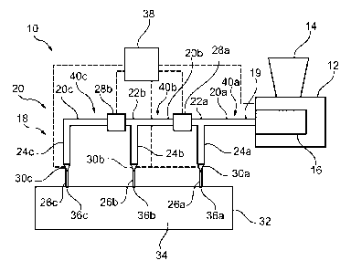
Fig.1 schematically shows an injection moulding system according to an
embodiment of the invention.
Fig.2 shows a three dimensional view of a distribution system according to an
embodiment of the invention.
Fig. 3 shows a flow diagram for an injection moulding method according to an
embodiment of the invention.
In principle, identical parts are provided with the same reference symbols in
the
figures.
DETAILED DESCRIPTION OF EXEMPLARY EMBODIMENTS
Fig. 1 shows an injection moulding system 10 with a supply system 12, a
distribution system 18, a mould 32 and a control unit 38.
The supply system 12 for supplying the distribution system 18 with hot liquid
plastic material (for example a polymer thermoplastic) comprises a hopper 14,
which
is adapted for providing granulate of the plastic material to a dosing system
16. The
dosing system 16 may comprise a barrel for melting the plastic material and a
CA 02850855 2014-04-02
WO 2013/053664 PCT/EP2012/069840
(hydraulic, electrical) device which, by for example translational movement of
the
barrel, controls the mass flow rate of the liquid plastic material to the
distribution
system 18 (in a injection phase of the system 10) and/or the pressure level
(in the
packing phase of the system 10).
5
The supply system 12 comprises an outlet connected to an inlet 19 of the
distribution system 18.
The distribution system 18 comprises a distributor (hotrunner) 20 for
distributing
10 the liquid plastic material from the supply system 12 to different gates
36a, 36b, 36c
into the mould cavity 34. The distribution system 18 comprises nozzles 24a,
24b, 24c
which are connected to the gates 36a, 36b, 36c and are adapted for injecting
liquid
plastic material into the mould cavity 34.
Outlets of the nozzles 24a, 24b, 24c are connected to the gates 36a, 36b, 36c.
The distributor 20 (which may be a distributor line 20) comprises hot channels
or
lines 20a, 20b, 20c interconnected via branching points 22a, 22b which
distribute the
liquid plastic material to the nozzles 24a, 24b, 24c. Outlets of the
distributor 20 are
connected to inlets of the nozzles 24a, 24b, 24c. The distributor 20 and the
lines 20a,
20b, 20c may be heated.
The nozzles 24a, 24b, 24c may optionally comprise nozzle valves 30a, 30b, 30c
for opening and closing the respective outlet of the nozzle 24a, 24b, 24c. The
nozzle
valves 30a, 30b, 30c may be needle valves and may be controlled by the control
unit
38, which may also control the supply system 12.
CA 02850855 2014-04-02
WO 2013/053664 PCT/EP2012/069840
11
The outlets of the nozzles 24a, 24b, 24c may be connected to inlets of
optional
cold channels 26a, 26b, 26c, which have outlets that provide the gates 30a,
36b, 30c
to the mould cavity 34. The cold channels 26a, 26b, 26c may be seen as a
coldrunner
26. The coldrunner 26 and the cold channels 26a, 26b, 26c are not heated and
may be
cooled.
The mould 32 comprises a mould cavity 34 and the gates 36a, 36b, 36c, which
either connect the outlets of the nozzles 24a, 24b, 24c or the outlets of the
coldrunner
26 with the inlets of the mould cavity 34. The mould cavity 34 is the cavity
of the
system 10 forming the volume of the part to be moulded.
The distribution system 18 further comprises distributor valves 28a, 28b that
may
be needle valves and that may only be adapted to close and open completely.
The
distributor valves 28a, 28b may be controlled by the control unit 38.
With the distribution system 18, several flow paths 40a, 40b, 40c for liquid
plastic
material are defined between the inlet 19 and the gates 30a, 36b, 30c of the
mould
32.
The first flow path 40a starts at the inlet 19 and comprises the line 20a, the
branching point 22a, the nozzle 24a and the cold channel 26a and ends at the
gate
36a.
The second flow path 40b starts at the inlet 19 and comprises the line 20a,
the
branching points 22a, the line 20b, the branching point 22b, the nozzle 24b
and the
cold channel 26b and ends at the gate 36b. The second flow path 40b may be
interrupted with the distributor valve 28a (directly) after the branching
point 22a.
CA 02850855 2014-04-02
WO 2013/053664 PCT/EP2012/069840
12
The third flow path 40c starts at the inlet 19 and comprises the lines 20a,
20b, 20c,
the branching points 22a, 22b, the nozzle 24c and the cold channel 26C and
ends at
the gate 36C. The third flow path 40c may be interrupted with the distributor
valve
28b (directly) after the branching point 22b or with the distributor valve 28a
(directly) after the branching point 22a.
With the distributor valves 28a, 28b, the flow paths 40b, 40c may be
interrupted
or closed in such a way that only liquid plastic material may enter the parts
of the
distribution system 18 that are needed for a mass flow to one of the gates
36a, 36b,
36c. The parts of the distribution system 18 that would be subjected for being
filled
with plastic material under pressure without mass flow are disconnected from
the rest
of the distribution system 18.
Fig. 2 shows a three dimensional view of a distribution system 18 that may be
used for moulding a bumper 42. The distribution system 18 may comprise a
supply
line 44 for supplying liquid plastic material from the inlet 19 to the
distributor 20.
The translational movement of the barrel of the dosing system 16 may be the
only
energy source for filling the mould cavity 34 in the injection phase and to
pressurize
the liquid plastic material injected in the packing phase until it cools down
and
solidifies. Only with the translational movement of the barrel, the mass flow
rates
and the pressure of the liquid plastic material filling the mould cavity 34
may be
controlled.
In the distribution system 18 with more than one gate 36a, 36b, 36c, the
individual
mass flow rates through the distributor 20 and the nozzles 24a, 24b, 24c
becomes
CA 02850855 2014-04-02
WO 2013/053664 PCT/EP2012/069840
13
more complex. In this case, the individual mass flow rate of any flow path
40a, 40b,
40c directly depends on the pressure resistance at a specific time. Generally
spoken,
flow paths with high pressure resistance will have a reduced mass flow at a
specific
time and vice versa. The total mass flow through the distribution system 18 is
determined with the translational movement of the barrel and correspond with
the
mass flow rate at the entrance of the distribution system 18.
Consequently, flow paths 40a, 40b, 40c of a distribution system 18 defined by
infinite flow resistance will have a mass flow rate of zero. This, for
instance, is the
case, if a certain shutoff nozzle 24a, 24b, 24c or distribution valve 28a, 28b
of the
distribution system 18 is closed at a specific time of the injection phase.
Due to a infinite flow resistance of a flow path 40a, 40b, 40c, the volume of
the
liquid plastic material becomes pressurized instead in the respective flow
path 40a,
40b, 40c. The pressure level of the liquid plastic material within the flow
path 40a,
40b, 40c will thereby correspond with the pressure level of the liquid plastic
material
at a position, where the mass flow rate at the same time is not zero, i.e. the
branching
points 22a, 22b.
Due to the pressure of liquid plastic material without any mass flow rate the
liquid
plastic material is compressed and energized. The energy is temporarily stored
in the
liquid plastic material. Therefore, the temporarily energized volume of the
liquid
plastic material (between the branching point 22a, 22b and the outlet of the
nozzle
24a, 24b, 24c) influences the controllability of the mass flow rate of
injection
moulding process. With the distribution valves 28a, 28b, the amount of liquid
plastic
material without mass flow may be minimized and the controllability of the
system
10 may be enhanced.
CA 02850855 2014-04-02
WO 2013/053664 PCT/EP2012/069840
14
Fig. 3 shows a flow diagram for a injection moulding method that may be
automatically performed with the moulding system 10 under the control of the
control unit 38.
In step S10 liquid plastic material is molten in the supply system 12 and
pressed
into the distribution system 18 by the dosing system 16.
In step S12, the liquid plastic material is injected into the mould cavity 34
over the
nozzle 24a. The liquid plastic material flows over the first flow path 40a to
the first
nozzle 24a. Due to the closed distributor valve 28a, liquid plastic material
is
prevented from entering the second flow 40b path to a second nozzle 24b.
In step S14, the control unit 38 opens the distributor valve 28a such that
liquid
plastic material enters the second flow path 40b and in particular the hot
channel line
30b. When the nozzle 24a is a shutoff nozzle, the nozzle 24a may be closed
after the
opening of the distribution valve 28a. However, the mass flow of liquid
plastic
material through the nozzle 24a may be stopped when the mould cavity 34 is
completely filled in the area of the nozzle 24a.
In step S16, liquid plastic material is injected over the second flow path 40b
and
via the nozzle 24b into the mould cavity.
The steps S14 and S16 may be repeated in a similar fashion for the third flow
path
40c and the second distributor valve 28.
CA 02850855 2014-04-02
WO 2013/053664 PCT/EP2012/069840
With the system 10, an sequential injection moulding processes may be
performed
with opening/closing sequences of the distribution valves 28a, 28b and
optionally of
the individual shutoff nozzles 24a, 24b, 24c.
5 The flow rate of the liquid plastic material through the individual
gates 36a, 36b,
36c during the injection phase is of high importance as it directly determines
the flow
front speed of the liquid plastic material filling the mould cavity 34. High
quality
processes target constant flow front speeds of the melt filling the part
cavity.
10 With the system 10, at any time of the process an exact controllability
of the mass
flow rate and flow front speeds (gating location) in the mould cavity 34 is
possible.
With the system 10, the throughput through the gates ,may be controlled via
the
supply system 12 so, that the flow front speed within the mould cavity 34 over
the
15 injection moulding phase is constant all the time. Otherwise, surface
defects, shear
heating, shear layered structure, tiger stripes, extensive melt temperature
would
occur.
With the system 10, volumes without mass flow may be avoided, which store
energy and which may hinder a direct control (energy communication) from the
energy source (controlled movement of the barrel) to the gating location 36a,
36b,
36c of the mould cavity 34.
While the invention has been illustrated and described in detail in the
drawings
and foregoing description, such illustration and description are to be
considered
illustrative or exemplary and not restrictive; the invention is not limited to
the
disclosed embodiments. Other variations to the disclosed embodiments can be
CA 02850855 2014-04-02
WO 2013/053664
PCT/EP2012/069840
16
understood and effected by those skilled in the art and practising the claimed
invention, from a study of the drawings, the disclosure, and the appended
claims. In
the claims, the word "comprising" does not exclude other elements or steps,
and the
indefinite article "a" or "an" does not exclude a plurality. A single
processor or
controller or other unit may fulfil the functions of several items recited in
the claims.
The mere fact that certain measures are recited in mutually different
dependent
claims does not indicate that a combination of these measures cannot be used
to
advantage. Any reference signs in the claims should not be construed as
limiting the
scope.