Note: Descriptions are shown in the official language in which they were submitted.
CA 02850918 2014-04-02
WO 2013/052001
PCT/SE2012/051063
1
Method and apparatus for detecting lameness in livestock
Technical Field
The present invention concerns the detection of lameness in livestock. In
particular, it relates to the non-invasive detection of lameness in cattle,
but also
to other four-legged animals, such as horses, sheep and goats.
Background
All livestock is subject to lameness but dairy animals and specifically dairy
cows
are particularly vulnerable, due in part to the weight they carry, but also to
their
accommodation. In many modern diary farms cows are confined all year round
in confinement systems with concrete floors. Over time, this surface can
damage the hoof leading to lameness. Even in dairy farms that are pasture
based, the animals have to stand on concrete floors in the milking parlour at
least twice a day. In addition, the floor of the milking parlour is often wet,
which
can encourage infection.
Lameness can lead to a reduction in feed intake, a reduction in milk
production
and weight loss. Thus lameness has a drastic effect on the performance of a
dairy animal. Lameness is conventionally detected by a herdsman by observing
the movement of the animal and will often only be picked up once it has become
severe requiring immediate and often costly treatment. Once an animal
becomes lame, it can take several months to recover. Lameness thus
represents a significant cost for livestock breeders and farmers in terms of
time,
financial expenditure for veterinary services, medication and treatment, and
also
for loss in production.
It is thought that the early detection of lameness can mitigate these losses
as
early treatment may enable an animal to recover more rapidly. A number of
automatic lameness detection systems are known, however, these require the
animal to perform some kind of movement, sometimes under controlled
conditions, which, in a farm environment is often not practical or cost
effective.
US 6,699,207 proposes a diagnostic system for detecting lameness in dairy
cattle which consists of a system of plates placed over load cells provided at
CA 02850918 2014-04-02
WO 2013/052001
PCT/SE2012/051063
2
floor level and over which the animals must walk. The system determines and
analyses the animal's limb reaction forces, weight, bilateral symmetry of limb
reaction forces and other factors as the animal passes over the plates and
compares these with reference data obtained when a healthy animal passes
over the plate. The drawback of this system is that reference data must be
provided, preferably for each animal, requiring all animals to walk over the
system when healthy at least once. The system of plates is also cumbersome
and large requiring adequate floor space and considerable installation costs.
Further systems propose the attachment of sensors to the animal to detect
abnormal movement. A problem with these systems is how to ensure that the
sensors remain fixed on the animal in what may be an inherently dirty
environment without reverting to invasive techniques that require costly
veterinary or specialist intervention and may cause unnecessary distress to
the
animal. WO 2006/009959 describes a system for monitoring the condition and
wellbeing of dairy animals that includes a monitor unit fixed to a collar,
strap,
transdermal patch or ingested bolus carried by the cow that includes a number
of sensors, one of which is an accelerometer. Lameness is determined by
analysing the signals from the accelerometer to detect an abnormal gait, which
could indicate lameness. A fixed unit is provided which collects data from the
monitoring unit wirelessly and analyses this. A problem with this system is
the
complexity of the signals that will be produced as any movement of the cow,
including raising or lowering its head, will be registered by the
accelerometer.
Added to this is the difficulty in ensuring that the accelerometer does not
move
on the cow. Moreover, determining signals that indicate an abnormal gait and
possible lameness is complex and prone to error, resulting in unreliable
results.
WO 2006/009959 proposes a similar system for monitoring the gait of a horse
wherein patches consisting of piezoelectric film are attached to each hoof of
the
horse. The signals produced are analysed and compared to reference signals,
which are collected from the same animal or a group of other animals
previously.
This system must be used in a controlled and clean environment as the location
of the sensors on the hooves of the animal would otherwise put them at risk of
damage.
There is thus a need to improve on the automatic early detection of lameness.
CA 02850918 2014-04-02
WO 2013/052001
PCT/SE2012/051063
3
Summary
It is an object of the present invention to overcome the disadvantages of
prior art
arrangement and provide a device and method for detecting lameness in
animals at an early stage that is simple to install, does not impact on the
animal's normal routine and provides a rapid result.
This and further objects of the invention are provided in a device for
detecting
lameness in a standing animal comprising at least one optical imaging device,
and a processing arrangement coupled with the optical imaging device. The
optical imaging device is arranged in a position to capture at least one image
showing the lower portions of at least one leg of an animal and to forward a
captured image to the processing arrangement, wherein the processing
arrangement is configured to analyse the image of said at least one leg to
determine a condition of lameness when said at least one leg is held in a
raised
position on or above a floor surface.
It has been observed that when an animal is or is becoming lame, it tends to
slightly lift the leg in question so as not to put weight on it when standing.
By
detecting whether a leg is held in a position, that differs from the normal
flat
standing position, whether in contact with a floor surface or held above this
surface , the device is able to provide an early indicator of a possible
problem to
the farmer or stockman enabling further investigation and treatment. In
this
context, a raised position is intended to mean a position in which the
animal's leg
or foot will not bear the weight of the animal and thus defines a position in
which
the lower surface of the foot is not in contact with the floor over the whole
of its
surface. Furthermore, a floor surface may be a substantially flat surface
designed to support the animal, or be composed of different levels with raised
profiles or dips which encourage an animal to stand with her legs in a
particular
position to facilitate an operation such as cleaning, inspection or milking.
In this
case any part of the floor surface may be viewed as a reference surface for
determining whether a leg is raised or not.
Preferably, the optical imaging device is adapted to capture a plurality of
images
CA 02850918 2014-04-02
WO 2013/052001
PCT/SE2012/051063
4
at intervals over a predetermined period of time to ensure that the animal's
leg is
indeed held in a raised position and that an image has not been captured while
the animal shifts its position.
In accordance with a preferred embodiment of the invention, the device
includes
an identification unit that is coupled to the processing arrangement and is
arranged to communicate with a transponder carried by the animal and to
extract
from the transponder an identification code associated with the animal. By
automatically identifying the animal through its code it is possible, firstly,
to
detect lameness in an individual subject without the presence of a herdsman
and, secondly, to store this information individually for each animal as part
of a
larger health and/or production record. This data can then be used to monitor
the progression of an ongoing condition, or to provide statistics for
individual
animals or a herd of animals.
Preferably, the optical imaging device comprises a camera. This may be a time
of flight camera, which provides a depth measurement and thus a 3D image.
Alternatively, the camera may be one that generates a 2D image, such as a
CCD camera. Advantageously, the device comprises at least two cameras,
enabling a 3D image to be generated using lower cost 2D cameras and
additionally or alternatively to enable all legs of an animal to be viewed
without
obstruction.
In a particularly advantageous and cost-effective embodiment of the present
invention, the camera is arranged to be used as part of an automatic or semi-
automatic milking arrangement for enabling the determination of the position
of
the teats of a dairy animal. Such cameras are commonly used to determine the
teat positions to enable teat cleaning, teat cup attachment and/or aftercare
treatment. Combining a lameness detection function in the milking arrangement
is a relatively simple modification and permits the detection to take place
while
the animal is confined and stationary as part of her normal routine.
The optical imaging device may conveniently be arranged in an animal stall
having at least a floor surface, and be located in a position wherein the
device is
5
able to capture an image of at least one leg on or near the floor surface.
This
likewise ensures that the device can operate while the animal is at least
partially
confined, stationary and at close proximity to the device. Integrating the
device
in a feeding stall or a milking stall further ensures that the animal is
occupied and
substantially stationary for sufficient time to enable the device to operate.
The invention further resides in a milking stall comprising a lameness
detection
device, an automatic milking arrangement including a device for detecting
lameness and a method for monitoring the condition of an animal in accordance
with the appended claims.
In one aspect, there is provided a method of detecting lameness in a standing,
stationary animal, the method comprising the steps of: automatically
capturing, using
an optical imaging device, an image of a lower portion of a leg of the animal
while the
animal is standing and stationary, the lower portion of the leg in the image
including a
hoof of the leg, the hoof having a lower surface defining a first contact
surface with a
floor surface when the animal is standing and stationary on the floor surface;
receiving
the image at a processor arrangement in communication with said optical
imaging
device; and analyzing, at the processor arrangement, the image and generating,
based
on said analyzing, a determination indicating whether the lower leg captured
by the
image is in one of i) a flat position wherein the hoof is flat in contact with
the floor, or ii)
in a raised position wherein the hoof is either not flat against the floor
surface or is
distanced above the floor surface; the processor arrangement outputting a
determination of lameness in the animal when the determination indicates that
the
lower portion of a leg of the animal in the image is in the raised position.
In one aspect, there is provided a system that detects lameness in a standing,
stationary animal, the system comprising: an optical imaging device that
automatically
captures an image of a lower portion of a leg of the animal while the animal
is standing
and stationary, the lower portion of the leg in the image including a hoof of
the leg, the
hoof having a lower surface defining a first contact surface with a floor
surface when
the animal is standing and stationary on the floor surface; a processor
arrangement in
communication with said optical imaging device and that receives the captured
image
transmitted by the optical imaging device, the processor arrangement
configured to
analyze the image and generate, based on said analyzing of the image, a
CA 2850918 2019-01-28
5a
determination indicating whether the lower leg is in either of i) a flat
position wherein
the hoof is flat in contact with the floor, or ii) in a raised position
wherein the hoof is
either not flat against the floor surface or distanced above the floor
surface, and outputs
a determination of lameness in the animal when the determination indicates
that the
lower portion of a leg of the animal in the image is in the raised position.
Brief description of the drawings
Further objects and advantages of the present invention will become apparent
from the following description of the preferred embodiments that are given by
way of example with reference to the accompanying drawings. In the figures:
Fig. 1 schematically illustrates a lameness detection device in
accordance with one embodiment of the present invention,
Fig. 2 schematically illustrates an alternative view of the
lameness
detection device of Fig. 1, and
Fig. 3 shows the rear legs of an animal illustrating a possibly
lame leg.
Detailed description
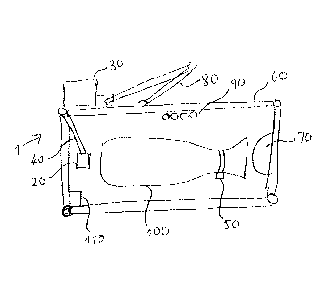
Referring to Fig. 1 there is shown a stall, which in the exemplary embodiment
is
a milking stall 60 for milking dairy cows, in which is arranged a device for
detecting lameness 'I in accordance with the present invention. As shown in
Fig.
1, the stall 60 is made up of wall sections, which are essentially bars or
barriers,
one side of which may open to allow the entrance and exit of the animal_ The
outline of a cow 100 is also depicted in the stall 60. The stall 60 is further
provided with a floor, which is not illustrated in detail. The floor is a
hard,
essentially planar surface and is preferably kept free of any soft material,
such
as straw, sawdust, sand or the like that may impede a clear view of an animals
CA 2850918 2019-01-28
CA 02850918 2014-04-02
WO 2013/052001
PCT/SE2012/051063
6
legs. However, the floor may include sections of different height and/or slope
designed to prevent an animal placing her legs in certain areas and so to
encourage a position that facilitates treatment, At the rear of the stall
there is
arranged a device for detecting lameness 1, which includes a processor 30 and
an optical imaging element 20 that is coupled to the processor 30. The
connection between the optical imaging element 20 and processor 30 may be
achieved via a wire link. Alternatively, the connection may be wireless, for
example, using infrared radiation or a wireless radio protocol, such as
Bluetooth.
The processor 30 includes data processing circuitry, such as a microprocessor
or mini computer together with programme and data memory. The optical
imaging element 20 is a camera, preferably a time of flight (TOF) camera,
which
permits a 3 dimensional image to be generated using a single image by emitting
light pulses and for each pixel determining the time for light to be reflected
back
from an object. Cameras of this kind are well-known in the art and will not be
described in more detail here. An example of a suitable camera is the SR4000
offered for sale by MESA Imaging AG,. Further cameras are available from LMI
Technologies Inc. and Fotonic Alternatively, the optical imaging element could
be a CCD camera, or an arrangement of two or more TOF or CCD cameras. In
the illustrated embodiment, the optical imaging element 20 is mounted on an
arm 40 that may be movable and controllable by the processor 30 to change the
position of the element 20. In particular, the arm may be articulated and/or
telescopic allowing the displacement of the optical imaging unit 20 in the
stall 60.
In alternative embodiments the arm 40 may be fixed or the optical imaging
element 20 fixedly mounted on part of the stall or on a separate arrangement
on
or near the floor.
An identification unit 110 is also disposed in the stall 60 and is coupled to
the
processor 30. Each animal is furthermore provided with a transponder 50 that
stores a code identifying the animal. The transponder 50 may be carried on a
collar around the animal's neck as shown in the figure, or be affixed to any
other
convenient attachment arrangement, such as an ear tag, head collar or leg
strap. When an animal approaches the identification unit 110, the unit
interrogates the transponder 50 to obtain the animal's identification code.
CA 02850918 2014-04-02
WO 2013/052001
PCT/SE2012/051063
7
In the illustrated embodiment, the processor 30 is part of an automatic
robotic
milking system that includes a robot arm with gripper 80 that is able to pick
up
teat cups 90, either individually or collectively, carry these to the teats of
a cow
and attach each one to a teat. The robot arm 80 may also convey other
equipment towards the teats, such as a cleaning device or a device for
effecting
a post-milking or after-care treatment. The various components and function of
such a system are generally known in the art and will not be described in
detail
here. When the processor 30 receives an identification code of an animal from
the identification unit 110 it may use this code to call up data stored for
the cow
in question, which may include the expected milk yield, the dimensions of the
animal, the last known position of the teats and/or general health
information.
Advantageously, the optical imaging element 20 may also form part of the
automatic robotic milking system and be used to determine the position of the
udder and teats of an animal in order to allow the udder and/or teats to be
cleaned by automatic cleaning means, to attach teat cups to each teat for
milking and/or to automatically perform an after-treatment on the teats, such
as a
spray disinfectant, or the like. At the front end of the stall there is
arranged a
manger 70, into which a suitable feed such as concentrate is dispensed,
preferably by means of an automatic feed dispensing arrangement that may also
be coupled to the processor 30.
Turning now to Fig. 2 there is shown a rear side view of the milking stall 60
with
the processor 30 shown to the left of the figure and the optical imaging unit
20
mounted on an arm 40, also mounted on a beam of the milking stall 60 to the
left
of the stall. As can be seen in Fig. 2, the optical imaging unit 20 is located
at a
position above the floor behind the animal 100 where it can capture an image
of
the lower part of at least one leg of the animal 100, but preferably of more
than
one leg. Depending on the stance of the animal 100 and the position of other
equipment within the stall, it may be possible for the optical imaging unit 20
to
capture an image that shows the lower part of all four legs of the animal 100.
The operation of the arrangement is as follows. When an animal 100 enters the
milking stall 60 it is identified by the identification unit 110 which obtains
the
identification code from the transponder 50 attached to the animal 100. The
CA 02850918 2014-04-02
WO 2013/052001
PCT/SE2012/051063
8
animal 100 will then be milked according to the normal procedure, possibly
preceded with cleaning and preparation and/or succeeded by an after treatment.
The lameness detection device may be activated prior, during or after this
milking operation. This is achieved by activating the optical imaging unit 20
to
produce one or more images of the space within the stall 60. For the purpose
of
detecting lameness, the image captured must include at least one lower leg of
the animal 100 and preferably all legs. When the optical imaging unit 20 is
also
used to determine the position of the teats of the animal 100 it may be
possible
to use a single image for both purposes. The signals captured by the optical
imaging unit 20 are relayed to the processor 30 where the image or images are
processed using a suitable algorithm to determine the objects and their
various
positions in the field of view.
When processing the image to detect lameness, the algorithm is designed to
first
identify objects as the legs of the animal and secondly to recognise a hoof
that is
not placed flat on the ground. Reference is made in this regard to Fig. 3.
Fig, 3
shows the lower part of the rear legs of the animal illustrated in Fig. 2. The
left-
hand hoof 100a is standing normally on the floor with the hoof flat and in
contact
with the floor. In contrast, the right-hand hoof 100b is not flat, but instead
is
raised slightly. The hoof may not be lifted completely from the floor to
create a
space between the hoof and the floor. However, the act of raising the leg
slightly
alters the silhouette of the hoof and also the three-dimensional shape of the
hoof, so that it is possible to identify the anomaly based on the hoof shape.
The
same is true when an animal is lame in a front leg. The change in the
silhouette
means that it is possible to identify the raised leg even when a single 2D
camera, e.g. a CCD camera, is used rather than a TOF camera that can provide
a 3D image. Since it is possible that an animal may shift position in the
stall
from time to time, the optical imaging unit 20 is arranged to capture a number
of
images spaced at intervals and to compare the images to determine whether
one or more hooves are held in an abnormal position during a predetermined
period of time. For example, a hoof detected in a raised position in five
successive images captured at intervals of around 2s over a period of around
8s
would establish whether one or more of the animal's hooves are raised while
the
animal is stationary. Clearly this is only an example, and a series of fewer
or of
CA 02850918 2014-04-02
WO 2013/052001
PCT/SE2012/051063
9
more images may be used, while the intervals between successive images may
also be adjusted.
While in the illustrated embodiment, the optical imaging unit 20 is located at
the
rear of a stall and effectively views the front legs of the animal through the
animal's rear legs, it is likewise possible to place the optical imaging unit
20 at a
different position, e.g. at the side or even the front of the stall. When
placed at
the side of the stall, the camera could be arranged to pivot to enable two
images
to be taken, one of the front legs and the other of the rear legs.
Alternatively, or
in addition, two ore more cameras could be located around the stall 60 to
ensure
a clear view of all legs. This can also be used to generate a 3D image when 2D
cameras, such as CCD cameras are used.
Once a possible lame leg has been detected using the device 1, this
information
can be stored together with the animal's identification code. An alert message
may be produced, either on a display, or in the form of a printout.
Alternatively,
an alert message may be transmitted to a remote terminal, such as a remote pc,
mobile phone or other portable communication devices to make the stockman
aware of the animal's condition.
The advantage of locating the lameness detection device 1 in a milking stall
is
that the animal will remain standing for a certain period of time and it is
possible
to determine whether the animal is holding one or more of its legs away from
the
floor, Naturally, this is true regardless of the manner in which the animal is
being
milked, whether milking is fully automatic, semi-automatic with some
procedures
being carried out manually or manual. The device 1 can also be integrated in
any form of parlour, i.e. a single or tandem milk box, a parlour with multiple
milking stalls or a rotary platform parlour, The lameness detection device 1
can
advantageously be integrated in a milking system and the periphery devices
surrounding this system, so that the identification and alert functions of
this
system can be used for the detection of lameness. However, it is equally
possible to provide the lameness detection device 1 as a stand-alone device.
Locating the lameness detection device at a milking stall also enables
detection
to be performed regularly, possibly more than twice a day, so that an abnormal
CA 02850918 2014-04-02
WO 2013/052001
PCT/SE2012/051063
condition can be detected at the earliest possible stage. The lameness
detection device 1 may also be arranged at other locations where animals are
likely to stand for a period for time and, ideally, where they can be
identified
automatically. This includes feeding stalls, but also selection or sorting
stalls,
5 which could permit animals with suspected lameness to be diverted into a
separation area, where they can subsequently be examined and, if necessary,
treated. Such a selection or sorting stall could be placed in between areas
that
are subject to high traffic, for example between feeding and resting areas or
a
milking parlour and pasture so that the animals are routinely checked for
10 lameness or the onset of lameness. The animal could be provided with
fodder
or concentrate in such a selection stall to encourage the animal to remain
calm
and stationary during lameness detection. The lameness detection device 1
could even be located at another area where animals naturally congregate
without being confined in a stall, for example at a feeding table.