Note: Descriptions are shown in the official language in which they were submitted.
CA 02851416 2014-04-07
WO 2013/052819
PCT/US2012/058988
-1-
Description
GROUND ENGAGING IMPLEMENT TOOTH ASSEMBLY WITH TIP AND ADAPTER
Technical Field
This disclosure relates generally to earth working machines with
ground engaging implements and, in particular, to tooth assemblies with
replaceable tip and adapter systems attached to the leading or base edges of
such
ground engaging implements.
Background
Earth moving machines known in the art are used for digging into
the earth or rock and moving loosened work material from one place to another
at
a worksite. These machines and equipment typically include a body portion
housing the engine and having rear wheels, tracks or similar components driven
by the engine, and an elevated cab for the operator. The machines and
equipment
further include articulating mechanical arms or other types of linkages, such
as Z-
bar linkages, for manipulating one or more implements of the machine. The
linkages are capable of raising and lowering the implements and rotating the
implements to engage the ground or other work material in a desired manner. In
the earth moving applications, the implements of the machines or other
equipment are buckets provided with a beveled lip or blade on a base edge for
moving or excavating dirt or other types of work material.
To facilitate the earth moving process, and to prolong the useful
life of the implement, a plurality of tooth assemblies are spaced along the
base
edge of the implement and attached to the surface of the implement. The tooth
assemblies project forward from the base edge as a first point of contact and
penetration with work material, and to reduce the amount of wear of the base
edge. With this arrangement, the tooth assemblies are subjected to the wear
and
CA 02851416 2014-04-07
WO 2013/052819
PCT/US2012/058988
-2-
breakage caused by repetitive engagement with the work material. Eventually,
the tooth assemblies must be replaced, but the implement remains usable
through
multiple cycles of replacement tooth assemblies. Depending on the variety of
uses and work material for the equipment, it may also be desirable to change
the
type or shape of the tooth assemblies to most effectively utilize the
implement.
In many implementations, installation and replacement of the
tooth assemblies may be facilitated by providing the tooth assemblies as a two-
part system. The system may include an adapter that is attached to the base
edge
of the implement, a ground-engaging tip configured to be attached to the
adapter,
and a retention mechanism securing the tip to the adapter during use. The
adapter
may be welded, bolted or otherwise secured to the base edge, and then the tip
may be attached to the adapter and held in place by the retention mechanism.
The tip endures the majority of the impact and abrasion caused by engagement
with the work material, and wears down more quickly and breaks more
frequently than the adapter. Consequently, multiple tips may be attached to
the
adapter, worn down, and replaced before the adapter itself must be replaced.
Eventually, the adapter may wear down and require replacement before the base
edge of the implement wears out.
One example of a digging tooth assembly is illustrated and
described in U.S. Pat. No. 4,949,481 to Feliner. The digging tooth for a
bucket
has a concave top surface and a convex bottom surface which intersect forming
a
forward cutting edge. Sidewalls connect the two surfaces and are concave
having
a moldboard shape. The rear portion of the tooth is provided with a mounting
assembly for mounting the digging tooth to a bucket. The bottom surface
continuously diverges from the forward cutting edge to the rear portion;
whereas
the top surface first converges then diverges from the forward cutting edge to
the
rear portion. The rear portion includes a shank receiving cavity with top and
bottom walls that converge as the cavity extends forwardly within the tooth to
give the cavity a triangular or wedge shape when viewed in profile.
CA 02851416 2014-04-07
WO 2013/052819
PCT/US2012/058988
-3 -
An example of a loader bucket tooth is provided in U.S. Pat. No.
5,018,283 to Fellner. The digging tooth for a loader bucket includes a top
surface
having a concave configuration and a bottom surface having a flat forward
portion and a convex rear portion. The flat forward portion and the top
surface
intersect to form a fonward cutting edge. Sidewalls connect the two surfaces
and
are concave having a plowshare shape. The rear portion of the tooth is
provided
with a mounting assembly for mounting it to a bucket. The bottom surface
continuously converges from the forward cutting edge to the rear portion;
whereas the top surface first converges then diverges from the forward cutting
edge to the rear portion. The rear portion includes a shank receiving cavity
with
bottom wall extending inwardly, and a top wall having a first portion
extending
approximately parallel to the bottom wall and a second portion angled toward
the
bottom wall and extending to a rounded front portion.
U.S. Pat. No. 2,982,035 to Stephenson provides an example of an
excavator tooth having an adapter that attaches to the leading edge of a
dipper
body, and a tip that attaches to the adapter. The tip includes an upper
surface and
a lower surface that converge into a relatively sharp point, with the tip
having a
horizontal plane of symmetry. Upper and lower surfaces of the adapter have
recessed central surfaces, with the upper central surface having a forward
surface
that diverges upwardly from the plane of symmetry and rounds into a forward
surface of the adapter. The interior of the tip has corresponding planar
surfaces
that are received by the central surfaces of the adapter, and include forward
surfaces diverging from the plane of symmetry as they approach a forward
surface, with one of the forward surfaces of the tip abutting the forward
surface
of the adapter when the parts are appropriately assembled.
The implements as discussed may be used in a variety of
applications having differing operating conditions. In loader applications,
buckets installed on the front of wheel or track loaders have the bottom
surfaces
and base edges scrape along the ground and dig into the earth or pile of work
CA 02851416 2014-04-07
WO 2013/052819
PCT/US2012/058988
-4-
material as the loader machine is driven forward. The forces on the tooth
assembly as the bucket enters the pile push the tip into engagement with the
corresponding adapter. The bucket is then raised and racked with the load of
work material, and the loader moves and dumps the work material in another
location. As the bucket is raised through the work material, force is exerted
downwardly on the tooth assembly. With the combination of scraping and
engagement with the work material, and in other types of bottom-wearing
applications in which the bottom surface typically wears more quickly due to
more frequent engagement with the work material, the wear material of the tip
wears away from the front of the tip and from the bottom surface of the tip
and
adapter. The loss of wear material at the front of the tip converts the
initially
pointed front end of the tip into a rounded, blunt surface, similar to
changing the
hand from having extended fingers to having a closed fist. The worn down shape
is less efficient at digging through the work material as the loader moves
forward,
though the tip may still have sufficient wear material to be used on the
implement
for a time before replacement.
In excavator applications and other types of top-wearing
applications where the top surface typically wears more quickly due to more
frequent engagement with the work material, the buckets engage and pass
through the ground or work material at different angles than in bottom-wearing
applications such as loader applications described above, and therefore cause
wear material of the tooth assemblies to wear away in a different manner. An
excavator device, such as a backhoe, initially engages the work material with
the
base edge and tooth assemblies oriented close to perpendicular with respect to
the
surface of the work material and generally enter the work material in a
downward
motion. After the initial penetration into the work material, the mechanical
arm
further breaks up the work material and collects a load of work material in
the
bucket by drawing the bucket back toward the excavator machine and rotating
the
bucket inwardly to scoop the work material into the bucket. The complex motion
CA 02851416 2014-04-07
WO 2013/052819
PCT/US2012/058988
-5-
of the bucket causes wear at the tip of the tooth assembly during the downward
penetration motion when the forces act to push the tip into engagement with
the
adapter. After the initial penetration, the bucket is drawn toward the machine
and
rotated to further in a scooping motion to break up the work material and
begin to
load the implement. During this motion, the forces initially act in a
direction that
is initially mostly normal to the top surface of the tooth assembly, and the
work
material passes over and around the top of the tooth causing wear on the top
surface of the tooth. As the implement rotates further and is drawn through
the
work material, the forces and work material again act on the tip of the tooth
to
cause wear at the tip. As with the loader tooth assemblies, the excavator
tooth
assemblies wear down to less efficient shapes after repeated forays into the
work
material, but may still retain sufficient wear material for continued use
without
replacement. In view of this, a need exists for improved tooth assembly
designs
for loader and excavator implements that distribute the wear material such
that
the tips dig into the work material more efficiently as wear material wears
away
from and reshapes the tips until the tips ultimately must be replaced.
Summary of the Disclosure
In one aspect of the present disclosure, the invention is directed to
a ground engaging tip of a tooth assembly for a base edge of a ground engaging
implement, wherein the tooth assembly includes an adapter configured for
attachment to a base edge of the ground engaging implement and having a
forwardly extending adapter nose. The ground engaging tip may include a rear
edge, a top outer surface, a bottom outer surface, wherein the top outer
surface
and the bottom outer surface extend forward from the rear edge and converge at
a
front edge, oppositely disposed lateral outer surfaces extending downwardly
from
the top outer surface to the bottom outer surface, wherein the lateral outer
surfaces are tapered so that a distance between the lateral outer surfaces
decreases
as the lateral outer surfaces extend downwardly from the top outer surface
toward
the bottom outer surface, and an inner surface extending inwardly into the
ground
CA 02851416 2014-04-07
WO 2013/052819
PCT/US2012/058988
-6-
engaging tip from the rear edge and defining a nose cavity within the ground
engaging tip having a complementary shape to the adapter nose of the adapter
for
receiving the adapter nose therein.
In another aspect of the present disclosure, the invention is
directed to an adapter of a tooth assembly for a base edge of a ground
engaging
implement. The adapter may include a rearwardly extending top strap, a
rearwardly extending bottom strap having a top surface, wherein the top strap
and
the bottom strap define a gap there between for receiving the base edge of the
ground engaging implement, and a forward extending adapter nose. The nose
may include a bottom surface extending forward relative to the top strap and
the
bottom strap, a front surface, a top surface, oppositely disposed side
surfaces
extending downwardly from the top surface to the bottom surface, wherein the
side surfaces are tapered in a vertical direction such that a distance between
the
side surfaces decreases as the side surfaces extend downwardly from the top
surface toward the bottom surface.
In a further aspect of the present disclosure, the invention is
directed to a ground engaging tooth assembly for a base edge of a ground
engaging implement. The ground engaging tooth assembly may include an
adapter having a rearwardly extending top strap, a rearwardly extending bottom
strap having a top surface, wherein the top strap and the bottom strap define
a gap
there between for receiving the base edge of the ground engaging implement,
and
a forward extending adapter nose having a bottom surface extending forward
from the top strap and the bottom strap, a front surface, a top surface,
oppositely
disposed side surfaces extending downwardly from the top surface to the bottom
surface. The ground engaging tooth assembly may further include a ground
engaging tip having a rear edge, a top outer surface, a bottom outer surface,
wherein the top outer surface and the bottom outer surface extend forward from
the rear edge and converge at a front edge, oppositely disposed lateral outer
surfaces extending downwardly from the top outer surface to the bottom outer
81778568
- 7 -
surface, wherein the lateral outer surfaces are tapered so that a distance
between the lateral
outer surfaces decreases as the lateral outer surfaces extend downwardly from
the top outer
surface toward the bottom outer surface, and an inner surface extending
inwardly into the
ground engaging tip from the rear edge and defining a nose cavity within the
ground engaging
tip having a complementary shape to the adapter nose of the adapter for
receiving the adapter
nose therein.
According to one aspect of the present invention, there is provided a ground
engaging tip of a tooth assembly for a base edge of a ground engaging
implement, wherein the
tooth assembly includes an adapter configured for attachment to the base edge
of the ground
engaging implement and having a forwardly extending adapter nose, the ground
engaging tip
comprising: a rear edge; a top outer surface; a bottom outer surface, wherein
the top outer
surface and the bottom outer surface extend forward from the rear edge and
converge at a
front edge; oppositely disposed lateral outer surfaces extending downwardly
from the top
outer surface to the bottom outer surface, wherein the lateral outer surfaces
are tapered so that
a distance between the lateral outer surfaces decreases as the lateral outer
surfaces extend
downwardly from the top outer surface toward the bottom outer surface, and the
distance is
greater at an uppermost portion of the lateral outer surfaces than at a
lowermost portion of the
lateral outer surfaces; and an inner surface extending inwardly into the
ground engaging tip
from the rear edge and defining a nose cavity within the ground engaging tip
having a
complementary shape to the adapter nose of the adapter for receiving the
adapter nose therein,
wherein each of the lateral outer surfaces includes a projecting portion
extending outwardly
therefrom.
According to another aspect of the present invention, there is provided an
adapter of
a tooth assembly for a base edge of a ground engaging implement, the adapter
comprising: a
rearwardly extending top strap; a rearwardly extending bottom strap having a
top surface,
wherein the top strap and the bottom strap define a gap therebetween for
receiving the base
edge of the ground engaging implement; and a forward extending adapter nose
comprising: a
bottom surface extending forward relative to the top strap and the bottom
strap, a front
surface, a top surface, oppositely disposed side surfaces extending downwardly
from the top
CA 2851416 2018-11-22
81778568
- 7a -
surface to the bottom surface, wherein the side surfaces are generally planar
and are tapered in
a vertical direction such that a distance between the side surfaces decreases
as the side
surfaces extend downwardly from the top surface toward the bottom surface,
wherein each of
the side surfaces includes a projection extending outwardly therefrom.
According to still another aspect of the present invention, there is provided
a
ground engaging tooth assembly for a base edge of a ground engaging implement,
the ground
engaging tooth assembly comprising: an adapter, comprising: a rearwardly
extending top
strap, a rearwardly extending bottom strap having a top surface, wherein the
top strap and the
bottom strap define a gap therebetween for receiving the base edge of the
ground engaging
implement, and a forward extending adapter nose, comprising: a bottom surface
extending
forward from the top strap and the bottom strap, a front surface, a top
surface, oppositely
disposed side surfaces extending downwardly from the top surface to the bottom
surface, and
a ground engaging tip, comprising: a rear edge, a top outer surface, a bottom
outer surface,
wherein the top outer surface and the bottom outer surface extend forward from
the rear edge
and converge at a front edge, oppositely disposed lateral outer surfaces
extending downwardly
from the top outer surface to the bottom outer surface, wherein the lateral
outer surfaces are
tapered so that a distance between the lateral outer surfaces decreases as the
lateral outer
surfaces extend downwardly from the top outer surface toward the bottom outer
surface, and
wherein each of the lateral outer surfaces includes a projecting portion
extending outwardly
therefrom, and an inner surface extending inwardly into the ground engaging
tip from the rear
edge and defining a nose cavity within the ground engaging tip having a
complementary
shape to the adapter nose of the adapter for receiving the adapter nose
therein.
Brief Description of the Drawings
Fig. 1 is an isometric view of a loader bucket having tooth assemblies in
accordance with the present disclosure attached at a base edge thereof;
Fig. 2 is an isometric view of an excavator bucket having tooth assemblies in
accordance with the present disclosure attached at a base edge thereof;
CA 2851416 2018-11-22
81778568
- 7b -
Fig. 3 is an isometric view of a tooth assembly in accordance with the present
disclosure;
Fig. 4 is a side view of the tooth assembly of Fig. 3;
Fig. 5 is an isometric view of an adapter of the tooth assembly of Fig. 3;
Fig. 6 is a side view of the adapter of Fig. 5 attached to a base edge of an
implement;
Fig. 7 is a top view of the adapter of Fig. 5;
Fig. 8 is a bottom view of the adapter of Fig. 5;
Fig. 9 is a cross-sectional view of the adapter of Fig. 5 taken through line 9-
9 of
Fig. 7;
Fig. 10 is an isometric view of a tip of the tooth assembly of Fig. 3;
CA 2851416 2018-11-22
CA 02851416 2014-04-07
WO 2013/052819
PCT/US2012/058988
-8-
Fig. 11 is a side view of the tip of Fig. 10;
Fig. 12 is a top view of the tip of Fig. 10;
Fig. 13 is a bottom view of the tip of Fig. 10;
Fig. 14 is a front view of the tip of Fig. 10;
Fig. 15 is a cross-sectional view of the tip of Fig. 10 taken through
line 15 ____ 15 of Fig. 12;
Fig. 16 is a cross-sectional view of the tip of Fig. 10 taken through
line 16--16 of Fig. 14;
Fig. 17 is a rear view of the tip of Fig. 10;
Fig. 18 is an isometric view of an alternative embodiment of a tip
for a tooth assembly in accordance with the present disclosure;
Fig. 19 is a top view of the tip of Fig. 18;
Fig. 20 is a front view of the tip of Fig. 18;
Fig. 21 is a side view of the tip of Fig. 18;
Fig. 22 is a cross-sectional view of the tip of Fig. 18 taken through
line 22 ____ 22 of Fig. 19;
Fig. 23 is an isometric view of an alternative embodiment of an
adapter for an tooth assembly in accordance with the present disclosure;
Fig. 24 is a side view of the adapter of Fig. 23;
Fig. 25 is a cross-sectional view of the adapter of Fig. 23 taken
through line 25 __ 25 of Fig. 24;
Fig. 26 is an isometric view of an alternative embodiment of a tip
for a tooth assembly in accordance with the present disclosure;
Fig. 27 is a side view of the tip of Fig. 26;
Fig. 28 is a front view of the tip of Fig. 26;
Fig. 29 is a top view of the tip of Fig. 26;
Fig. 30 is a cross-sectional view of the tip of Fig. 26 taken through
line 30-30 of Fig. 29;
CA 02851416 2014-04-07
WO 2013/052819 PCT/US2012/058988
-9-
Fig. 31 is an isometric view of a further alternative embodiment of
a tip for a tooth assembly in accordance with the present disclosure;
Fig. 32 is a side view of the tip of Fig. 31;
Fig. 33is a front view of the tip of Fig. 31;
Fig. 34 is a front view of the tip of Fig. 31 with the front edge
partially elevated to show the bottom outer surface;
Fig. 35 is a rear view of the tip of Fig. 31;
Fig. 36 is a cross-sectional view of the tip of Fig. 31 taken through
line 36-36 of Fig. 35;
Fig. 37 is an isometric view of an additional alternative of a tip for
a tooth assembly in accordance with the present disclosure;
Fig. 38 is a top view of the tip of Fig. 37;
Fig. 39 is a front view of the tip of Fig. 37;
Fig.40 is a side view of the tip of Fig. 37;
Fig. 41 is a cross-sectional view of the tip of Fig. 37 taken through
line 41 41 of Fig. 39;
Fig. 42 is an isometric view of a top-wearing application tooth in
accordance with the present disclosure;
Fig. 43 is a front view of the tooth of Fig. 42;
Fig. 44 is a side view of the tooth of Fig. 42;
Fig. 45 is a top view of the tooth of Fig. 42;
Fig. 46 is an isometric view of a bottom-wearing application tooth
in accordance with the present disclosure;
Fig. 47 is a front view of the tooth of Fig. 46;
Fig. 48 is a side view of the tooth of Fig. 46; and
Fig. 49 is a top view of the tooth of Fig. 46;
Fig. 50 is a cross-sectional view of the tooth assembly of Fig. 3
taken through line 50-50 with the tip as shown in Fig. 16 installed on the
adapter of Fig. 6;
CA 02851416 2014-04-07
WO 2013/052819
PCT/US2012/058988
-10-
Fig. 51 is the cross-sectional view of the tooth assembly of Fig. 50
with the tip moved forward due to tolerances within a retention mechanism;
Fig. 52(a)-(f) are schematic illustrations of the sequence of
orientations of the tooth assembly of Fig. 3 when an excavator implement
gathers
a load of work material;
Fig. 53 is the cross-sectional view of the tooth assembly of Fig. 50
with the section lines removed and showing a force applied to the tooth
assembly
when the excavator implement is in the orientation of Fig. 52(a);
Fig. 54 is the cross-sectional view of the tooth assembly of Fig. 53
showing a force applied to the tooth assembly when the excavator implement is
in the orientation of Fig. 52(c);
Fig. 55 is an enlarged view of the tooth assembly of Fig. 54
illustrating forces acting on the nose of the adapter and the nose cavity
surfaces
of the tip;
Fig. 56 is the cross-sectional view of the tooth assembly of Fig. 53
showing a force applied to the tooth assembly when the excavator implement is
in the orientation of Fig. 52(e);
Fig. 57 is a top view of an alternative embodiment of a tooth
assembly in accordance with the present disclosure;
Fig. 58 is a front view of the tooth assembly of Fig. 57;
Fig. 59 is the cross-sectional view of the tooth assembly formed
by the adapter of Fig. 23 and the tip of Fig. 26 and showing a force applied
to the
tooth assembly when a loader implement digs into a pile of work material;
Fig. 60 is the cross-sectional view of the tooth assembly of Fig. 59
with the tooth assembly and loader implement directed partially upward and
showing forces applied to the tooth assembly when the loader implement is
raised
up through the pile of work material;
CA 02851416 2014-04-07
WO 2013/052819
PCT/US2012/058988
-11-
Fig. 61 is an enlarged view of the tooth assembly of Fig. 60
illustrating forces acting on the nose of the adapter and the nose cavity
surfaces
of the tip;
Fig. 62 is a side view of the tooth assembly of Fig. 3;
Fig. 63 is a cross-sectional view of the tooth assembly of Fig. 62
taken through line 63-63;
Fig. 64 is a cross-sectional view of the tooth assembly of Fig. 62
taken through line 64--64;
Fig. 65 is a cross-sectional view of the tooth assembly of Fig. 62
taken through line 65--65;
Fig. 66 is a cross-sectional view of the tooth assembly of Fig. 62
taken through line 66--66;
Fig. 67 is a cross-sectional view of the tooth assembly of Fig. 62
taken through line 67--67;
Fig. 68 is a cross-sectional view of the tooth assembly of Fig. 62
taken through line 68 __ 68
Fig. 69 is a side view of the tooth assembly formed by the adapter
of Fig. 23 and the tip of Fig. 26;
Fig. 70 is a cross-sectional view of the tooth assembly of Fig. 69
taken through line 70--70;
Fig. 71 is a cross-sectional view of the tooth assembly of Fig. 69
taken through line 71--71;
Fig. 72 is a cross-sectional view of the tooth assembly of Fig. 69
taken through line 72--72;
Fig. 73 is a cross-sectional view of the tooth assembly of Fig. 69
taken through line 73-73;
Fig. 74 is a cross-sectional view of the tooth assembly of Fig. 69
taken through line 74--74; and
81778568
-12-
Fig. 75 is a cross-sectional view of the tooth assembly of Fig. 69
taken through line 75-75.
Detailed Description
Although the following text sets forth a detailed description of
numerous different embodiments of the invention, it should be understood that
the legal scope of the invention is defined by the words of the claims. The
detailed description is to be construed as exemplary only and does not
describe
every possible embodiment of the invention. Numerous alternative embodiments
could be implemented, using either current technology or technology developed
after the filing date of this patent, which would still fall within the scope
of the
claims defining the invention.
It should also be understood that, unless a term is expressly
defined in this patent using the sentence "As used herein, the term ' ' is
hereby defined to mean . . . " or a similar sentence, there is no intent to
limit the
meaning of that term, either expressly or by implication, beyond its plain or
ordinary meaning, and such term should not be interpreted to be limited in
scope
based on any statement made in any section of this patent (other than the
language of the claims). To the extent that any term recited in the claims at
the
end of this patent is referred to in this patent in a manner consistent with a
single
meaning, that is done for sake of clarity only so as to not confuse the
reader, and
it is not intended that such claim term be limited, by implication or
otherwise, to
the single meaning.
Referring now to Fig. 1, there is shown an implement for a
bottom-wearing application, such as a loader machine, in the form of a loader
bucket assembly 1 that incorporates the features of the present disclosure.
The
loader bucket assembly 1 includes a bucket 2 which is partially shown in Fig.
1.
CA 2851416 2018-11-22
CA 02851416 2014-04-07
WO 2013/052819
PCT/US2012/058988
-13-
The bucket 2 is used on the loader machine to excavate material in a known
manner. The bucket assembly 10 may include a pair of oppositely-disposed
support anus 3 on which corresponding corner guards 4 may be mounted. The
bucket assembly 1 may further included a number of edge protector assemblies 5
interposed between tooth assemblies 1 in accordance with the present
disclosure,
with the edge protector assemblies 5 and the tooth assemblies being secured
along a base edge 18 of the bucket 2. Fig. 2 illustrates an implement for a
top-
wearing application, such as an excavator, in the form of an excavator bucket
assembly 6. The excavator bucket assembly 6 includes a bucket 7 having corner
guards 4 connected on either side, and a plurality of tooth assemblies 10
attached
across the base edge 18 of the bucket 7. Various embodiments of tooth
assemblies are described herein that may be implemented in bottom-wearing and
top-wearing applications. Even where a particular tooth assembly or component
embodiment may be described with respect to a particular bottom-wearing or top-
wearing application, those skilled in the art will understand that the tooth
assemblies are not limited to a particular type of application and may be
interchangeable between implements of various applications, and such
interchangeability is contemplated by the inventors for tooth assemblies in
accordance with the present disclosure.
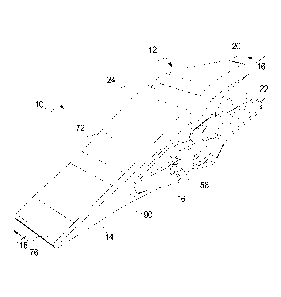
Figs. 3 and 4 illustrate an embodiment of a tooth assembly 10 in
accordance with the present disclosure that may be useful with earth moving
implements, and have particular use in top-wearing applications. The tooth
assembly 10 may be used on multiple types of ground engaging implements
having base edges 18. The tooth assembly 10 includes an adapter 12 configured
for attachment to a base edge 18 of an implement 1, 6 (Figs. 1 and 2,
respectively), and a tip 14 configured for attachment to the adapter 12. The
tooth
assembly 10 further includes a retention mechanism (not shown) securing the
tip
14 to the adapter 12. The retention mechanisms may utilize aspects of the
adapter 12 and tip 14, such as retention apertures 16 through the sides of the
tip
CA 02851416 2014-04-07
WO 2013/052819
PCT/US2012/058988
-14-
14, but those skilled in the art will understand that many alternative
retention
mechanisms may be implemented in the tooth assemblies 10 according to the
present disclosure, and the tooth assemblies 10 are not limited to any
particular
retention mechanism(s). As shown in Fig. 4, once attached to the adapter 12,
the
tip 14 may extended outwardly from a base edge 18 of the implement 1, 6 for
initial engagement with work material (not shown).
Adapter for Top-Wearing Applications (Figs. 5-9)
An embodiment of the adapter 12 is shown in greater detail in
Figs. 5-9. Referring to Fig. 5, the adapter 12 may include a rear portion 19
having a top strap 20 and a bottom strap 22, an intermediate portion 24, and a
nose 26 disposed at the front or forward position of the adapter 12 as
indicated by
the brackets. The top strap 20 and the bottom strap 22 may define a gap 28
there
between as shown in Fig. 6 for receiving the base edge 18 of the implement 1,
6.
The top strap 20 may have a bottom surface 30 that may face and be disposed
proximate to a top surface 32 of the base edge 18, and the bottom strap 22 may
have a top surface 34 that may face and engage a bottom surface 36 of the base
edge 18.
The adapter 12 may be secured in place on the base edge 18 of the
implement 1, 6 by attaching the top strap 20 and the bottom strap 22 to the
base
edge 18 using any connection method or mechanism known to those skilled in the
art. In one embodiment, the straps 20, 22 and the base edge 18 may have
corresponding apertures (not shown) through which fasteners (not shown) such
as
bolts or rivets may be inserted to hold the adapter 12 in place.
Alternatively, the
top and bottom straps 20, 22 may be welded to the corresponding top and bottom
surfaces 32, 36 of the base edge 18 so that the adapter 12 and the base edge
18 do
not move relative to each other during use. To reduce the impact of the top
and
bottom surface welds on the strength of the metal of the base edge 18, the
straps
20, 22 may be configured with different shapes so as to minimize the overlap
of
the welds formed on the top surface 32 and bottom surface 36 of the base edge
CA 02851416 2014-04-07
WO 2013/052819
PCT/US2012/058988
-15-
18. As seen in Figs. 7 and 8, an outer edge 38 of the top strap 20 may have a
different shape than an outer edge 40 of the bottom strap 22 so that the top
strap
20 may generally be shorter and wider than the bottom strap 22. In addition to
the strength maintenance benefits, the additional length of the bottom strap
22
may also provide additional wear material at the bottom surface 36 of the base
edge 18 of the implement 1, 6. Additionally, the top strap 20 may be thicker
than
the bottom strap 22 to provide more wear material on the top of the adapter 12
where a greater amount of abrasion may occur in top-wearing applications.
Those skilled in the art will understand that other connection
configurations for the adapter 12 may be provided as alternatives to the top
and
bottom straps 20, 22 illustrated and described above. For example, the rear
portion of the adapter 12 may be provided with a single top strap 20 and no
bottom strap 22, with the top strap 20 being attached to the top surface 32 of
the
base edge 18. Conversely, a single bottom strap 22 and no top strap 20 may be
provided, with the bottom strap 22 being attached to the bottom surface 36 of
the
base edge 18. As a further alternative, a single center strap may be provided
on
the rear portion of the adapter 12, with the center strap being inserted into
a gap
in the base edge 18 of the implement 1, 6. Further alternative adapter
attachment
configurations will be apparent to those skilled in the art, and are
contemplated
by the inventor as having use in tooth assemblies in accordance with the
present
disclosure.
Returning to Fig. 5, the intermediate portion 24 of the adapter 12
provides a transition between the straps 20, 22 and the nose 26 extending
outwardly from the front end of the adapter 12. The nose 26 is configured to
be
received by a corresponding nose cavity 120 (Fig. 16) of the tip 14 as will be
described more fully below. As shown in Figs. 5 and 6, the nose 26 may have a
bottom surface 42, a top surface 44, opposing side surfaces 46, 48, and a
front
surface 50. The bottom surface 42 may be generally planar and inclined
upwardly relative to the top surface 34 of the bottom strap 22 and,
CA 02851416 2014-04-07
WO 2013/052819
PCT/US2012/058988
-16-
correspondingly, the bottom surface 36 of the base edge 18. An angle of
incline
6 of the bottom surface 42 may be approximately 5 with respect to a
substantially longitudinal axis "A" defined by a major base edge-engaging
surface of one of the straps 20, 22 of the adapter 12, such as the top surface
34 of
the bottom strap 22, as shown. Depending on the implementation, the angle 6 of
the bottom surface 42 may be increased by an additional 1 -3 to facilitate
the
removal of the adapter 12 from a mold or die in which the adapter 12 is
fabricated, and the mating of the nose 26 within the nose cavity 120 (Fig. 16)
of
the tip 14.
The top surface 44 of the nose 26 may be configured to support
the tip 14 during use of the implement 1, 6, and to facilitate retention of
the tip 14
on the nose 26 when bearing the load of the work material. The top surface 44
may include a first support surface 52 disposed proximate the front surface
50, an
intermediate sloped surface 54 extending rearwardly from the first support
surface 52 toward the intermediate portion 24, and the second support surface
56
located between the intermediate surface 54 and the intersection with the
intermediate portion 24 of the adapter 12. Each of the surfaces 52, 54, 56 may
have a generally planar configuration, but may be oriented at angles with
respect
to each other. In the illustrated embodiment, the first support surface 52 may
be
approximately parallel to the bottom surface 42, and may have a draft angle
with
respect to the bottom surface 42 to facilitate removal from a mold or die. The
second support surface 56 may also be oriented approximately parallel to the
bottom surface 42 and the first support surface 52. Further, relative to the
longitudinal axis "A", the second support surface 56 may be disposed at a
higher
elevation on the adapter 12 than the first support surface 52. The
intermediate
surface 54 extends between a rear edge 52a of the first support surface 52 and
a
forward edge 56a of the second support surface 56, with the distance between
the
intermediate surface 54 and the bottom surface 42 increasing as the
intermediate
surface 54 approaches the second support surface 56. In one embodiment, the
CA 02851416 2014-04-07
WO 2013/052819
PCT/US2012/058988
-17-
intermediate surface 54 may be oriented at an angle a of approximately 30
with
respect to the bottom surface 42 of the nose 26, the first support surface 52,
and
the second support surface 56. The slope of the intermediate surface 54
facilitates insertion of the nose 26 into the nose cavity 120 (Fig. 16) of the
tip 14,
while the breadth of the intermediate surface 54 limits the twisting of the
tip 14
once the tip 14 is installed on the nose 26. The first and second support
surfaces
52, 56 also assist in maintaining the orientation of the tip 14 on the adapter
12 as
will be discussed more fully below.
The side surfaces 46, 48 of the nose 26 may be generally planar
and extend upwardly between the bottom surface 42 and the top surface 44. A
pair of projections 58, one on each of the side surfaces 46, 48(only one shown
in
Fig. 6), are substantially coaxially oriented along an axis "B". The axis "B"
is
approximately perpendicular to the longitudinal axis "A". The projections 58
function as part of a retention mechanism (not shown) for holding the tip 14
on
the nose 26. The projections 58 may be positioned to align with the
corresponding apertures 16 (Fig. 3) of the tip 14. The side surfaces 46, 48
may
be approximately parallel or angled inwardly at a longitudinal taper angle
"LTA"
of approximately 3 with respect to the axis "A" (shown in Fig. 7 with respect
to
a line parallel to the axis "A" for clarity) as they extend forward from the
intermediate portion 24 toward the front surface 50 the nose 26, such that the
nose 26 is tapered as shown in Figs. 7 and 8. As best seen in the cross-
sectional
view of Fig. 9, the side surfaces 46, 48 may be angled so that the distance
between the side surfaces 46, 48 decreases substantially symmetrically at
vertical
taper angles "VTA" of approximately 6 with respect to parallel vertical lines
"VL" oriented perpendicular to the axes "A" and "B" as the side surfaces 46,
48
extend downwardly from the top surface 44 toward the bottom surface 42.
Configured in this way, and as shown in cross-section in Fig. 9, the nose 26
may
have a substantially keystone-shaped contour 62 defined by the bottom surface
42, top surface 44 and side surfaces 44, 46 wherein the nose 26 has a greater
CA 02851416 2014-04-07
WO 2013/052819
PCT/US2012/058988
-18-
amount of material proximate the top surface 44 than proximate the bottom
surface 42. This contour 62 may be complementary to contours 93, 131 (Fig. 17)
of the tip 14 which may provide additional wear material at the top of the
tooth
assembly 10 where a greater amount of abrasion occurs in top-wearing
applications, and may reduce drag as the tip 14 is pulled through the work
material as discussed further below.
The front surface 50 of the nose 26 may be planar as shown in Fig.
6, or may include a degree of curvature. As shown in the illustrated
embodiment,
the front surface 50 may be generally planar, and may be angled away from the
intermediate portion 24 as it extends upwardly from the bottom surface 42. In
one embodiment, the front surface 50 may extend forward at an angle 7 of
approximately 15 with respect to a line 50a perpendicular to the bottom
surface
42. With the front surface 50 angled as shown, a reference line 60 extending
inwardly approximately perpendicular to the front surface 50 and substantially
bisecting the projections 58 would create angles pi, 132, each measuring
approximately 15 between the bottom surface 42 and the reference line 60, and
also between the intermediate surface 54 of the top surface 44 and the
reference
line 60. The reference line 60 may also approximately pass through a point of
intersection 60a of lines 60b, 60c that are extensions of the bottom surface
42 and
intermediate surface 54, respectively. Using the bottom surface 42 as a base
reference, the reference line 60 is oriented at angle 131 with respect to the
bottom
surface 42 and bisects the projections 58, the intermediate surface 54 is
oriented
at angle 132 with respect to the reference line 60, and the front surface 50
is
approximately perpendicular to the reference line 60. In alternate
embodiments,
the angle 131 may be approximately 16 to provide approximately 1 of draft
angle
to facilitate removal from a mold or die during fabrication. Similarly, the
angle a
may be approximately 29 to provide approximately 1 of draft angle.
General Duty Tip for Top-Wearing Applications (Figs. 10-17)
CA 02851416 2014-04-07
WO 2013/052819
PCT/US2012/058988
-19-
The tip 14 of the tooth assembly 10 is shown in greater detail in
Figs. 10-17. Referring to Figs. 10 and 11, the tip 14 may be generally wedge-
shaped, and may include a rear edge 70 having a top outer surface 72 extending
forward from a top edge 70a of the rear edge 70, and a bottom outer surface 74
extending forward from a bottom edge 70b of the rear edge 70. The top outer
surface 72 may be angled downwardly, and the bottom outer surface 74 may
extend generally perpendicular to the rear edge 70 such that the top outer
surface
72 and the bottom outer surface 74 converge at a front edge 76 at the front of
the
tip 14. The top outer surface 72 may present a generally planar surface of the
tip
14, but may have distinct portions that may be slightly angled with respect to
each other. Consequently, the top outer surface 72 may include a rear portion
78
extending from the rear edge 70 to a first top transition area 80 at a first
downward angle "FDA" of approximately 29 with respect to a line
perpendicular to a plane "P" defined by the rear edge 70, a front portion 82
extending forward from the transition area 80 at a second downward angle
"SDA" of approximately 25 with respect to a line perpendicular to the plane
"P,", and a tip portion 84 extending from a second tip transition area 82a
between
the front portion 82 and the tip portion 84 at a third downward angle "TDA" of
approximately 27 relative to a line perpendicular to the plane "P". The
generally
planar configuration of the top outer surface 72 may allow work material to
slide
up the top outer surface 72 and toward the base edge 18 of the implement 1, 6
when the front edge 76 digs into a pile of work material with less resistance
to the
forward motion of the implement 1, 6 than may be provided if the tooth
assembly
had a top outer surface with a greater amount of curvature or with one or more
recesses redirecting the flow of the work material.
The bottom outer surface 74 may also be generally planar but with
an intermediate orientation change at a bottom transition area 80a on the
bottom
outer surface 74. Consequently, a rear portion 86 of the bottom outer surface
74
may extend from the rear edge 70 in approximately perpendicular relation to
the
CA 02851416 2014-04-07
WO 2013/052819
PCT/US2012/058988
-20-
plane "P" defined by the rear edge 70 toward the transition area 80a until the
bottom outer surface 74 transitions to a downward angle at a lower front
portion
88. The front portion 88 may be oriented at an angle 0 of approximately 3 -5
with respect to the rear portion 86, depending on the sizing of the tooth
assembly
10, and may extend to the front edge 76 at an elevation below the rear portion
86
by a distance d1. By lowering the front portion 88 of the bottom outer surface
74,
some of the flow and drag relief benefits discussed below that are provided by
the
substantially keystone-shaped contour of the tip 14 may be realized when the
base edge 18 of the implement 1, 6 moves the front edge 76 forward through the
work material.
The tip 14 also includes lateral outer surfaces 90, 92 extending
between the top outer surface 72 and the bottom outer surface 74 on either
side of
the tip 14. Each of the lateral outer surfaces 90, 92 may have a corresponding
one of the retention apertures 16 extending therethrough in a location between
the
rear portions 78, 86. As best seen in the bottom view of Fig. 13 the front
view of
Fig. 14, and the cross-sectional view of Fig. 15, the lateral outer surfaces
90, 92
may be angled so that the distance between the lateral outer surfaces 90, 92
decreases as the lateral outer surfaces 90, 92 extend downwardly from the top
outer surface 72 toward the bottom outer surface 74. Configured in this way,
the
tip 14 may have a substantially keystone-shaped contour 93 in substantial
correspondence to the substantially keystone-shaped contour 62 described above
for the nose 26.
The tip 14 is provided with a greater amount of wear material
proximate the top outer surface 72 where a greater amount of abrasion may
occur,
and a lesser amount of wear material proximate the bottom outer surface 74
where less abrasion may occur in top-wearing applications. In this
configuration,
the amount of wear material, and correspondingly the weight and cost of the
tip
14, may be reduced or at least be more efficiently distributed, without
reducing
the useful life of the tooth assembly 10. The tapering of the lateral outer
surfaces
CA 02851416 2014-04-07
WO 2013/052819
PCT/US2012/058988
-21-
90, 92 from top to bottom to produce the substantially keystone-shaped contour
93 of the tip 14 may reduce the amount of drag experienced by the tip 14 as it
is
pulled through the work material. As the top outer surface 74 is pulled
through
the work material, the work material flows over the top outer surface 74
outwardly and around the tip 14 as indicated by the arrows "FL" in Fig. 15,
with
less engagement of the lateral outer surfaces 90, 92 than if the lateral outer
surfaces 90, 92 were parallel and maintained a constant width as they extend
downwardly from the top outer surface 74.
Figs. 12-15 further illustrate that the tip 14 may be configured to
taper as the lateral outer surfaces 90, 92 extend from the rear edge 70 toward
the
front edge 76, with the lateral outer surfaces having an intermediate change
in the
taper of the lateral outer surfaces 90, 92. The lateral outer surfaces 90, 92
may
have rear portions 94, 96 extending forward from the rear edge 70 toward the
front edge 76 and oriented such that the distance between the rear portions
94, 96
decreases as the rear portions 94, 96 approach a side transition area 97 with
a side
taper angle "STA" of approximately 30 with respect to a line perpendicular to
the
plane "P". It should be noted that the side taper angle "STA" is approximately
equal to the longitudinal taper angle "LTA" of the nose 26 of the adapter 12.
Beyond the transition area 80, the lateral outer surfaces 90, 92 transition to
front
portions 98, 100 that that may be approximately parallel or converge at a
shallower angle relative to a major longitudinal axis "D" defined by the tip
14 as
the front portions 98, 100 progress forward to the front edge 76. The
reduction in
the tapering of the front portions 98, 100 of the lateral outer surfaces 90,
92
behind the front edge 76 may preserve wear material proximate the front edge
76
the front of the tip 14 where the amount of abrasion experienced by the tip 14
is
greater than at the area proximate the rear edge 70of the tip 14.
As shown in Fig. 13, the front portion 88 of the bottom outer
surface 74 may include a relief 102. The relief 102 may extend upwardly from
the bottom outer surface 74 into the body of the tip 14 to define a pocket "P"
in
CA 02851416 2014-04-07
WO 2013/052819
PCT/US2012/058988
-22-
the tip 14. The cross-sectional view of Fig. 16 illustrates the geometric
configuration of one embodiment of the relief 102. The relief 102 may include
an
upward curved portion 104 extending upwardly into the body of the tip 14
proximate the front edge 76. Looking at the relief 102 as it extends from
proximate the front edge 76 toward the rear edge 70, as the curved portion 104
of
the relief 102 extends upwardly, the relief 102 transitions into a tapered
portion
106. The tapered portion 106 may extend downward as it extends rearward
toward the rear edge 70, and ultimately terminate at the transition area 80
and the
rear portion 86 of the bottom outer surface 74. The illustrated configuration
of
the relief 102 reduces the weight of the tip 14, reduces resistance of the
movement of the tip 14 through the work material, and provides a self-
sharpening
feature to the tip 14 as will be described more fully below. However,
alternative
configurations for the relief 102 that would provide benefits to the tip 14
will be
apparent to those skilled in the art and are contemplated by the inventors as
being
within the scope of tooth assemblies 10 that are in accordance with the
present
disclosure.
The tip 14 may be configured to be received onto the nose 26 of
the adapter 12. In the rear view of the tip 14 in Fig. 17, a nose cavity 120
may be
defined within the tip 14. The nose cavity 120 may have a complementary
configuration relative to the nose 26 of the adapter 12, and may include a
bottom
inner surface 122, a top inner surface 124, a pair of opposing side inner
surfaces
126, 128, and a front inner surface 130. As seen from behind, the nose cavity
120 may have a substantially keystone-shaped contour 131 in a manner
complementary to the contour 93 of the exterior of the tip 14 and the contour
62
of the nose 26 of the adapter 12. The distances between the top outer surface
72
and top inner surface 124, and between the bottom outer surface 74 and bottom
inner surface 122, may be constant in the lateral direction across the tip 14.
The
side inner surfaces 126, 128 may be angled inwardly so that the distance
between
the side inner surfaces 126, 128 decreases as the side inner surfaces 126, 128
CA 02851416 2014-04-07
WO 2013/052819
PCT/US2012/058988
-23-
extend downwardly from the top inner surface 124 toward the bottom inner
surface 122. Oriented in this way, the side inner surfaces 126, 128 mirror the
lateral outer surfaces 90, 92 and a constant thickness is maintained between
the
side inner surfaces 126, 128 of the nose cavity 120 and the lateral outer
surfaces
90, 92, respectively, on the exterior of the tip 14. Fig. 17 further
illustrates that
the nose cavity 120 may include recesses 140 in the side inner surfaces 126,
128
that may be configured to receive the projections 58 of the nose 26 of the
adapter
12 when the nose 26 is inserted into nose cavity 120. Once received, the
retention mechanism (not shown) of the tooth assembly 10 may engage the
projections 58 to secure the tip 14 on the adapter 12.
The cross-sectional view of Fig. 16 illustrates the correspondence
between the nose cavity 120 of the tip 14 and the nose 26 of the adapter 12 as
shown in Fig. 6. The bottom inner surface 122 may be generally planar and
approximately perpendicular to the rear edge 70. The bottom inner surface 122
may also be generally parallel to the rear portion 86 of the bottom outer
surface
74. If the bottom surface 42 of the adapter 12 has an upward draft angle, the
bottom inner surface 122 of the tip 14 may have a corresponding upward slope
to
match the draft angle.
The top inner surface 124 may be shaped to mate with the top
surface 44 of the nose 26, and may include a first support portion 132, a
sloped
intermediate portion 134, and a second support portion 136. The first and
second
support portions 132, 136 may be generally planar and approximately parallel
to
the bottom inner surface 122, but may have a slight downward slope
corresponding to the orientation that may be provided in the first and second
support surfaces 52, 56 of the top surface 44 of the nose 26 to facilitate
removal
from a mold or die. The intermediate portion 134 of the top inner surface 124
may extend between a rear edge 132a of the first support portion 132 and a
forward edge 136a of the second support portion 136, with the distance between
the intermediate portion 134 and the bottom inner surface 122 increasing in a
CA 02851416 2014-04-07
WO 2013/052819
PCT/US2012/058988
-24-
similar manner as between the intermediate surface 54 and the bottom surface
42
of the nose 26 of the adapter 12. Consistent with the relationship between the
bottom surface 42 and intermediate surface 54 of the nose 26 of the adapter
12,
the intermediate portion 134 of the nose cavity 120 of the tip 12 may be
oriented
at an angle a of approximately 30 with respect to the bottom inner surface
122
and the first and second support portions 132, 136.
The front inner surface 130 of the nose cavity 120 has a shape
corresponding to the front surface 50 of the nose 26, and may be planar as
shown
or have the necessary shape to be complementary to the shape of the front
surface
50. As shown in Fig. 16, the front inner surface 130 may be angled toward the
front edge 76 at an angle y of approximately 15 with respect to a line 130a
perpendicular to the bottom inner surface 122. A reference line 138 may extend
inwardly substantially perpendicular to the front inner surface 130 and
substantially bisect the retention aperture 16. To match the shape of the nose
26,
the reference line 138 may be oriented at an angle 131 of approximately 150
with
respect to the bottom inner surface 122 of the nose cavity 120, and at an
angle [32
of approximately 15 with respect to the intermediate portion 134 of the top
inner
surface 124. The shapes of the nose 26 and nose cavity 120 are exemplary of
one
embodiment of the tooth assembly 10 in accordance with the present disclosure.
Those skilled in the art will understand that variations in the relative
angles and
distances between the various surfaces of the nose 26 and nose cavity 120 may
be
varied from the illustrated embodiment while still producing a nose and nose
cavity having complementary shapes, and such variations are contemplated by
the inventors as having use in tooth assemblies 10 in accordance with the
present
disclosure.
Penetration Tip for Top-Wearing Applications (Figs. 18-22)
Where the tooth assemblies 10 are being used in rocky
environments where a greater ability to penetrate the work material may be
required, it may facilitate excavation by providing a tip having a sharper
CA 02851416 2014-04-07
WO 2013/052819
PCT/US2012/058988
-25-
penetration end for breaking up the work material. Referring to Figs. 18-22, a
penetration tip 150 is illustrated wherein surfaces and other elements of the
tip
150 that are similar or correspond to elements of the tip 14 are identified by
the
same reference numerals, and may include a rear edge 70, a top outer surface
72
and a bottom outer surface 74, with the top outer surface 72 and bottom outer
surface 74 extending forward from the rear edge 70 and converging to a front
edge 76. Lateral outer surfaces 90, 92 may include retention apertures 16 as
described above. The top outer surface 74 may have a rear portion 78 and a
front
portion 82, and the bottom outer surface 76 having a rear portion 86 and a
front
portion 88. As with the tip 14, the rear portion 86 of the bottom outer
surface 74
may be approximately perpendicular to the rear edge 70 and approximately
parallel to the bottom inner surface 122 of the nose cavity 120 (Figs. 21 and
22).
The front portion 88 may be oriented at angle 0 in the range of 8 -10 , and
may
be approximately 9', with respect to the rear portion 86, depending on the
sizing
of the tooth assembly 10, and may extend to the front edge 76 at an elevation
below the rear portion 86 by a distance d2. The sizing of the tip assembly 10
may
also determine whether the tip outer surface 72 includes a hook 152 extending
therefrom that may be used to lift and position the tip 150 during
installation.
The rear portions 78, 86 may extend forward from the rear edge 70
with the rear portions 94, 96 of the lateral outer surfaces 90, 92 being
tapered and
converging as the lateral outer surfaces 90, 92 extend from the rear edge 70
at the
side taper angle "STA" of approximately 3 . As the rear portions 78, 86
approach the front edge 76, the top and bottom outer surfaces 72, 74 may
transition into the front portions 82, 88. The lateral outer surfaces 90, 92
may
transition into the front portions 98, 100 that may initially be approximately
parallel and then further transition as the front portions 98, 100 approach
the front
edge 76 to having a greater taper at a penetration taper angle "PTA" of
approximately 20 with respect to a line perpendicular to the plane "P" to
converge at a greater rate than the convergence within the rear portions 94,
96.
CA 02851416 2014-04-07
WO 2013/052819
PCT/US2012/058988
-26-
Consequently, the front edge 76 may be narrower in relation to the general
width
of the penetration tip 150 as best seen in Fig. 19 than in the embodiment of
the tip
14 as shown in Fig. 12. The narrow front edge 76 of the tip 150 may provide a
smaller surface area for engaging the rocky work material, but increase the
force
per unit of contact area applied to the rocky work material by the series of
tooth
assemblies 10 attached at the base edge 18 of the implement 1, 6 to break up
the
rocky work material.
In addition to narrowing the width of the front edge 76 of the tip
150, the ability of the tip 150 to penetrate rocky work material as wear
material
wears away from the tip 150 over time may be further enhanced by reducing the
overall vertical thickness of the tip 150. In the illustrated embodiment,
reliefs
154, 156 may be provided on either side of the front portion 82 of the top
outer
surface 72, and reliefs 158, 160 may be provided on either side of the front
portion 88 of the bottom outer surface 74. The reliefs 154, 156, 158, 160 may
extend rearwardly from the front edge 76 and tip portion 84. As wear material
wears away from the front 76 of the tip 150 toward the rear edge 70 of the tip
14
over time, a thickness T of the remaining work material-engaging surface of
the
tip 150 may initially increase as the material of the tip portion 84 wears
away.
When the wear material wears away and the work material-engaging surface
reaches the reliefs 154, the thickness T may remain relatively constant with
the
exception of the areas of the front portions 82, 88 between the reliefs 154,
156,
158, 160 where the thickness will gradually increase as the wear material
continues to wear away in the direction of the rear portions 78, 86.
Adapter for Bottom-Wearing Applications (Figs. 23-25)
As mentioned above, bottom-wearing applications may involve
differing operating conditions than top-wearing applications and,
consequently,
may present differing design requirements for the adapters and tips of tooth
assemblies that may result in more efficient digging and loading of the work
material. For example, it may be desirable to align bottom surfaces of bottom-
CA 02851416 2014-04-07
WO 2013/052819
PCT/US2012/058988
-27-
wearing tips parallel to the ground and parallel to the bottom surface of the
implement 1 to facilitate moving along the ground to collect work material,
whereas it may be desirable for top-wearing tips as described above to more
closely extend the shape of the implement 6 to facilitate scooping work
material
into the bucket 7 of the implement 6. The differing design requirements may
lead
to differences in the designs of both the adapters and the tips of the tooth
assemblies.
Figs. 23-25 illustrate an embodiment of an adapter 170 of tooth
assembly 10 in accordance with the present disclosure that may have particular
use on an implement 1 for a bottom-wearing application as well as other types
of
ground engaging implements 1, 6 having base edges 18. The surfaces and other
elements of the adapter 170 that are similar or correspond to elements of the
adapter 12 as described above are identified by the same reference numerals.
Referring to Figs. 23 and 25, the adapter 170 may include a top strap 20, a
bottom
strap 22, an intermediate portion 24, and a nose 26, with the top strap 20 and
the
bottom strap 22 defining a gap 28 therebetween for receiving the base edge 18
of
the implement 1, 6. The top strap 20 may have a bottom surface 30 that may
face
and be disposed proximate to a top surface 32 of the base edge 18, and the
bottom
strap 22 may have a top surface 34 that may face and engage a bottom surface
36
of the base edge 18. Depending on the size of the application and,
correspondingly, the tooth assembly 10, the adapter 170 may include a hook 172
extending upwardly from the top strap 20 for attachment of a lifting device
(not
shown) that may be used to lift and position the adapter 170 on the base edge
18
during installation. The adapter 12 as described above may similarly be
provided
with hook 172 if necessary in larger applications.
The straps 20, 22 of the adapter 170 may be configured similar to
the adapter 12 with different shapes so as to minimize the overlap of the
welds
formed on the top surface 32 and bottom surface 36 of the base edge 18. In
bottom-wearing applications, though, it may be desirable to make the top strap
20
CA 02851416 2014-04-07
WO 2013/052819
PCT/US2012/058988
-28-
longer than the bottom strap 22, and to make the bottom strap 22 thicker than
the
top strap 20 to provide additional wear material on the bottom of the adapter
170
where additional abrasion may occur as the adapter scrapes along the ground in
bottom-wearing applications.
The nose 26 may also have the same general configuration as the
nose 26 of the adapter 12 and be configured to be received by corresponding
nose
cavities 120 of tips that will be described more fully below. The nose 26 may
have a bottom surface 42, a top surface 44, opposing side surfaces 46, 48, and
a
front surface 50, with the top surface 44 having first and second support
surfaces
52, 56 and intermediate surface 54 extending therebetween. The side surfaces
46,
48 of the nose 26 may be generally planar and extend vertically between the
bottom surface 42 and the top surface 44 as best seen in Fig. 25, and may be
approximately parallel or angled inwardly as they extend from the intermediate
portion 24 so that the nose 26 is tapered from rear to front. The side
surfaces 46,
48 may be angled so that the distance between the side surfaces 46, 48
decreases
as the side surfaces 46, 48 extend downwardly from the top surface 44 toward
the
bottom surface 42 due to the vertical taper angle "VTA" to define a
substantially
keystone-shaped contour 174 similar to those described above. The
substantially
keystone-shaped contour 174 of the adapter 170 may be complementary to the
contours of the tips described below.
Relative to the nose 26 of the adapter 12 for top-wearing
applications, the nose 26 of the adapter 170 may be oriented downwardly with
respect to the straps 20, 22 to make the angle 6 (top-wearing version shown in
Fig. 4) approximately 0 . At this orientation, the bottom surface 42 may be
generally planar and approximately parallel to the top surface 34 of the
bottom
strap 22 and, correspondingly, the bottom surface 36 of the implement 1, 6.
Further, relative to the substantially longitudinal axis "A," the bottom
surface 42
may be disposed lower on the adapter 12 than the top surface 34 of the bottom
strap 22. The remaining relative positioning of the surfaces of the adapter 12
CA 02851416 2014-04-07
WO 2013/052819
PCT/US2012/058988
-29-
may be maintained. Consequently, using the bottom surface 42 as a base
reference, the reference line 60 is oriented at angle 131 with respect to the
bottom
surface 42 and bisects the projections 58, the intermediate surface is
oriented at
angle P2 with respect to the reference line 60, and the front surface 50 is
approximately perpendicular to the reference line 60. The angles pi, P2 may
each
be approximately 15 , the intermediate surface 54 may be oriented at an angle
a
of approximately 30 with respect to the bottom surface 42 of the nose 26, the
top
surface 34 of the bottom strap 22, and the first and second support surfaces
52,
56, and the front surface 50 may extend forward at an angle 7 of approximately
15 with respect to a line 50a perpendicular to the bottom surface 42 or top
surface 34 of the bottom strap 22. The orientation of the nose 26 of the
adapter
12 with respect to the straps 20, 22 coupled with the configurations of the
tips
described below may align the bottom outer surfaces of the tips approximately
parallel to the bottom of the implementl, 6 and the ground in order to enable
the
overall bottom of the tooth assembly 10 to slide along the surface of the
ground
and into the work material to load the implement 1, 6.
General Duty Tip for Bottom-Wearing Applications (Figs. 26-30)
In addition to the adapter 170, tips of the tooth assembly 10 may
be configured for improved performance in bottom-wearing applications. One
example of a general duty tip 180 for use with the adapter 170 is shown in
greater
detail in Figs. 26-30 where similar surfaces and components as previously
discussed with respect to tip 14 are identified by the same reference
numerals.
Referring to Figs. 26 and 27, the tip 180 may be generally wedge-shaped with
top
and bottom outer surfaces 72, 74 extending forward from a top and bottom edges
70a, 70b, respectively, of the rear edge 70 and converging at front edge 76.
The
top outer surface 72 may be angled downwardly similar to the tip 14, and the
rear
portion 78 may have a first downward angle "FDA" of approximately 29 , the
front portion 82 may have a second downward angle "SDA" of approximately
25 , and the tip portion 84 may have a third downward angle "TDA" of
CA 02851416 2014-04-07
WO 2013/052819
PCT/US2012/058988
-30-
approximately 27 . The generally planar configuration of the top outer surface
72 may allow the work material to slide up the top outer surface 72 and into
the
bucket (not shown) of the machine (not shown) when the front edge 76 digs into
a pile of work material. As best seen in Fig. 28, the lateral outer surfaces
90, 92
may be angled so that the distance between the lateral outer surfaces 90, 92
decreases as the lateral outer surfaces 90, 92 extend downwardly from the top
outer surface 72 toward the bottom outer surface 74 at vertical taper angles
"VTA" of approximately 3 to define a substantially keystone-shaped contour
188 complimentary to the contour 174 described above for the nose 26 of the
adapter 170
The bottom outer surface 74 may also be generally planar but with
an intermediate elevation change at transition area 80a. The rear portion 86
of
the bottom outer surface 74 may extend forward approximately perpendicular to
the rear edge 70 to the transition area 80 where the bottom outer surface 74
transitions to lower front portion 88. Front portion 88 may also be oriented
approximately perpendicular to the rear edge 70, and may extend to the front
edge 76 at an elevation below the rear portion 86 by a distance d3. When the
tooth
assembly 10 of an implement 1, 6 digs into the work material, a majority of
the
abrasion between the tip 180 and the work material occurs at the front edge
76,
tip portion 84 of the top outer surface, and the front portion 88 of the
bottom
outer surface 74 of the tip 14. By lowering the front portion 88 of the bottom
outer surface 74, additional wear material is provided at the high abrasion
area to
extend the useful life of the tooth assembly 10.
The top outer surface 72 of the tip 180 may include a relief 182
extending across the front portion 82 and adjacent parts of the rear portion
78 and
tip portion 84. As seen in Figs. 28-30, the relief 182 may extend downwardly
from the top outer surface 72 into the body of the tip 180 to define a pocket
in the
tip 180. The cross-sectional view of Fig. 30 illustrates the geometric
configuration of one embodiment of the relief 182. The relief 182 may include
a
CA 02851416 2014-04-07
WO 2013/052819
PCT/US2012/058988
-31-
downward curved portion 184 extending downwardly into the body of the tip 180
proximate the tip portion 84 and the front edge 76. As the curved portion 184
extends downwardly, the relief 182 may turn rearward toward the rear edge 70
and transition into a rearward tapered portion 186. The tapered portion 186
may
extend upward as it extends rearward toward the rear edge 70, and ultimately
intersect with the transition area 80 and the rear portion 78 of the top outer
surface 72. The illustrated configuration of the relief 182 reduces the weight
of
the tip 180, reduces resistance of the movement of the tip 180 through the
work
material, and provides a self-sharpening feature to the tip 180 as will be
described
more fully below. However, alternative configurations for the relief 182
providing benefits to the tip 180 will be apparent to those skilled in the art
and
are contemplated by the inventors as having use in tooth assemblies 10 in
accordance with the present disclosure.
The tip 180 may be configured to be received onto the nose 26 of
the adapter 170 by providing the nose cavity 120 with a complementary
configuration relative to the nose 26 of the adapter 170 similar to the nose
cavity
120 of the tip 14, including a keystone-shaped contour that is complementary
to
the contour of the exterior of the adapter 170. The cross-sectional view of
Fig. 30
illustrates the correspondence between the nose cavity 120 of the tip 180 and
the
nose 26 of the adapter 170. The bottom inner surface 122 may be generally
planar and approximately perpendicular to the rear edge 70, and may also be
generally parallel to the rear portion 86 and front portion 88 of the bottom
outer
surface 74 to orient the bottom outer surface 74 approximately parallel to the
base
edge 18 of the implement 1, 6 when the tip 180 is assembled on the adapter
170.
In other respects, the top inner surface 124, side inner surfaces 126, 128 and
front
inner surface 130 may have complementary shapes to the corresponding surfaces
of the nose 26 so that the surfaces face and engage when the tip 180 is
assembled
on the adapter 170.
CA 02851416 2014-04-07
WO 2013/052819
PCT/US2012/058988
-32-
Abrasion Tip for Bottom-Wearing Applications (Figs. 31-36)
Depending on the particular earth moving environment in which
the tooth assemblies 10 are being used, the tip 180 of the tooth assembly 10
as
illustrated and described above with respect to Figs. 26-30 may be modified as
necessary. For example, where the machine may be operating on work materials
that are highly abrasive and may wear down tips at a much greater rate, it may
be
desirable to provide more wear material at the front and on the bottom of the
tip.
Figs. 31-36 illustrate one embodiment of a tip 190 having use in loading
abrasive
work materials. The tip 190 may have the same general wedge-shaped
configuration as discussed above for the tip 180 with the top and bottom outer
surfaces 72, 74 extending forward from the rear edge 70 and converging to the
front edge 76 as shown in Figs. 31 and 32. To reduce weight in lower wear
areas
and to provide a measure of self-sharpening performance, the front portion 82
of
the tip outer surface 72 may be provided with reliefs 192, 194 on either side
(Figs. 33 and 34). The reliefs 192, 194 may extend rearwardly proximate the
tip
portion 84. As wear material wears away from the front of the tip 190 over
time,
the height of the material-engaging surface of the tip 150 proximate the outer
edges of the front portion 82 of the top outer surface 72 may remain
relatively
constant. To further reduce the weight of the tip 190, a further relief 196
may be
provided in the bottom outer surface 74. The relief 196 may extend upwardly
into the body of the tip 190, and may be disposed further rearward than the
top
reliefs 192, 194 so as not to remove too much wear material from the high
abrasion areas at the proximate the front edge 76.
To compensate for the greater abrasion experienced by the tip 190,
the bottom outer surface 74 may be widened to provide additional wear
material.
As best seen in Figs. 33 and 35, the upper portion of the tip 190 has a
similar
keystone-shaped contour as the tips discussed above that is complimentary to
the
contour of the adapter nose 26. Proximate the intersection of the lateral
outer
surfaces 90, 92 with the bottom outer surface 74, side flanges 198, 200 extend
CA 02851416 2014-04-07
WO 2013/052819
PCT/US2012/058988
-33-
laterally from the lateral outer surfaces 90, 92, respectively, to widen the
bottom
outer surface 74. The side flanges 198, 200 may extend the entire length of
the
tip 190 from the rear edge 70 to the front edge 76. Top flange surfaces 202,
204
may extend forward approximately perpendicular to the rear edge 70 of the tip
190, and the bottom outer surface 74 is also a bottom flange surface, and may
be
angled downwardly relative to the top flange surfaces 202, 204 at the angle 0
in
the range of 1 -3 , and may be approximately 2 . More specifically, the angle
0 is
between the bottom outer surface 74 and a line approximately perpendicular to
the rear edge 70 and approximately parallel to the top flange surfaces 202,
204 as
shown in Figs. 32 and 35. With this configuration, the distance between the
bottom outer surface 74 and the top flange surfaces 202, 204 may increase as
the
side flanges 198, 200 extend forward from the rear edge 70 toward the front
edge
76 until the top flange surfaces 202, 204 intersect the tip portion 84 of the
top
outer surface 72, which in turn is converging with the bottom outer surface 74
toward the front edge 76. With this arrangement, the side flanges 198, 200
provide additional wear material at the front and bottom of the tip 190 where
maximum abrasion may occur. With further reference to Fig. 36, the nose cavity
120 as illustrated is similar in configuration to the nose cavities 120 as
described
above and complimentary to the nose 26 of the adapter 170, with the bottom
inner surface 122 being approximately perpendicular to the rear edge 70.
Penetration Tip for Bottom-Wearing Applications (Figs. 37-41)
Where the tooth assemblies 10 are being used in rocky
environments where a greater ability to penetrate the work material may be
required, it may be required to provide the tip having a sharper penetration
end
for breaking up the work material. Referring to Figs. 37-41, a penetration tip
210
is illustrated with the top outer surface 72 and bottom outer surface 74
extending
forward from the rear edge 70 and converging to the front edge 76. The top
outer
surface 72 may include reliefs 212, 214 on either side of the front portion 82
similar to the reliefs 192, 194 described above. The rear portion 78 of the
top
CA 02851416 2014-04-07
WO 2013/052819
PCT/US2012/058988
-34-
outer surface 72 may extend forward from the rear edge 70 with the lateral
outer
surfaces 90, 92 being approximately parallel or slightly tapered at a side
taper
angle "STA" of approximately 3 to match the taper of the nose 26 of the
adapter
170 and converging as the lateral outer surfaces 90, 92 extend from the rear
edge
70. As the rear portion 78 approaches the front edge 76, the top outer surface
72
may transition into the front portion 82. The lateral outer surfaces 90, 92
having
a greater taper such that the lateral outer surfaces 90, 92 may transition
into the
front portions 98, 100 that may initially be approximately parallel of have an
intermediate taper angle "ITA" of approximately .8 and then further transition
as
the front portions 98, 100 approach the front edge76 to have a greater taper
at a
penetration taper angle "PTA" of approximately 10 with respect to a line
perpendicular to the plane "P" to converge at a greater rate than the
convergence
within the rear portion 78. Consequently, the front edge 76 may be narrower in
relation to the general width of the penetration tip 210 than in the other
embodiments of the tip 180, 190. The narrow front edge 76 may provide a
smaller surface area for engaging the rocky work material, but increase the
force
per unit of contact area applied to the rocky work material by the series of
tooth
assemblies 10 attached at the base edge 18 of the implement 1, 6 to break up
the
rocky work material.
While wear material may be removed from the penetration tip 210
by narrowing the front edge 76, additional wear material still may be provided
to
the bottom outer surface 74 by angling the bottom outer surface 74 downwardly
as it extends from the rear edge 70 as shown in Figs. 40 and 41. The nose
cavity
120 has the configuration described above with the bottom inner surface 122
extending approximately perpendicular to the rear edge 70 of the tip 210. The
bottom outer surface 74 may be angled downwardly relative to a line
approximately parallel to the bottom inner surface 122 and approximately
perpendicular to the rear edge 70 at angle 0 that is in the range of 6 -8 ,
and may
be approximately 7 .
CA 02851416 2014-04-07
WO 2013/052819
PCT/US2012/058988
-35-
Unitary Tooth for Top-Wearing Applications (Figs. 42-45)
The tooth assemblies discussed above are each comprised of an
adapter and a tip attached thereto. In some applications, it may be desirable
to
attach a unitary component to the implement 1, 6 to, for example, eliminate
the
risk of failure of the retention mechanism attaching a tip to an adapter nose.
To
accommodate such implementations, the various combinations of adapters and
tips set forth above may be configured as unitary components providing
operational benefits described herein. As an example, Figs. 42-45 illustrate
an
integrally formed unitary general duty tooth 270 for top-wearing applications
having characteristics of the adapter 12 and the tip 14. The tooth 270 may
include rear top and bottom straps 272, 274, respectively, and a front tip
portion
276 connected by an intermediate portion 278. The tip portion 276 may include
a
top outer surface 280 and a bottom outer surface 282 extending forward from
the
intermediate portion 278 and converging at a front edge 284. The top and
bottom
outer surfaces 280, 282 may have generally the same geometries as the top and
bottom outer surfaces 72, 74, respectively, of the tip 14, and the bottom
outer
surface 282 may include a relief (not shown). The tip portion 276 may further
include oppositely disposed lateral outer surfaces 286, 288 extending between
the
top outer surface 280 and the bottom outer surface 282.
As best seen in Fig. 43, the lateral outer surfaces 286, 288 may be
angled so that the distance between the lateral outer surfaces 286, 288
increases
as the lateral outer surfaces 286, 288 extend vertically from the bottom outer
surface 282 toward the top outer surface 280. Configured in this way, the tip
portion 276 may have a similar keystone-shaped contour as the tip 14 to
provide
a greater amount of wear material proximate the top surface 280 than proximate
the bottom surface 282 where a greater amount of abrasion and wear occur in
top-
wearing applications. Due to the geometric similarities, the tip portion 276
may
have wear material wear away over time in a similar manner as the tip 14 as
illustrated in Figs. 63-70 and described in the accompanying text.
CA 02851416 2014-04-07
WO 2013/052819
PCT/US2012/058988
-36-
In order for the tooth 270 to be replaceable, the tooth 270 may be
bolted or similarly demountably fastened to the base edge 18 of the implement
1,
6 instead of being welded to the surface. The straps 272, 274 may be
configured
for such attachment to the base edge 18 by providing apertures 290, 292
through
the straps 272, 274, respectively, as seen in Figs. 42, 44 and 45. During
assembly, the apertures 290, 292 may be aligned with corresponding apertures
of
the base edge 18, and appropriate connection hardware may be inserted to
retain
the tooth 270 on the base edge 18 of the implement 1, 6. After the tip portion
276
wears down to the point of requiring replacement, the connection hardware may
be disconnected and the remains of the tooth 270 may be removed and replaced
by a new tooth 270.
Unitary Tooth for Bottom-Wearing Applications (Figs. 46-49)
It may also be desirable in bottom-wearing implementations, such
as loader buckets, to attach a unitary component to the base edge 18 of the
implement 1, 6. Figs. 46-49 illustrate an integrally formed unitary general
duty
tooth 300 for bottom-wearing applications having characteristics of the
adapter
170 and general duty tip 180. The tooth 300 may include rear top and bottom
straps 302, 304, respectively, and a front tip portion 306 connected by an
intermediate portion 308. The tip portion 306 may include a top outer surface
310 and a bottom outer surface 312 extending forward from the intermediate
portion 308 and converging at a front edge 314. The top and bottom outer
surfaces 310, 312 may have generally the same geometries as the top and bottom
outer surfaces 72, 74, respectively, of the tip 180, and the top outer surface
312
may include a relief 316. The tip portion 306 may further include oppositely
disposed lateral outer surfaces 318, 320 extending between the top outer
surface
310 and the bottom outer surface 312. As best seen in Fig. 47, the lateral
outer
surfaces 318, 320 may be angled so that the distance between the lateral outer
surfaces 318, 320 increases as the lateral outer surfaces 318, 320 extend
vertically
from the bottom outer surface 312 toward the top outer surface 310. Due to the
CA 02851416 2014-04-07
WO 2013/052819
PCT/US2012/058988
-37-
geometric similarities, the tip portion 306 may have wear material wear away
over time in a similar manner as the tip 180 as illustrated in Figs. 70-75 and
described in the accompanying text.
In order for the tooth 300 to be replaceable, the tooth 300 may be
bolted or similarly demountably fastened to the base edge 18 of the implement
1,
6 instead of being welded to the surface. The straps 302, 304 may be
configured
for such attachment to the base edge 18 by providing apertures 322, 324
through
the straps 302, 304, respectively, as seen in Figs. 46, 48 and 49. During
assembly, the apertures 322, 324 may be aligned with corresponding apertures
of
the base edge 18, and appropriate connection hardware may be inserted to
retain
the tooth 300 on the base edge 18 of the implement 1, 6. After the tip portion
306
wears down to the point of requiring replacement, the connection hardware may
be disconnected and the remains of the tooth 300 may be removed and replaced
by a new tooth 300.
Industrial Applicability
Tooth assemblies 10 in accordance with the present disclosure
incorporate features that may extend the useful life of the tooth assemblies
10 and
improve the efficiency of the tooth assemblies 10 in penetrating into the work
material. As discussed above, the substantially keystone¨shaped contour 93 of
the tip 14, for example, places a greater amount of wear material towards the
top
of the tip 14 where a greater amount of abrasion occurs in top-wearing
applications. At the same time, wear material is removed from the lower
portion
of the tip 14 where less abrasion occurs, thereby reducing the weight and the
cost
of the tip 14, though in some implementations the top strap 20 may need to be
thicker than dictated by abrasion to provide sufficient strength and help
prevent
breakage due to the loading forces. In bottom-wearing applications, the tips
180,
190, 210 may be provided with additional wear material proximate the bottom of
the tips 180, 190, 210 where a greater amount of wear occurs as the tips 180,
190,
210 scrape along the ground.
CA 02851416 2014-04-07
WO 2013/052819
PCT/US2012/058988
-38-
The design of the tooth assemblies 10 in accordance with the
present disclosure may also reduce the stresses applied to the projections 58
and
the retention mechanism connecting the tips 14, 150, 180, 190, 210 to the
adapters 12, 170. Using the adapter 12 and tip 14 for illustration in Figs. 51
and
52, based on the machining tolerances required in the retention apertures 16,
the
projections 58 and the corresponding components of a retention mechanism (not
shown), the tip 14 may experience movement relative to the adapter 12, and in
particular to the nose 26, during use of the machine. The relative movement
may
cause shear stresses in the components of the retention mechanism as the
adapter
12 and tip 14 move in opposite directions. In prior tooth assemblies where a
nose
of an adapter may have a triangular shape in cross-section, or may have a more
rounded shape than the substantially keystone¨shaped contour 62 of the nose
26,
facing surfaces of the nose of the adapter and the nose cavity of the tip may
separate and allow the tip to rotate about a longitudinal axis of the tooth
assembly
relative to the adapter. The twisting of the tip may cause additional shear
stresses
on the components of the retention mechanism.
In contrast, in the tooth assemblies 10 in accordance with the
present disclosure, the support surfaces 52, 56 of the adapter nose 26 may be
engaged by the corresponding support portions 132, 136 that define the nose
cavity 120. As shown in the cross-sectional view of Fig. 50, when the tip 14
is
installed on the adapter nose 26 and disposed at a maximum engagement
position, the planar surfaces of the nose 26 are engaged by the corresponding
planar portions of the surfaces that define the nose cavity 120 of the tip 14.
Consequently, the bottom surface 42 of the adapter 12 may face and engage the
bottom inner surface 122 of the tip 14, the support surfaces 52, 54, 56 of the
top
surface 44 of the adapter 12 may face and engage the corresponding portions
132,
134,136 of the top inner surface 124 of the tip 14 and the front surface 50 of
the
adapter 12 may face and engage the front inner surface 130 of the tip 14.
Though
not shown, the side surfaces 46, 48 of the nose 26 of the adapter 12 may face
and
CA 02851416 2014-04-07
WO 2013/052819
PCT/US2012/058988
-39-
engage the side inner surfaces 126, 128, respectively, of the nose cavity 120
of
the tip 14. With the surfaces engaging, the tip 14 may remain relatively
stationary with respect to the nose 26 of the adapter 12.
Due to the tolerances within the retention mechanism, the tip 14
may be able to slide forward on the nose 26 of the adapter 12 is illustrated
in Fig.
51. As the tip 14 slides forward, some of the facing surfaces of the nose 26
of the
adapter 12 and the nose cavity 120 of the tip 14 may separate and disengage.
For
example, the intermediate portion 134 of the top inner surface 124 of the tip
14
may disengage from the intermediate surface 54 of the nose 26 of the adapter
12,
and the front inner surface 130 of the tip 14 may disengage from the front
surface
50 of the adapter 12. Because the distance between the side surfaces 46, 48 of
the nose 26 of the adapter 12 may narrow as the nose 26 extends outward from
the intermediate portion 24 of the adapter 12 as shown in Figs. 7 and 8, the
side
inner surfaces 126, 128 of the tip 14 may separate from the side surfaces 46,
48,
respectively. Despite the separation of some surfaces, engagement between the
nose 26 of the adapter 12 and nose cavity 120 of the tip 14 may be maintained
over the range of movement of the tip 14 caused by the tolerances within the
retention mechanism. As discussed previously, the bottom surface 42 and
support surfaces 52, 56 of the nose 26 of the adapter 12, and the bottom inner
surface 122 and support portions 132, 136 of the top inner surface 124 of the
tip
14, may be generally parallel. Consequently, the tip 14 may have a direction
of
motion substantially parallel to, for example, the bottom surface 42 of the
nose 26
of the adapter 12, with the bottom surface 42 maintaining contact with the
bottom
inner surface 122 of the nose cavity 120 of the tip 14, and the support
portions
132, 136 of the top inner surface 124 of the tip 14 maintaining contact with
the
support surfaces 52, 56 of the adapter 12, respectively. With the planar
surfaces
remaining in contact, the tip 14 may be constrained from substantial rotation
relative to the nose 26 that may otherwise cause additional shear stresses on
the
retention mechanism components. Even where draft angles may be provided in
CA 02851416 2014-04-07
WO 2013/052819
PCT/US2012/058988
-40-
the bottom surface 42, the bottom inner surface 122, the support surfaces 52,
56
and the support portions 132, 136, and a slight separation may occur between
the
facing surfaces, the rotation of the tip 14 may be limited to an amount less
than
that at which shear stresses may be applied to the components of the retention
mechanism. By reducing the shear stresses applied to the retention mechanism,
it
is anticipated that the rate of failure of the retention mechanisms, and
correspondingly the instances of the breaking off of the tips 14 prior to the
end of
their useful lives, may be reduced.
The configuration of the tooth assemblies 10 according to the
present disclosure may also facilitate a reduction in the shear stresses on
the
retention mechanisms when forces are applied that may otherwise tend to cause
the tips 14, 150, 180, 190, 210, 220 (Figs. 57 and 58) to slide off the nose
s26 of
the adapters 12, 170. Because adapter noses known in the art typically have a
generally triangular configuration and taper laterally as the noses extend
forward
away from the straps, forces applied during use may generally influence the
tips
to slide off the front of the adapter noses. Such movement is resisted by the
retention mechanism, thereby causing shear stresses. The noses 26 of the
adapters 12, 170 in accordance with the present disclosure may at least in
part
counterbalance to forces tending to cause the tips 14, 150, 180, 190, 210, 220
to
slide off the adapter noses 26.
Figs. 52(a)-(f) illustrate the orientations of the tooth assembly 10
formed by the adapter 12 and the tip 14 as the implement of a top-wearing
application, such as the excavator bucket assembly 6, digs into the work
material
and scoops out a load. The adapter 12 and tip 14 are used for illustration in
Figs.
52-56, but those skilled in the art will understand that the various
combinations of
the adapters 12, 170 and the tips 14, 150, 180, 190, 210, 220 would interact
in a
similar manner as described hereinafter. The front edge 76 of the tooth
assembly
10 initially penetrates the work material downwardly with an orientation
slightly
past vertical as shown in Fig. 52(a). After the initial penetration, the
implement 6
CA 02851416 2014-04-07
WO 2013/052819
PCT/US2012/058988
-41-
and tooth assemblies 10 may be rotated rearward and drawn toward the earth
moving machine by the boom of the machine, thereby rotating through the
orientations shown in Figs. 52(b)-(d). During this movement through the work
material, the top outer surfaces 72 of the tips 14 form the primary engagement
surface with the work material, and the tips 14 may encounter the greatest
forces
as they break through the work material. The tips 14 also experience the
greatest
abrasion on the top outer surfaces 72. The substantially keystone¨shaped
contour
93 of the tips 14 provides additional wear material at the top outer surfaces
72 to
prolong the useful life of the tips 14. The substantially keystone¨shaped
contour
93 also facilitates the movement of the tips 14 through the work material, as
the
work material will flow around the edges of the top outer surfaces 72 with
less
engagement of the tapering lateral outer surfaces 90, 92.
The implement 6 eventually rotates the tooth assembly 10 to the
horizontal orientation shown in Fig. 52(e). At this point, the implement 6 is
drawn further rearward toward the machine, with the front edge 76 leading the
tooth assembly 10 through the work material. Finally, after further rotation
of the
implement 6 to the position shown in Fig. 52(f), the tooth assembly 10 may be
oriented upwardly, and the implement 6 may be lifted out of the work material
with the excavated load.
Fig. 53 illustrates the tooth assembly 10 with the generally vertical
orientation of Fig. 52(a) that may occur when the implement 6 is being driven
downward into a pile or surface of work material in the direction indicated by
arrow "M". The work material may resist penetration of the tooth assembly 10,
resulting in the application of a vertical force Fv against the front edge 76.
The
force Ev may push the tip 14 toward the adapter 12 and into tighter engagement
with the nose 26 of the adapter 12 without increasing the shear stresses on
the
retention mechanism.
In Fig.54, the tooth assembly 10 is illustrated in the position of
Fig. 52(c) wherein the implement 6 may be partially racked upwardly as the
CA 02851416 2014-04-07
WO 2013/052819
PCT/US2012/058988
-42-
machine draws the implement 6 rearward and upward to further break and gather
a load of work material as indicated by the arrow "M". As the implement 6 is
drawn through the work material, a force F may be applied to the top outer
surface 72 of the tip 14. The force F may be a resultant force acting on the
front
portion 82 and/or the tip portion 84 of the tip 14 that may be a combination
of the
weight of the work material and resistance of the work material from being
dislodged. The force F may be transmitted through the tip 14 to the adapter
nose
26 and the top inner surface 124 of the nose cavity 120 of the tip 14for
support,
and thereby yielding a first resultant force FRi on the front support surface
52 of
the adapter 12. Because the line of action of the vertical force Fv is located
proximate the front edge 76, the vertical force Fv tends to rotate the tip 14
in a
counterclockwise direction as shown about the nose 26 of the adapter 12, with
the
first support surface 52 of the adapter 12 acting as the fulcrum of the
rotation.
The moment created by the vertical force Fv causes a second resultant force
FR2
acting on the bottom surface 42 of the adapter 12 proximate the intermediate
portion 24 of the adapter 12.
In previously known tip assemblies having continuously sloping
top surfaces of the noses, the first resultant force FRi would tend to cause
the tip
to slide off the front of the nose, and thereby cause additional strain on the
retention mechanism. In contrast, the orientation of the front support surface
52
of the adapter 12 with respect to the intermediate surface 54 of the adapter
12
causes the tip 14 to slide into engagement with the nose 26. Fig. 55
illustrates an
enlarged portion of the adapter nose 26 and the tip 14, and shows the
resultant
forces tending to cause movement of the tip 14 relative to the adapter nose
26.
The first resultant force FRI acting on the front support surface 52 of the
adapter
12 and first support portion 132 of the tip 14 has a first normal component FN
acting perpendicular to the front support surface 52, and a second component
Fp
acting parallel to the front support surface 52 and the first support portion
132.
Due to the orientation of the front support surface 52 of the adapter 12 and
first
CA 02851416 2014-04-07
WO 2013/052819
PCT/US2012/058988
-43-
support portion 132 of the tip 14 relative to the intermediate surface 54 of
the
adapter 12 and intermediate portion 134 of the tip 14, the parallel component
Fp
or the first resultant force FRI tends to cause the tip 14 to slide rearward
and into
engagement with the nose 26 of the adapter 12. The parallel component Fp
tending to slide the tip 14 onto the nose 26 reduces the shear stresses
applied on
the components of the retention mechanism and correspondingly reduces the
incidence of failure of the retention mechanism.
Fig. 56 illustrates the tooth assembly 10 in the generally horizontal
orientation shown in the Fig. 52(e) as may occur when the implement 6 is being
drawn rearward toward the machine in the generally horizontal direction of
arrow
"M". The work material may resist the movement of the tooth assembly 10,
resulting in the application of a horizontal force FH against the front edge
76.
Similar to the vertical force Fv in Fig. 53, the horizontal force F11 may push
the
tip 14 toward the adapter 12 and into tighter engagement with the nose 26
without increasing the shear stresses on the retention mechanism.
As discussed above, the substantially keystone¨shaped contour 93
of the tip 14 may provide soil flow with reduced drag when the tip 14 moves
through the work material with the top outer surface 72 leading as in Figs.
52(b)-
(d). However, this benefit of the substantially keystone¨shaped contour 93 may
be minimal when the tooth assembly 10 of Fig. 3 is oriented as in Figs. 52(a),
(e)
and (f) and moving though the work material with the front edge 76 leading.
Figs. 57 and 58 illustrate an alternative embodiment of a tip 220 configured
to
reduce drag from soil flow as the front edge 76 leads the tip 220 through the
work
material. In this embodiment, similar elements are indicated by the same
reference numerals as used it the discussion of the tip 14. The tip 220 may be
longitudinally configured with a substantially hourglass-shaped contour. The
rear portions 94, 96 of the lateral outer surfaces 90, 92 may taper inwardly
as they
extend forward from the rear edge 70 such that the distance between the rear
portions 94, 96 decreases as the rear portions 94, 96 approach the side
transition
CA 02851416 2014-04-07
WO 2013/052819
PCT/US2012/058988
-44-
area 97. Beyond the transition area 97, the front portions 98, 100 may diverge
as
the front portions 98, 100 progress forward to a maximum width proximate the
front edge 76. The tapering of the front portions 98, 100 of the lateral outer
surfaces 90, 92 behind the front edge 76 may reduce the amount of drag
experienced by the tip 220 as it passes through the work material. As the
front
edge 76 digs into the work material, the work material on the sides flows
outwardly and around the tip 220 as indicated by the arrows "FL" in Fig. 57,
with
less engagement of the lateral outer surfaces 90, 92 than if the front
portions 98,
100 were parallel and maintained a constant width as the front portions 98,
100
extend toward the rear edge 70 from the front edge 76.
The discussion of Figs. 52-56 above set forth the performance of
the components of the tooth assemblies 10 in accordance with the present
disclosure during the range of motion of an implement 6 in a top-wearing
application. The adapter nose 26 in accordance with the present disclosure may
similarly counterbalance forces tending to cause the tips 14, 150, 180, 190,
210,
220 to slide off the adapter noses 26 of the adapters 12, 170 in bottom-
wearing
applications, such as during the loading sequence shown in Figs. 59-61. Fig.
59
illustrates the tooth assembly 10 formed by the adapter 170 and tip 180 with a
generally horizontal orientation as may occur when the machine is being driven
forward into a pile of work material as indicated by arrow "M". The work
material may resist penetration of the tooth assembly 10 into the pile,
resulting in
the application of a horizontal force FH against the front edge 76. The force
FH
may push the tip 14 toward the adapter 12 and into tighter engagement with the
nose 26 without increasing the shear stresses on the retention mechanism.
In Fig. 60, the tooth assembly 10 is illustrated in a position
wherein the implement 1 may be partially racked upwardly as the machine begins
to lift a load of work material out of the pile in the direction indicated by
arrow
"M". As the implement 1 is lifted out of the work material, a vertical force
Fv
may be applied to the top outer surface 72 of the tip 180. The vertical force
Fv
CA 02851416 2014-04-07
WO 2013/052819
PCT/US2012/058988
-45-
may be a resultant force acting on the front portion 82 and/or tip portion 84
that
may be a combination of the weight of the work material and resistance of the
work material from being dislodged from the pile. The vertical force Fv may be
transmitted through the tip 180 to the adapter nose 26 for support, and
thereby
yielding a first resultant force FRi on the front support surface 52 of the
adapter
nose 26. Because the line of action of the vertical force Fv is located
proximate
the front edge 76, the vertical force Fv tends to rotate the tip 180 in a
counterclockwise direction as shown about the nose 26 of the adapter 170, with
the first support surface 52 of the nose 26 acting as the fulcrum of the
rotation.
The moment created by the vertical force Fv causes a second resultant force
FR2
acting on the bottom surface 42 proximate the intermediate portion 24 of the
adapter 170. In previously known tip assemblies having continuously sloping
top
surfaces of the noses, the first resultant force FRi would tend to cause the
tip to
slide off the front of the nose, and thereby cause additional strain on the
retention
mechanism.
In contrast, the orientation of the front support surface 52 with
respect to the intermediate surface 54 causes the tip 180 to slide into
engagement
with the nose 26. Fig. 61 illustrates an enlarged portion of the nose 26 of
the
adapter 170 and the tip 180, and shows the resultant forces tending to cause
movement of the tip 180 relative to the nose 26. The first resultant force FRI
acting on the front support surface 52 of the adapter 170 and the first
support
portion 132 of the tip 180 has a first normal component FN acting
perpendicular
to the front support surface 52, and a second component Fp acting parallel to
the
front support surface 52 and first support portion 132. Due to the orientation
of
the front support surface 52 and first support portion 132 relative to the
intermediate surface 54 of the adapter 170 and the intermediate portion 134 of
the
tip 180, the parallel component Fp of the first resultant force FRi tends to
cause
the tip 180 to slide rearward and into engagement with the nose 26 of the
adapter
170. The parallel component Fp tending to slide the tip 180 onto the nose 26
CA 02851416 2014-04-07
WO 2013/052819
PCT/US2012/058988
-46-
reduces the shear stresses applied on the components of the retention
mechanism,
and correspondingly reduces the incidence of failure of the retention
mechanism.
In addition to the retention benefits of the configuration of the
noses 26 of the adapters 12, 170 and the nose cavities 120 of the tips 14,
150,
180, 190, 210, 220 as discussed above, the tooth assemblies 10 may provide
benefits in during use in top-wearing and bottom-wearing applications. The
geometric configurations of the tips 14, 150, 190 of the tooth assemblies 10
in
accordance with the present disclosure may provide improved efficiency in
penetrating work material in top-wearing applications over the useful life of
the
tips 14, 150, 190 as compared to tips previously known in the art. As wear
material is worn away from the front of the tips 14, 150, 180, 190, 210, the
reliefs
102, 158, 160, 196 may provide self-sharpening features to the tips 14, 150,
190
providing improved penetration where previously known tips may become
blunted and shaped more like a fist than a cutting tool. Using the tip 14 as
an
example for purposes of illustrating the self-sharpening feature, the front
view of
the tip 14 in Fig. 14 shows the front edge 76 forming a leading cutting
surface
that initially enters the work material. Fig. 62 is a reproduction of Fig. 4
showing
the tooth assembly 10 formed by the adapter 12 and tip 14, and the cross-
sectional views shown in Figs. 63-68 illustrate changes in the geometry of the
cutting surface as wear material wears away from the front of the tip 14. Fig.
63
shows a cross-sectional view of the tooth assembly 10 of Fig. 62 with the
section
taken between the front edge 76 and the relief 102. After abrasion wears away
the tip 14 to this point, a cutting surface 330 of the tip 14 now presents a
cross-
sectional area engaging the work material that is less sharp than the front
edge 76
as the machine digs the implement 1 into the work material. It will be
apparent to
those skilled in the art that abrasion from engagement with the work material
may
cause the outer edges of the cutting surface 330 to become rounded, and for
the
portions 78, 82, 84 of the top outer surface 72 to wear away as indicated by
the
CA 02851416 2014-04-07
WO 2013/052819
PCT/US2012/058988
-47-
cross-hatched area 330a and thereby reduce the thickness of the cutting
surface
330.
The wear material of the tip 14 continues to wear away rearwardly
toward the relief 102. Fig. 64 illustrates a cross-section of the tooth
assembly 10
at a position where the front of the tip 14 may have worn away into the
portion of
the tip 14 providing the relief 102 to form a cutting surface 332. At this
point, the
tip 14 may have worn through the curved portion 104 of the relief 102 so that
the
cutting surface 332 includes an intermediate area of reduced thickness. The
area
of reduced thickness may cause the cutting surface 332 to have a slight
inverted
U-shape. The wear material removed from the cutting surface 332 by the relief
102 reduces the cross-sectional area of the leading cutting surface 332 of the
tip
14 to "sharpen" the tip 14, and correspondingly reduces the resistance
experienced as the tips 14 of the implement 1 enter the work material. Wear
material continues to wear away from portions 78, 82, 84 as indicated at cross-
hatched area 332a to further reduce the thickness of the tip 14. At the same
time,
wear material wears away from the front portions 98, 100 of the lateral outer
surfaces 90, 92, respectively, to reduce the width at the front of the tip 14.
The
tapered portion 106 of the relief 102 allows the work material to flow through
the
relief surface 102 with less resistance than if the rear portions of the
relief 102
were flat or rounded and facing more directly toward the work material. The
tapering of the tapered portion 106 reduces forces acting normal to the
surface
that may resist the flow of the work material and the penetration of the tip
14 into
the work material.
Figs. 75 and 76 illustrate further iterations of cutting surfaces 334,
336, respectively, as wear material continues to wear away from the front end
of
the tip 14 and from the portions 78, 82 of the top outer surface 72, and the
front
portions 98, 100 of the lateral outer surfaces 90, 92, as denoted by the cross-
hatched areas 334a, 336a. Due to the shape of the relief 102, the portions of
the
cutting surfaces 334, 336 carved out by the relief 102 may initially increase
as the
CA 02851416 2014-04-07
WO 2013/052819
PCT/US2012/058988
-48-
leading edge of the tip 14 progresses rearwardly to the cutting surface 334,
and
eventually decrease as wear continues to progress to the cutting surface 336.
Eventually, wear material wears away from the front of the tip 14 toward the
rearward limits of the relief 102.
As shown in Fig. 67, a cutting surface 338 closely approximates
the cross-sectional area of the tip 14 near the rearward end of the relief
102,
thereby creating a relatively large surface area for attempted penetration of
the
work material. The large surface area may be partially reduced by wear
indicated
by the cross-hatched area 338a. The tip 14 begins to function less efficiently
at
cutting into the work material as the tip 14 nears the end of its useful life.
Wearing away of the tip 14 toward the end of the relief 102 may provide a
visual
indication for replacement of the tip 14. Continued use of the tip 14 causes
further erosion of the wear material at the front of the tip 14, and may
ultimately
lead to a breach of the nose cavity 120 at a cutting surface 340 as shown in
Fig.
68. Wear progressing inwardly from the outer surfaces 72, 74, 90, 92 as
indicated by the cross-hatched area 340a may eventually cause further breaches
of the nose cavity 120 with continued use of the tooth assembly 10. At this
point,
the nose 26 of the adapter 12 may be exposed to the work material, and may
begin to wear away, possibly to the point where the adapter 12 must also be
removed from the base edge 18 of the implement 1 and replaced.
The geometric configurations of the tips 150, 180, 190, 210 may
also provide improved efficiency in penetrating work material over the useful
life
of the tips 150, 180, 190, 210. The reliefs 154, 156, 182, 192, 194, 212, 214
on
the top outer surfaces 72 may provide a self-sharpening features to the tips
150,
180, 190, 210 providing improved penetration as wear material is worn away
from the front of the tip. As an example, Fig. 69 illustrates the tooth
assembly 10
that may be formed by the adapter 170 and the general duty tip 180, and the
cross-sectional views shown in Figs. 70-75 illustrate changes in the geometry
of
the cutting surface as wear material wears away from the front of the tip 180.
CA 02851416 2014-04-07
WO 2013/052819
PCT/US2012/058988
-49-
Fig. 71 shows a cross-sectional view of the tooth assembly 10 of Fig. 69 with
the
section taken between the front edge 76 and the relief 182. After abrasion
wears
away the tip 180 to this point, a cutting surface 350 of the tip 180 now
presents a
cross-sectional area engaging the work material as the machine drives forward
that is less sharp than the front edge 76. It will be apparent to those
skilled in the
art that abrasion from engagement with the work material may cause the outer
edges of the cutting surface 350 to become rounded, and for the front portion
88
of the bottom outer surface 74 to wear away as indicated by the cross-hatched
area 350a and thereby reduce the thickness of the cutting surface 350.
The wear material of the tip 180 continues to wear away
rearwardly toward the relief 182. Fig. 71 illustrates a cross-section of the
tooth
assembly 10 at a position where the front of the tip 180 may have worn away
into
the portion of the tip 180 providing the relief 182 to form a cutting surface
352.
At this point, the tip 180 may have worn through the curved portion 184 of the
relief 182 such that the cutting surface 352 includes an intermediate area of
reduced thickness. The area of reduced thickness may cause the cutting surface
352 to have slight U-shape. The wear material removed from the cutting surface
352 by the relief 182 reduces the cross-sectional area of the leading cutting
surface 352 of the tip 180 to "sharpen" the tip 180, and correspondingly
reduces
the resistance experienced as the tips 180 of the implement 1 enter the work
material. Wear material continues to wear away from the front portion 88 of
the
bottom outer surface 76 to reduce the thickness of the cutting surface 352,
and
wear material wears away from the front portions 98, 100 of the lateral outer
surfaces 90, 92, respectively, to reduce the width at the front of the tip
180, as
indicated at cross-hatched area 352a. The tapered portion 186 of the relief
182
allows the work material to flow through the relief 182 with less resistance
than if
the rear portions of the relief 182 were flat or rounded and facing more
directly
toward the work material. The tapering of the tapered portion 186 reduces
forces
CA 02851416 2014-04-07
WO 2013/052819
PCT/US2012/058988
-50-
acting normal to the surfaces that may resist the flow of the work material
and the
penetration of the tip 180 into the work material.
Figs. 72 and 73 illustrate further iterations of cutting surfaces 354,
356, respectively, as wear material continues to wear away from the front edge
76
of the tip 180 and from the front portion 88 of the bottom outer surface 74 of
the
tip 180 and the front portions 98, 100 of the lateral outer surfaces 90, 92 of
the tip
180, as denoted by the cross-hatched areas 354a, 356a. Due to the shape of the
relief 182, the portions of the cutting surfaces 354, 356 carved out by the
relief
182 may initially increase as the leading edge of the tip 180 progresses
rearwardly to the cutting surface 354, and eventually decrease as wear
continues
to progress to the cutting surface 356. Eventually, wear material wears away
to
the rearward limits of the relief 182.
As shown in Fig. 7, a cutting surface 358 closely approximates the
cross-sectional area of the tip 180 behind the relief 182, thereby creating a
relatively large surface area for attempted penetration of the work material.
The
large surface area may be partially reduced by wear indicated by the cross-
hatched area 358a. The tips 180 begin to function less efficiently at cutting
into
the work material as the tips 180 near the end of their useful life. Wearing
away
of the tips 180 beyond the relief 182 may provide a visual indication for
replacement of the tips 180. Continued use of the tips 180 causes further
erosion
of the wear material at the front of the tips 180, and may ultimately lead to
a
breach of the nose cavity 120 at a cutting surface 360 as shown in Fig. 75.
Wear
progressing inwardly from the outer surfaces 72, 74, 90, 92 as indicated by
the
cross-hatched area 360a may eventually cause further breaches of the nose
cavity
120 with continued use of the tooth assembly 10. At this point, the nose 26 of
the
adapter 170 may be exposed to the work material, and may begin to wear away,
possibly to the point where the adapter 170 must also be removed from the base
edge 18 of the implement 1 and replaced.
CA 02851416 2014-04-07
WO 2013/052819
PCT/US2012/058988
-5 1 -
While the preceding text sets forth a detailed description of
numerous different embodiments of the invention, it should be understood that
the legal scope of the invention is defined by the words of the claims set
forth at
the end of this patent. The detailed description is to be construed as
exemplary
only and does not describe every possible embodiment of the invention since
describing every possible embodiment would be impractical, not impossible.
Numerous alternative embodiments could be implemented, using either current
technology or technology developed after the filing date of this patent, which
would still fall within the scope of the claims defining the invention.