Note: Descriptions are shown in the official language in which they were submitted.
CA 02851749 2014-04-10
WO 2013/056870 PCT/EP2012/065830
1
METHOD OF OPERATING REGENERATIVE HEATERS IN BLAST FURNACE
PLANT
Technical field
[0001] The present invention generally relates to a method of operating
regenerative heaters, especially hot-blast stoves, of a blast furnace plant.
Background Art
[0002] It is well known to operate a blast furnace with a blast of ambient air
heated
by one of a set of regenerative heaters, typically three hot-blast stoves
(often called
"Cowpers"). Each hot-blast stove is cyclically operating by switching between
a
.. heating phase ("on gas" or "off-blast" phase) and a blowing phase ("on-
blast" phase).
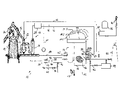
To this effect, a hot-blast stove has internal heat storage elements,
typically checker
bricks, and an associated burner for producing hot flue gas to heat the
checker
bricks. The burner may be internal or external. To permit hot gas to pass
during the
heating phases, the hot-blast stove has a heating gas inlet and a flue gas
outlet.
They permit heating gas to flow from the burner through the stove and its heat
storage elements (checker bricks) and, through the flue gas outlet, to a flue
gas stack
or chimney. With an internal burner, the heating gas is produced by combustion
inside the stove. For the heating of high-pressure blast air, a conventional
hot-blast
stove further has a cold blast inlet connected to a cold blast main and a hot
blast
outlet connected to a hot blast main of the blast furnace. During the blowing
phases,
air is blown from the cold blast inlet, through the regenerative heater where
it is
heated up by the heat storage elements and then fed to the blast furnace via
the hot
blast outlet. Regenerative heaters are used to heat the blast to a temperature
in the
range of 1100 C to about 1250 C.
[0003] In recent years, the re-use of top gas in the blast received increasing
attention, since it enables notable reductions of CO2 emissions. Corresponding
installations recover blast furnace top gas and subject it, usually after
conventional
top gas cleaning, to a recycling process before injecting it back into the
blast furnace.
The recycling process includes CO2 separation for withdrawing CO2 from the
process. To this effect, a gas separation unit separates top gas into tail gas
that is
rich in CO2 (carbon dioxide) and into high calorific value process gas, rich
in CO
2
H8322879CA
(carbon monoxide). As suitable gas separation unit it has been suggested to
use a
pressure swing adsorption (PSA) or a vacuum pressure swing adsorption (VPSA)
unit or, alternatively, a CO2 scrubber unit. The tail gas may be fed through a
cryogenic unit to separate out pure CO2 or subjected to any other further
processing,
ideally resulting in CO2 capture and storage. The other gas stream, however,
i.e. CO-
enriched process gas, is fed back into the blast furnace as reducing gas,
whereby
altogether lower CO2 production is achieved.
[0004] The required heating of CO rich process gas may be carried out in
regenerative heaters. However, the replacement of an ambient air as cold blast
with
113 CO rich
process gas, i.e. a reducing gas, has considerable implications. In
particular,
special measures and precautions are necessary concerning the changeover
sequences between the heating and blowing cycles and vice-versa.
[0005] Among others, gas fed to the regenerative heater during the heating
phase
is generally oxidizing and therefore liable to react explosively with high
calorific
process gas supplied during the blowing cycle. In order to avoid that any
dangerous
quantity of oxidizing gas is present in the regenerative heater during the
changeover
to the blowing phase, PAUL WURTH proposed, in PCT application W02010/133476,
a method of operating the burners in a manner that ensures that any oxygen is
consumed in the regenerative heater. For the transition from the blowing phase
to the
heating phase, W02010/133476 proposes to push out the residual CO containing
process gas out of the regenerative heater with the flue gas of the burner.
[0006] However, W02010/133476 is silent about specific measures related to the
changeover from the blowing phase to the heating phase. In view of the fact
that
pressure in the regenerative heater during the blowing phase (on-blast
pressure) is
typically higher than pressure during the heating phase (on-gas pressure), it
may be
necessary to take specific measures before the burner(s) can be ignited.
Technical problem
[0007] In view of the foregoing, it is an object of the present invention to
provide an
improved method for operating regenerative heaters, in particular as regards
the
changeover from the blowing phase to the heating phase. This object is
achieved by
the method described below.
CA 2851749 2018-12-07
CA 02851749 2014-04-10
WO 2013/056870 PCT/EP2012/065830
3
General Description of the Invention
[0008] The method of operating regenerative heaters according to the invention
may be used in a blast furnace plant that comprises a blast furnace, a gas
separation
unit, e.g. a pressure swing adsorption (PSA) device and/or a vacuum pressure
swing
adsorption device (VPSA), configured for separating top gas from the blast
furnace
into a CO-enriched stream of so-called process gas (hereinafter also referred
to as
CO-enriched process gas) and a CO-depleted stream of so-called tail gas
(hereinafter also referred to as CO-depleted tail gas), and at least three
regenerative
heaters, each having internal heat storage elements, a cold blast inlet for
receiving
process gas from the gas separation unit and a hot blast outlet for feeding
process
gas to the blast furnace. The regenerative heaters are cyclically operated on
blast
and on gas:
o while a regenerative heater is operated on gas, hot flue gas is produced
with a
burner and the hot flue gas is caused to flow through the regenerative heater
so
as to heat the heat storage elements; and
o while a regenerative heater is operated on blast, process gas is blown
through
the regenerative heater so that the process gas takes up heat from the heat
storage elements.
[0009] During a changeover of a regenerative heater from on-blast to on-gas
operation, the regenerative heater is purged from process gas using flue gas
collected after having flown through at least one of the regenerative heaters.
[0010] Preferably, the cyclic operations of the regenerative heaters are
dephased
amongst each other such that, at any one time, at least one of the
regenerative
heaters is operated on blast while at least one of the other regenerative
heaters is
operated on gas. The purging of the regenerative heater undergoing the
changeover
is then preferably effected with flue gas from the at least one other
regenerative
heater that is operated on gas at the time of the changeover. The flue gas
used to
purge may be directly fed from the at least one other regenerative heater that
is
operated on gas to the regenerative heater undergoing the changeover.
[0011] Alternatively or additionally, the purging of the regenerative heater
undergoing the changeover is effected with flue gas previously stored in a gas
storage, e.g. in a CCS (CO2 capture and storage) unit.
CA 02851749 2014-04-10
WO 2013/056870 PCT/EP2012/065830
4
[0012] Typically, a regenerative heater operated on blast is at an on-blast
pressure
(typically in the range of 5 to 7 bar (absolute)), whereas a regenerative
heater
operated on gas is at an on-gas pressure (typically in the range of 0.9 to 1.3
bar
(absolute)) lower than the on-blast pressure. Therefore, preferably, during a
changeover of a regenerative heater from on-blast to on-gas operation,
residual
process gas is released from the regenerative heater undergoing the changeover
so
as to depressurize it prior to purging with flue gas.
[0013] According to a preferred embodiment of the invention, such release of
process gas is at least partly effected into a top gas recovery installation
provided for
leading top gas from the blast furnace to the gas separation unit. The top gas
recovery installation may comprise a top gas conduit (e.g. a top gas
downcomer), a
gas cleaning installation (e.g. with a dry dust-catcher followed by a wet dust-
scrubber), arranged downstream of the blast furnace and upstream of the gas
separation unit. As top gas pressure upstream the gas separation unit is
typically
comprised in the range of 3 to 5 bar (absolute), after depressurization into
the top gas
recovery installation, it may be necessary to further depressurize the
regenerative
heater. That further depressurization may be effected by releasing process gas
into a
gas holder provided for storing tail gas. The gas holder is preferably held at
a
pressure slightly higher than atmospheric pressure (e.g. in the range of 1 to
1.5 bar
(absolute), preferably at 1.1 bar).
[0014] Instead of depressurizing first into the top gas recovery installation
and then
into the tail gas holder, the depressurization may, alternatively, be carried
out entirely
into the tail gas holder. In case of a 4-stoves plant, depressurization may
also be
effected by relieving the residual process gas into the 4th stove.
[0015] Preferably, process gas left over in the regenerative heater undergoing
the
changeover after the depressurization is (forcibly) expelled by the flue gas
and burnt
off or, (forcibly) expelled by the flue gas into the tail gas holder.
Advantageously, in
order to avoid that the CO concentration of the gas stored in the tail gas
holder drops
below a certain level, process gas is conveyed into the gas holder at most as
long as
CO concentration in the expelled process gas (which is increasingly
contaminated
with the flue gas) amounts to a predetermined percentage (which has to be
determined based upon the relevant plant parameter) of CO concentration in the
tail
gas. Preferably, any expelled process gas not conveyed to the gas holder is
burnt off.
CA 02851749 2014-04-10
WO 2013/056870 PCT/EP2012/065830
[0016] An aspect of the present invention concerns a blast furnace plant that
is
configured and arranged for carrying out the method.
Brief Description of the Drawings
[0017] Further details and advantages of the present invention will be
apparent
5 from the following detailed description a limiting embodiment with
reference to the
attached drawing, wherein:
FIG.1 is a block schematic diagram of a blast furnace plant configured for
carrying
out the method according to a preferred embodiment of the invention.
Description of Preferred Embodiments
[0018] Fig. 1 shows block schematic diagram of a blast furnace plant 10
configured
for carrying out the method according to a preferred embodiment of the
invention.
[0019] The blast furnace plant 10 comprises a blast furnace 12 and a plurality
of at
least three regenerative heaters 14.1, 14.2 and 14.3. The blast furnace plant
is
furthermore equipped with a top gas recirculation installation that recovers
top gas 16
from the top of the blast furnace 12 and feeds part of the recovered top gas
through a
recycling process before injecting it back into the blast furnace. The top gas
recirculation installation includes a top gas recovery installation 18, which
collects the
top gas 16 at the top of the blast furnace 12 and subjects the top gas to an
initial
cleaning to remove e.g. dust particles. In the example illustrated in Fig. 1,
the top gas
recovery installation 18 is comprised of uptakes 20, downcomer 22, a dry dust-
catcher 24 and a gas washer 26 (including e.g. a spray washer and an
electrical
precipitator). Downstream of the gas washer, the cleaned top gas is subjected
to CO2
removal in a gas separation unit 28 (e.g. a PSA device). The CO2 removal unit
produces two streams of gas: a CO2 rich tail gas 30 (which still contains
about 10 to
15% CO by volume) and a CO rich process gas 32. The CO2 rich tail gas 30 may
additionally be fed through a cryogenic unit (not shown) to separate pure CO2
out of
the CO2 rich tail gas. The pure CO2 may subsequently be pumped into the ground
for
storage. The CO rich process gas 32 is heated up and fed back into the blast
furnace
12 as reducing gas.
[0020] The heating of the CO rich process gas is carried out in the
regenerative
heaters 14.1, 14.2 and 14.3. Each of the regenerative heaters 14.1, 14.2, 14.3
CA 02851749 2014-04-10
WO 2013/056870 PCT/EP2012/065830
6
comprises a first chamber 34 ("combustion chamber") and a second chamber 36
("checker chamber"). The regenerative heaters 14.1, 14.2, 14.3 are cyclically
operated on blast (blowing phase) and on gas (heating phase).
[0021] During the heating phase, fuel gas and oxidizing gas are fed to the
burner
38 via gas inlets 40 and 42, respectively. The fuel and oxidizing gas are
ignited and
their combustion creates hot flue gasses, which ascend through the first
chamber 34
into a dome 44. The dome 44 deviates the hot flue gasses and feeds them into
the
second chamber 36 comprising heat storage elements, generally in the form of
checker bricks 46. The heat storage elements define a multiplicity of small
passageways through which the hot flue gasses pass downwardly to exit the
regenerative heater 14.1, 14.2 or 14.3 through a flue gas outlet 48 in the
lower
portion of the second chamber 36. Flue gas may finally be disposed of via a
chimney
82. More preferably, however, flue gas is dried and stored in an underground
CO2
storage 84.
[0022] During the subsequent blowing phase, process gas 32 is blown into the
second chamber 36 through the cold blast inlet 50 in the lower portion of the
second
chamber 36. As the process gas passes through the passageways between the heat
storage elements, heat is transferred from the checker bricks 46 to the
process gas.
At the top of the second chamber 36, the hot process gas is fed, via the dome
44,
into the first chamber 34. The hot process gas flows downwardly through the
first
chamber and then exits the regenerative heater 14.1, 14.2 or 14.3 through the
hot
blast outlet 52, which is connected to the hot blast line 54. The hot blast
line 54 feeds
the hot process gas into the blast furnace 12.
[0023] The gas separation unit 28 is connected to a tail gas network that
comprises, in particular a tail gas holder 56. A part of the tail gas 30 is
used to fuel
the burners 38 of the regenerative heaters 14.1, 14.2 and 14.3. To this end,
the (low-
calorific) tail gas is led via the conduit 31 and mixed with high-calorific
gas 58 (e.g.
coke oven gas). The mixture is then fed to the burner 38, where it serves as
the
combustible. The burner 38 could be fed with air to burn the mixture of tail
gas and
high-calorific gas. Fig. 1 shows a more preferred solution, according to which
flue gas
from the regenerative heaters 14.1, 14.2, 14.3 is mixed with pure oxygen 60 to
form
an oxidizing gas. The oxidizing gas preferably has a composition of about 80 %
of
CO2 (and residual nitrogen) by volume and about 20 `)/0 of 02 by volume. The
CA 02851749 2014-04-10
WO 2013/056870 PCT/EP2012/065830
7
advantage of such oxidizing gas mixture is that one can use a burner that
works also
with air. It should be noted that the mixture of combustible gas could also be
burnt in
pure oxygen, provided that appropriate burners are used.
[0024] The cyclic operations of the regenerative heaters 14.1, 14.2, 14.3 are
dephased amongst each other such that, at any time during the normal operation
of
the blast furnace plant 10, one of the regenerative heaters 14.1, 14.2, 14.3
is
operated on blast while the two others are operated on gas. The transitions
between
heating and blowing and vice-versa are synchronized, in such a way that when
the
regenerative heater on blast changes over to on-gas operation, one of the
regenerative heaters on gas takes over the blowing.
[0025] In the changeover of a regenerative heater (in the following
explanation it
will be assumed that this is regenerative heater 14.1) from blowing to heating
operation, first, the hot blast valve 62 and the cold blast valve 64 are
closed. At that
time, the residual process gas inside the regenerative heater 14.1 is still at
the on-
blast pressure of about 6 bar (absolute). Depressurization of the regenerative
heater
undergoing the changeover may be then carried out in one or in two steps. In
case of
a one-step depressurization, process gas is released gas from the regenerative
heater 14.1 into the tail gas network, in particular into the tail gas holder
56, via
conduit 68, or, in case of a 4-stove plant, into the fourth hot blast stove
(not shown).
.. In case of a two-step depressurization, a first depressurization is
achieved by
releasing process gas from the regenerative heater 14.1 into the top gas
recovery
installation 18, via the depressurization conduit 66. Gas pressure in the top
gas
recovery installation 18 is typically comprised in the range from 3 to 5 bar
(absolute),
e.g. 4.5 bar (absolute). After equalization of pressures, the depressurization
conduit
66 is closed. A second depressurization is then achieved into the tail gas
network, in
particular into the tail gas holder 56, via conduit 68. Gas pressure in the
tail gas
network is typically about 1.1 bar (absolute), so that the regenerative heater
may be
depressurized to that pressure during the second depressurization step. After
equalization of pressures, the regenerative heater is still full of process
gas.
[0026] The regenerative heater 14.1 undergoing the changeover is then purged
using flue gas from the regenerative heater that is operated on gas at the
time of the
changeover (it will be assumed, for sake of the explanation that this is
regenerative
heater 14.3). The flue gas is fed from the flue gas outlet of the regenerative
heater
8
H8322879CA
14.3 to the flue gas recirculation conduit 70 of the regenerative heater 14.1.
At that
time, the oxygen supply valve 72, the high-calorific gas supply valve 74 and
the tail
gas supply valve 76 are closed, and the burner 38 is off. A pump or a
compressor 78
creates the necessary pressure difference to introduce the flue gas into the
regenerative heater 14.1. As flue gas is led into the regenerative heater
14.1, residual
process gas is expelled into the tail gas network, via the conduit 68. The
more
process gas is expelled, the more it will be contaminated with injected flue
gas. At
some point, it will no longer be possible to lead the expelled process gas
(which is in
fact a mixture of process gas and flue gas) into the tail gas network because
the
quality of the tail gas would be too much deteriorated. Preferably, the
conduit 68 is
closed when the CO concentration in the expelled process gas has diminished to
a
certain percentage by volume of the nominal CO concentration in the tail gas
network. If the purging still has to be continued, the mixture of process gas
and flue
gas may be fed to a flare 80 or into a gas separation unit (not shown) that
removes
any residual amount of CO. Purging is stopped when the concentration of CO in
the
regenerative heater 14.1 has come down to a value that is safe for starting
the burner
38.
[0027] If it should not be possible, due to exceptional circumstances, to
collect
(enough) flue gas for purging a regenerative heater at the flue gas outlet of
one of the
other regenerative heaters, flue gas previously stored in the CO2 storage 84
may be
used. To this end, conduit 86 is opened.
[0028] As concerns the changeover from the heating to the blowing phase, care
has to be taken that there is no or only an uncritical amount of oxidizing gas
in the
regenerative heater when the cold blast valve 64 is opened and CO rich process
gas
enters the second chamber. The CO rich process gas and the oxidizing gas could
otherwise form a dangerous mixture that could ignite and damage the
regenerative
heater. In order to ensure that no oxidizing gas is present at the beginning
of the
blowing phase, at the end of the heating phase, different measures can be
taken.
According to a first option, first oxygen supply is stopped by closing the
oxygen
supply valve 72. Consequently, no more oxygen is fed into the system. In order
to
consume any residual oxygen, fuel gas mixture continues to be fed to the
burner 38.
When all the oxidizing gas is gone, the combustion stops by itself. The
supplies of the
fuel gas mixture and flue gas are now interrupted. The blowing phase can begin
CA 2851749 2018-12-07
CA 02851749 2014-04-10
WO 2013/056870 PCT/EP2012/065830
9
safely by opening the cold blast valve 64, whereby the regenerative heater is
brought
to the on-blast pressure, and then the hot blast valve 62. During a short time
at the
beginning of each blowing phase, flue gas will be fed to the blast furnace 12.
Nevertheless, the amount of flue gas is not sufficient to disturb the
operation of the
blast furnace. According to a second option for avoiding that oxidizing gas is
present
in the regenerative heater at the beginning of the blowing phase, the
combustion is
stopped in the conventional way (i.e. by stopping arrival of the fuel gas
mixture first),
which leads to residual oxygen in the regenerative heater. This oxygen is then
removed from the regenerative heater by an additional purging phase with waste
gas
.. from another regenerative heater.
[0029] While a specific embodiment has been described in detail, those skilled
in
the art will appreciate that various modifications and alternatives to those
details
could be developed in light of the overall teachings of the disclosure.
Accordingly, the
particular arrangements disclosed are meant to be illustrative only and not
limiting as
to the scope of the invention, which is to be given the full breadth of the
appended
claims and any and all equivalents thereof.
It is worthwhile noting, in particular, that the burners of the regenerative
heaters could
be fed with a different fuel gas or a different mixture of fuel gas. A mixture
of tail gas
and coke oven gas, as discussed in the example, is, however, a preferred
option,
since both types of gas are typically available in a blast furnace plant
operating with
top gas recycling. As concerns the oxidizing gas, which in the example is a
mixture of
oxygen and recirculated flue gas, an alternative solution would be to burn
part of the
tail gas with an excess of oxygen in a pre-combustion chamber, so as to
achieve the
desired mixture of inert gas (burnt tail gas, essentially CO2) and oxygen.
CA 02851749 2014-04-10
WO 2013/056870
PCT/EP2012/065830
Legend:
10 Blast furnace plant 70 Flue gas recirculation conduit
12 Blast furnace 72 Oxygen supply valve
14.1, Regenerative heaters 74 High-calorific gas supply
14.2, valve
14.3 76 Tail gas supply valve
16 Top gas 78 compressor
18 Top gas recovery installation 80 Flare
Uptake 82 Chimney
22 Downcomer 84 CO2 storage
24 Dry dust-catcher 86 Conduit
26 Gas washer
28 Gas separation unit
(CO-depleted) Tail gas
31 Conduit
32 (CO-enriched) Process gas
34 First chamber
36 Second chamber
38 External or internal type
burner
Gas inlet for oxidizing gas
42 Gas inlet for fuel gas
44 Dome
46 Checker bricks
48 Flue gas outlet
Cold blast inlet
52 Hot blast outlet
54 Hot blast line
56 Tail gas holder
58 High-calorific gas
Oxygen
62 Hot blast valve
64 Cold blast valve
66 Depressurization conduit
68 Conduit