Note: Descriptions are shown in the official language in which they were submitted.
Mk 02852191 2014-08-01
ROBOT-DEPLOYED ASSEMBLY TOOL AND METHOD FOR INSTALLING FASTENERS IN
AIRCRAFT STRUCTURES
BACKGROUND
The disclosure relates generally to an assembly tool and
method and, more particularly, to a robot-deployed assembly tool
and method for installing fasteners in an interior area of an
aircraft wing box or other structure.
When attaching wing skins to the spar caps and bulkheads using
various fasteners during wing box assembly, for example, operator
mechanics may be required to enter into the wing box and work with
various hand tools in order to complete the assembly process.
Typically, the operator locates an intended drilling location,
manually drills a stack-up of spar cap and wing skin or bulkhead
flange and wing skin, removes the detail parts and then performs
de-burring and cleanup. The operator may then reposition the parts
and align the drilled holes prior to fastener installation.
Carrying many often heavy tools and performing the highly
repetitive assembly actions in an interior area of a wing box or
similar structure can cause fatigue, discomfort and possible injury
to the operator. Adequate lighting and ventilation must also be
maintained to ensure satisfactory working conditions.
There is, accordingly, a need for a mechanism for assisting an
operator in performing fastener installation or other repetitive
assembly tasks without the necessity of having the operator enter
into an interior area of an aircraft wing box or other structure.
SUMMARY
An embodiment of the disclosure provides an assembly system for
assembling a wing box of an aircraft, the wing box defining an
enclosed area accessible through at least one access opening, the
assembly system providing a robot located outside the wing box that
1
ak 02852191 2014-08-01
extends and guides a robot arm into the enclosed area of the wing
box through the at least one access opening and an assembly tool
mounted to the robot arm. The assembly tool provides a positioning
mechanism for positioning the assembly tool in the enclosed area, a
clamp for clamping the assembly tool to an interior surface of the
enclosed area of the wing box, and an electromagnet located outside
the wing box positioned to activate the clamp to clamp the assembly
tool to the interior surface.
A further embodiment provides a robot arm link operably coupled to
the robot arm and a connector link operably coupled to the robot
arm link.
Another embodiment provides a vision module in the positioning
mechanism for guiding the assembly tool to a fastener location in
the enclosed area.
An embodiment provides a camera in the vision module that guides
the assembly tool to a fastener location in the enclosed area by a
laser beam passing through a notch in the clamp.
In another embodiment at least one of a light source and a laser
sensor in the vision module is provided.
Another embodiment provides a fastener installing mechanism for
installing a fastener in the hole and a securing utility tool in
the fastener installing mechanism for securing a fastener securing
element to the fastener.
2
ak 02852191 2014-08-01
A further embodiment provides a dispensing utility tool in the
fastener securing mechanism for dispensing the fastener securing
element to the fastener.
Another embodiment provides actuators in the assembly tool for
moving the dispensing utility tool and the securing utility tool
into dispensing and securing positions, respectively.
A further embodiment a clamping foot operably coupled to the clamp
for being magnetically clamped to an interior surface of the
enclosed area.
Another embodiment provides a gap between a wing spar cap and a
skin panel or between a wing bulkhead flange and a skin panel that
is eliminated by clamping the clamping foot to the interior surface
of the enclosed area when the electromagnet located outside of the
wing box activates the clamp thereby enabling substantially burr-
less drilling of the hole through the wing spar cap and the skin
panel or the wing bulkhead flange and the skin panel from outside
of the wing box.
Another embodiment provides a taper of the clamping foot for
clamping the assembly tool to the interior surface of the enclosed
area at corner fastener locations.
The features, functions, and advantages can be achieved
independently in various embodiments or may be combined in yet
other embodiments.
3
ak 02852191 2014-08-01
BRIEF DESCRIPTION OF THE DRAWINGS
The novel features believed characteristic of the embodiments
are set forth in the appended claims. The embodiments themselves,
however, as well as a preferred mode of use, further objectives and
advantages thereof, will best be understood by reference to the
following detailed description of advantageous embodiments when
read in conjunction with the accompanying drawings.
Figure 1 is an illustration of an aircraft in which
advantageous embodiments of the disclosure may be implemented;
Figure 2 is an illustration of a section of a wing box for an
aircraft and a robot-deployed assembly tool for assembling the wing
box in accordance with an advantageous embodiment of the
disclosure;
Figure 3 is an illustration of the robot arm of the robot-
deployed assembly tool of Figure 2 in accordance with an
advantageous embodiment of the disclosure;
Figures 4A and 4B are illustrations of an assembly tool module
of the robot-deployed assembly tool of Figure 2 in nested and
deployed positions, respectively, in accordance with an
advantageous embodiment of the disclosure;
Figures 5, 6 and 7 are illustrations showing different views
of the deployed assembly tool module of Figure 4B;
Figure 8 is an illustration of an assembly tool module in
accordance with a further advantageous embodiment of the
disclosure;
Figure 9 is an illustration of a top view of the assembly tool
module of Figure 8;
Figure 10 is an illustration of an assembly tool module in
accordance with yet a further advantageous embodiment of the
disclosure; and
4
ak 02852191 2014-08-01
Figure 11 is a flowchart that illustrates a method for
installing fasteners in a wing box of an aircraft in accordance
with an advantageous embodiment of the disclosure.
DETAILED DESCRIPTION OF PREFERRED EMBODIMENTS
With reference now to the figures, and, in particular, with
reference to Figure 1, an illustration of an aircraft is depicted
in which advantageous embodiments of the disclosure may be
implemented. More particularly, aircraft 100 is an example of a
structure in which a robot-deployed assembly tool and an assembly
method in accordance with advantageous embodiments of the
disclosure may be implemented.
In this illustrative example, aircraft 100 has wings 102 and
104 attached to body 106. Aircraft 100 includes wing mounted
engines 108, 110, 112 and 114. Further, aircraft 100 also includes
body mounted engine 116, body mounted engine 118 and horizontal and
vertical stabilizers 120 and 122, respectively.
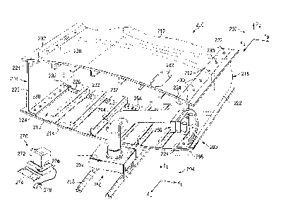
Figure 2 is an illustration of a section of a wing box for an
aircraft and a robot-deployed assembly tool for assembling the wing
box in accordance with an advantageous embodiment of the
disclosure. Specifically, Figure 2 illustrates a portion of wing
box 200, for example, although not limited to wings only, such as
one of wings 102 and 104, and robot-deployed assembly tool 250 for
assembling components of wing box 200. The interior area of wing
box 200, generally designated by reference number 210, is an
example of a confined or bounded area within which robot-deployed
assembly tool 250 may be advantageously employed, although it
should be understood that advantageous embodiments are not limited
to employing robot-deployed assembly tool 250 in any particular
area.
5
ak 02852191 2014-08-01
=
Wing box 200 is comprised of a plurality of components
including top skin panel 212, bottom skin panel 214, wing spars 216
and 218, and wing box bulkhead 220. Wing spars 216 and 218 each
include wing spar web portion 222 and wing spar cap portions 224,
and wing box bulkhead 220 includes bulkhead flanges including
bulkhead flange 226. As shown in Figure 2, assembly of wing box
200 requires that cap portions 224 of wing spars 216 and 218 and
bulkhead flanges 226 of wing box bulkhead 220 be fastened to top
and bottom skin panels 212 and 214 and to each other at numerous
fastener locations, including centrally located straight fastener
locations such as locations 230, and corner fastener locations such
as locations 232, using appropriate fasteners (not illustrated in
Figure 2). Yet other fastening operations may also be performed if
needed. The fasteners may include, but are not limited to, bolts
or screws that may extend through aligned openings in the
components to be assembled and may be secured by nuts, collars or
other suitable securing elements.
The fastening operation may require access to interior area
210 of wing box 200 and this is typically achieved, in the case of
large wing boxes, by an operator entering into interior area 210
and using appropriate hand tools needed to complete the assembly
process. As indicated previously, performing the highly repetitive
assembly actions in the interior area of a wing box can cause
fatigue, discomfort and possible injury to the operator.
Advantageous embodiments of the disclosure provide a robot-
deployed assembly tool, such as robot-deployed assembly tool 250 in
Figure 2 to facilitate assembly of the components of wing box 200
by making it unnecessary for an operator to enter into interior
area 210 of wing box 200.
More particularly, robot-deployed assembly tool 250 generally
comprises robot body 252, robot arm 254 and assembly tool module
6
ak 02852191 2014-08-01
256. Robot body 252 may be mounted on track 258 for movement to
desired assembly positions, although it should be understood that
other mechanisms may be used to provide mobility to robot-deployed
assembly tool 250, and it is not intended to limit advantageous
embodiments to any particular mechanism for moving robot-deployed
assembly tool 250. Robot arm 254 may extend from robot body 252
and carry assembly tool module 256 at the outer end thereof.
As shown in Figure 2, one or more access openings that are
typically provided in wing box 200 for maintenance purposes and the
like, may provide robot arm 254 and assembly tool module 256
attached thereto with access to interior area 210 of wing box 200.
In the advantageous embodiment illustrated in Figure 2, one access
opening 242 is provided in top skin panel 212 and one access
opening 244 is provided in bottom skin panel 214. It should be
understood, however, that the number of access openings and their
positioning is intended to be exemplary only, as one or more access
openings can be provided at any desired location or locations of
wing box 200.
Figure 2 illustrates robot arm 254 of robot-deployed assembly
tool 250 inserted into interior area 210 of wing box 200 through
access opening 244 in bottom skin panel 214. Robot arm 254 may be
extended to position assembly tool module 256 to perform fastening
operations, in this example, to fasten wing spar cap 224 to bottom
skin panel 214 at fastener location 280.
After fastening operations are completed at fastener location
280, robot arm 254 may be operated to move assembly tool module 256
to a second fastener location to perform fastening operations at
the second fastener location. The process may be repeated until
fastening operations have been performed at all fastening locations
accessible through access opening 244. Robot-deployed assembly
tool 250 may then be moved to another access opening, for example,
7
ak 02852191 2014-08-01
access opening 242, and fastening operations may then be performed
at fastener locations accessible through access opening 242. The
process may be repeated until all fastening operations have been
completed.
Robot-deployed assembly tool 250 may be operated by a user
from a remotely-located control console shown at 270. Control
console 270 may, for example, be a computer having video display
terminal 272, keyboard 274, storage devices 276 which may include
permanent and removable storage media, and mouse 278. Additional
input devices may also be included within computer 270 such as, for
example, a joystick, trackball, touchpad and the like.
Figure 3 is an illustration of robot arm 254 of robot-deployed
assembly tool 250 of Figure 2 in accordance with an advantageous
embodiment of the disclosure. Robot arm 254 may include a
plurality of links including first link 302 connected to robot base
252 in Figure 2, last link 304 having assembly tool module 256 in
Figure 2 attached thereto, as will be described hereinafter, and a
plurality of intermediate links including links 306 and 308. The
links of robot arm 254 may be positioned relative to each other and
to interior area 210 by hydraulically, electrical or pneumatically
actuated control mechanisms, not shown, known to a person with
ordinary skill in the art. The control mechanisms may move robot
arm 254 between a nested position (not shown in Figure 3) in which
robot arm 254 is fully retracted and an extended position in which
the arm is fully extended (also not shown). In the advantageous
embodiment illustrated in Figure 3, the links are configured as C-
channel-shaped links and may be retracted or extended by rotating
one link with respect to another. It should be understood,
however, that robot arm 254 can be formed of links of other
suitable configurations, for example, links in the form of blocks
of rectangular cross-section, and the links may be extended and
8
ak 02852191 2014-08-01
retracted by other mechanisms without departing from advantageous
embodiments.
Figures 4A and 4B are illustrations of assembly tool module
256 shown in Figure 2 in nested 401 and deployed 403 positions,
respectively. Figures 5, 6 and 7 are illustrations of different
views of the deployed assembly tool module 256 of Figure 4B. The
directions of the different views are indicated by arrows in Figure
4B referring to each of Figures 5-7. Figure 7 illustrates assembly
tool module 256 with various portions, including utility tools 450
and 452, removed for clarity. Assembly tool module 256 may include
several components which are described in detail below with
reference to Figures 4A, 4B and 5-7.
Connector link 402 is attached to last link 304 of robot arm
254, and may function as an interface between the robot arm and an
assembly tool generally designated by reference number 406.
As best shown in Figure 4B, connector link 402 may be mounted
to robot arm link 304 via a deploying mechanism, generally
designated by reference number 410, that may include, but is not
limited to, a motor and an appropriate set of gears to rotate the
connector link and the assembly tool mounted thereto relative to
robot arm link 304 between nested position 401 shown in Figure 4A
and deployed position 403 shown in Figure 4B.
In the advantageous embodiment illustrated in Figures 4A-7,
robot arm links are configured as C-channel-shaped links as
illustrated in Figure 3, and connector link 402 is also configured
as a C-channel-shaped link and is sized to be received within robot
arm link 304 when in nested position 401 shown in Figure 4A. It
should be understood, however, that connector link 402 may be of
other appropriate configurations, and it is not intended to limit
advantageous embodiments to any particular configuration.
9
ak 02852191 2014-08-01
Connector link 402 may support vision module 412 and actuator
mechanism 414 that provides for rotation of assembly tool 406 as
will be described hereinafter. Connector link 402 may be connected
to assembly tool 406 via a plurality of hinges 416 connected to
back plate 422 as will also be described more fully hereinafter.
Vision module 412 may include camera 472, light source 474 and
laser sensor 476. As best shown in Figure 4B, vision module 412
may be movable up and down along rails 427 between a stowed
position (not shown) within connector link 402 for protection
before deployment of assembly tool module 256 from robot arm link
304, and a deployed position shown in Figure 4B. An operator may
use camera 472 and light source 474 of vision module 412 to guide
movement of robot arm 254 within interior area 210 of wing box 200.
Laser sensor 476 may serve as a position check for an intended
drilling location. Vision module 412 may also be used to check for
drilling quality after a drilling operation has been performed, for
example, without limitation, to check the diameter and roundness of
a drilled hole, hole edge distance and its perpendicularity to the
drilled surface, and, in general, may be used to inspect the
overall fastening operation.
As best shown in Figure 5, assembly tool 406 may be connected
to connector link 402 by three plates, referred to herein as back
plate 422, middle plate 424 and front plate 426. As indicated
above, back plate 422 may be hinged to the top of connector link
402 by four hinges 416 to provide for outward rotation of assembly
tool 406 relative to connector link 402. Back plate 422 may
include two vertical rails 428 on the front surface thereof.
Middle plate 424 may include two vertical grooves 430 and
horizontal rail 432, and front plate 426 may include horizontal
groove 434 and round stud 436, shown in Figure 7. Vertical rails
428 of back plate 422 may be slidably received in vertical grooves
ak 02852191 2014-08-01
430 of middle plate 424 so that the middle plate can glide up and
down along the vertical rails. Horizontal rail 432 of middle plate
424 may be received in horizontal groove 434 of front plate 426, so
that the front plate may glide horizontally relative to the middle
plate. Round stud 436 may provide a mounting and rotation for
assembly tool housing 440 through rotation actuator 442 mounted at
the top corner of front plate 426.
Tool assembly housing 440 is a frame that may support various
utility tools carried by assembly tool 406 and may include a set of
mounting and sliding plates for the utility tools. Tool motion
actuator 446 may be attached to a side plate at the top of the
housing.
Utility tools of assembly tool 406 according to an
advantageous embodiment may include dispensing tool 450 for
dispensing a collar/nut/washer and securing tool 452 for securing a
collar/nut dispensed by dispensing tool 450. As will be described
hereinafter, both dispensing tool 450 and securing tool 452 may be
movable up and down by tool motion actuator 448 away from and
toward a drilled hole so as to be able to perform their functions.
Clamping foot 454 may be attached to the lower legs of housing
440 via four bolts 456. Clamping foot 454 may be formed of steel
or another suitable material and enables electromagnetic clamping
to be achieved in conjunction with operation of an external
portable electromagnet illustrated at 298 in Figure 2. Clamping
foot 454 functions to stabilize and clamp components being
drilled/assembled between clamping foot 254 and the portable
magnet, and may eliminate any gap between the components prior to
drilling. This clamping process may enable substantially burr-less
drilling of a hole through the components. Clamping foot 454 may
include fork-like cutouts 458 extending from either end to avoid
interference with fasteners when the foot is moved to and set at
11
ak 02852191 2014-08-01
new drilling locations. Hole 460 in clamping foot 454 may provide
drilling clearance. Channel notch 462 may be included in clamping
foot 454 to provide an open path for a laser beam from vision
module 412 to help locate a drilling position.
In general, clamping foot 454, housing 440 and utility tools
450 and 452 comprise a subassembly of assembly tool 406 that may be
moved to maintain tool perpendicularity to a drilled surface. The
subassembly enjoys the combinations of two rotations (rotation 405
shown in Figure 5 and rotation 407 shown in Figure 7) and two
translations (vertical 409 and horizontal 411 as shown in Figure 5)
for minor positioning adjustment. Figure 6 illustrates various
motions and actions generally available using assembly tool module
256, using a table and correspondingly numbered arrows. According
to advantageous embodiments, all motions and utility tool actions
may be either pneumatically, electrically or hydraulically powered
and remotely controlled by control console 270, via various
actuators, linkages, etc., from external of the interior area
within which the robot-deployed assembly tool is to operate. It
should be understood, however, that other forms of power and remote
control mechanisms may also be utilized and it is not intended to
limit exemplary embodiments of the disclosure to any specific
manner of control.
Assembly tool module 256 illustrated in Figures 4A-7 may be
particularly effective at fastener locations that are centrally
located within a wing box (referred to as straight fastener
locations 230 in Figure 2). Robot mobility of the assembly tool
module 256 illustrated in Figures 4A-7 may be limited in corner
fastener locations (referred to as corner fastener locations 232 in
Figure 2) by structural interference. Figure 8 is an illustration
of an assembly tool module 256 in accordance with a further
advantageous embodiment of the disclosure. Figure 9 is an
12
ak 02852191 2014-08-01
illustration of a partial top view of assembly tool module 256 of
Figure 8 looking in the direction of arrows
9 - 9 in Figure 8. The assembly tool module 256 shown in Figures 8
and 9 may be particularly suitable for performing fastening
operations at corner locations such as corner fastener locations
232 in Figure 2. Assembly tool module 256 in Figures 8 and 9 may
be advantageously attached to a second robot arm (not shown) that
will work side-by-side with assembly tool module 256 shown in
Figures 4A-7 that may carry utility tools for straight fastener
locations.
Assembly tool module 256 may include transition plate 802,
shown in Figures 8 and 9, which replaces housing 440 of assembly
tool 406 illustrated in Figures 4A-7. Transition plate 802 may be
connected to a group of motion control plates (back plate 822,
middle plate 824 and front plate 826) that may be similar to plates
422, 424 and 426 in assembly tool module 256 shown in Figures 4A-7.
Transition plate 802 maintains the rotational ability of assembly
tool 806 with respect to front motion control plate 826 and may
provide the building foundation for new tool components. To reach
corner fastener locations with agility, assembly tool module 256
shown in Figures 8 and 9 may possess four additional degrees of
freedom (one shaft rotation illustrated by arrow 803 and three tool
translations illustrated by arrows 805, 807, and 809 in Figure 8).
Utility bracket 810 may be attached to transition plate 802.
Utility bracket 810 provides tool shaft support, and may also house
front vision module 812, actuator 814 and a rack and glide track,
generally designated by reference number 816.
Front vision module 812 may be located at the upper left side
of utility bracket 810. Front vision module 812 may include camera
892, light source 894, and laser unit 896, and may be provided in
addition to a back vision module (not shown in Figures 8 and 9).
13
ak 02852191 2014-08-01
Front vision module 812 may further help an operator navigate the
robot deployed assembly tool within the interior area 210 of wing
box 200.
Rack and pinion drive 815 is a set of gears to provide rotary
tool shaft motion that switches and positions the utility tools for
a desired hole location. The rack may glide on a track attached to
utility bracket 810 while the pinion may be keyed to rotary tool
shaft 818.
Rotary tool shaft 818 enables the switching of utility tools
850 and 852 and clamping foot 860. Upper shaft lock 820 and a
lower pin (not shown) keep shaft 818 in place on utility bracket
810. The lower end of shaft 818 may be attached to tool deploy
platform 870.
Tool deploy platform 870 may be a T-shaped component at the
lower end of rotary shaft 818. It may hold utility tools 850 and
852, clamping foot 860, and their respective activation actuators.
The combinations of rotating tool shaft and actuator motions
facilitate the deployment of utility tools 850 and 852 and clamping
foot 860.
Tool motion guide set 872 is a linear motion guidance that may
consist of slider 874, guide housing 876 and tool holder 878 for
each tool. The linear motion may be initiated by actuator 880
using, for example, either a hydraulically, electrical or
pneumatically powered piston rod.
Tapered clamping foot 860 occupies a central position of tool
deploy platform 870. It may be attached to angle holder 882 for
easy reach and to avoid interference. Clamping may be activated
by, but is not limited to, an external electromagnet 298, shown in
Figure 2, through a stack of aluminum skin and spar cap or aluminum
skin and bulkhead flange of a typical wing box.
14
ak 02852191 2014-08-01
Figure 10 is an illustration of an assembly tool module 256 in
accordance with yet a further advantageous embodiment of the
disclosure. The assembly tool module 256 shown in Figure 10 may be
similar to assembly tool module 256 illustrated in Figures 8 and 9.
Assembly tool module 256 shown in Figure 10 differs from
assembly tool module 256 shown in Figures 8 and 9 in that
dispensing tool 1050 and securing tool 1052 may be deployed with
swing-arm features. Specifically, clamping foot 1060 maintains
clamping throughout an entire cycle for one fastener installation.
This may help ensure precise burr-less drilling and may reduce
cycle time by not having to release and retract the foot between
dispensing and securing operations as in assembly tool module 256
illustrated in Figures 8 and 9. Assembly tool module 256 shown in
Figure 10 provides many controllable motions. Figure 10 also
illustrates the various motions and actions that may be available
using assembly tool module 256 using a table and correspondingly
numbered arrows.
Components of assembly tool module 256 shown in Figure 10 may
include dispensing tool swing arm 1090 and securing tool swing arm
1092. Dispensing tool swing arm 1090 may be fitted to rotary tool
shaft 1018 and may be swung around shaft 1018 using actuator 1094
attached to tool deploy platform 1070. Dispensing tool 1050 may be
attached to arm 1090 and hence swings with the arm.
Securing tool swing arm 1092 may be similar to dispensing tool
swing arm 1090 and controls the position of securing tool 1052. It
may be attached to the opposite side of tool deploy platform 1070
and may be caused to swing by actuator 1096.
In operation, a robot arm, not shown in Figure 10, may
position assembly tool module 256 at a desired drilling location
within a wing box, also not shown in Figure 10. Clamping of the
assembly tool module 256 to an internal surface of the wing box may
ak 02852191 2014-08-01
be activated by an external electromagnet and maintained during
drilling and fastener placement operations. With the foot clamping
still in place, actuator 1094 on tool deploy platform 1070 may
swing dispensing tool 1050 and position it over the tail portion of
a fastener in coordination with tool translation actuator 1098.
The dispensing tool 1050 may then retract to a default position
after dispensing a collar/nut. With the foot clamping still
activated, securing tool 1052 may be swung by actuator 1096 to
position securing tool 1052 over the dispensed collar/nut, again in
coordination with its tool translation actuator 1098, to secure the
collar/nut to the fastener.
Securing tool 1052 may then be retracted to a default position
(not shown), the clamping may be deactivated and the robot arm may
retract assembly tool module 1000 and move it to a next fastener
location.
To use the robot-deployed assembly tool 250 in accordance with
advantageous embodiments of the disclosure, fixed global coordinate
information, illustrated at 292 in Figure 2, may be stored in
control console 270 to control general robot movements. In
addition, fine positioning adjustments (illustrated by local
coordinates 292 in Figure 2) may be performed by the assembly tool
module using control console 270.
Figure 11 is a flowchart that illustrates a method for
installing fasteners in a wing box of an aircraft, such as wing box
200 of aircraft 100 in accordance with an advantageous embodiment
of the disclosure. The method is generally designated by reference
number 1100 and may begin by moving a robot-deployed assembly tool
250 along tracks 258 to the vicinity of an access opening 244 in a
wing box 200 to be assembled (Step 1102). Nested links, e.g.,
links 302-308, of a robot arm 254 of the robot-deployed assembly
tool 250 carrying an assembly tool module 256 may then be inserted
16
ak 02852191 2014-08-01
through the access opening 244 and into an interior area 210 of the
wing box 200 (Step 1104).
A connector link 402 of the assembly tool module 256 may then
be deployed from the last link 304 of the robot arm 254 to ready a
vision module 412 on the connector link 402 for deployment (Step
1106). The deployed vision module 412 may then be used to guide
robot movement, and the links 302-308 of the robot arm 254 may be
deployed successively, for example, by rotating one nested link
with respect to another, to guide the assembly tool module 256 to a
desired fastener location in the interior area 210 of the wing box
200 (Step 1108). An assembly tool 406 of the assembly tool module
256 may then be precisely positioned through local adjustment (Step
1110). A camera 472 and laser sensor 476 in the vision module 412
may be used to assist a user at control console 270 in performing
this fine adjustment, for example, by moving a cursor on video
display terminal 272 using mouse 278.
A determination may be made as to whether the assembly tool
406 is correctly positioned (Step 1112). If the assembly tool 406
is not correctly positioned (No output of Step 1112), the method
may return to step 1110 for further local adjustment of the
assembly tool 406 by the user. If the assembly tool 406 is
correctly positioned (Yes output of Step 1112), electro-magnetic
clamping of the assembly tool to an interior surface of the wing
box 200 may be externally activated by the user using an external
electromagnet 298 (Step 1114).
Drilling of a hole through wing box components to be
assembled, e.g., wing spar cap 224 and bottom skin panel 214, may
then be performed from externally of the wing box 200 (Step 1116).
Such drilling operation may include hole preparation such as
countersinking, for example. Because of the clamping operation,
any gap between the two components being drilled is substantially
17
ak 02852191 2014-08-01
=
eliminated resulting in substantially burr-less drilling. The
camera 472 and laser sensor 476 may be used by the user at control
console 270 to check the drilled hole after the drilling operation
to determine whether the hole is of an acceptable quality, both
inside and outside the hole (Step 1118). If the hole is not of
acceptable quality (No output of Step 1118), the hole may be
corrected as needed, for example, by a further drilling operation
(Step 1120).
If the drilled hole is of acceptable quality (Yes output of
Step 1118), an operator may then insert a fastener such as a bolt
or screw into and through the drilled hole from the exterior of the
wing box 200 (Step 1122), and a dispensing utility tool, for
example, dispensing tool 450 of tool assembly 406 may be caused to
deliver a fastener securing element such as a collar or nut to the
inserted fastener (Step 1124). An embodiment may include various
size collars or nuts and the mechanism to install the various size
collars or nuts. The dispensing utility tool 450 may then be moved
away to make room for a subsequent utility tool to follow. A
securing utility tool, for example, secur,ing utility tool 452 of
tool assembly 406 may then be moved into position (Step 1126) and
caused to perform required operations to permanently attach the
fastener by use of the securing device acting on the fastener, such
as gripping, swaging and/or tail-pin breaking operations on the
fastener securing element (Step 1128), and the assembly tool 406
may then be moved so that the dispensing utility tool will be in
the default position for the next fastener installation operation
(Step 1130).
The clamping may then be deactivated (Step 1132), and a
determination may be made whether there are more fastener locations
accessible through the access opening 244 at which fasteners are to
be installed (Step 1134). If there are more fastener locations
18
ak 02852191 2014-08-01
(Yes output of Step 1134), the robot arm 254 may retract the tool
406 and guide the tool 406 to another fastener location (Step 1136)
and the method may return to Step 1110 for processing/installing a
fastener at the new location.
If there are no further fastener locations accessible through
the access opening 244 (No output of Step 1134), a determination
may be made as to whether there are any further access openings
through which the robot-deployed assembly tool 250 should be
inserted to install additional fasteners (Step 1138). If there are
further access openings, for example, access opening 242 (Yes
output of Step 1138), the robot-deployed assembly tool 250 may be
withdrawn and moved to the next access opening 242 (Step 1140) and
the method returns to Step 1104. If there are no more access
openings (No output of Step 1138), the robot-deployed assembly tool
250 may be moved along tracks 258 to a stand-by position (not
shown) for the next assembly operation (Step 1142), and the process
sequence ends. The stand-by position may be a storage location
remote from the wing box 200 at which the robot-deployed assembly
tool 250 is stored for later use.
The description of advantageous embodiments has been presented
for purposes of illustration and description, and is not intended
to be exhaustive or limited to the form disclosed. Many
modifications and variations will be apparent to those of ordinary
skill in the art. For example, although advantageous embodiments
are described in connection with assembling a wing box for an
aircraft, the embodiments may also be used to assemble other types
of structures such as structures associated with ships and other
vehicles and buildings. Also, the assembly tool according to
advantageous embodiments can include different or additional
utility tools to perform different or additional assembly
operations. For example, the assembly tool can also include a
19
ak 02852191 2014-08-01
drilling utility tool to drill holes from inside a structure being
assembled rather than causing the holes to be drilled from the
exterior of the structure. Further, different advantageous
embodiments may provide different advantages as compared to other
advantageous embodiments. The embodiment or embodiments selected
are chosen and described in order to best explain features and
practical applications, and to enable others of ordinary skill in
the art to understand various embodiments with various
modifications as are suited to particular uses that are
contemplated.