Note: Descriptions are shown in the official language in which they were submitted.
CA 02852286 2014-05-23
SCREW ELEMENT
The present invention relates to a screw element.
A screw element of the generic type is disclosed in EP 0 869 287 B1. A screw
element of this type serves, in particular, for screwing into the widest
variety of materials,
such as wood or plastic, and specifically without prior pre-drilling of a core
hole. The screw
element is directly screwed into the respective material, wherein a
displacement effect is
achieved in that the material is initially penetrated by the threaded tip. The
thread, which runs
up to the front end, when viewed in the screw-in direction, acts as a gripping
tip, in order to
achieve good engagement and penetration by the screw element with low axial
compression,
that is to say, mainly by way of rotation alone. In the known screw element,
the region having
the polygonal core cross section should extend in each case up to the terminal
front end of
the threaded tip. Moreover, the polygonal core cross section should have side
surfaces
which are curved in a convex manner, and corners which may likewise be
rounded. The
corners of the polygon lie on an enveloping circle of which the diameter may
be smaller
than/equal to, but in particular also equal to, the diameter of the
cylindrical shank core of the
threaded shank. It is to be achieved here by the known connection element that
chip
formation is largely avoided when screwing-in, in that the self-tapping effect
of the connection
element is based on the threaded tip, on account of its polygonal core cross
section,
pressing itself into the material, a radial displacement effect being achieved
by torque
momenta which rise and ebb during rotation.
In the case of this known screw element, however, in particular when screwing
into
hardwood, splitting arises on account of the displacement effect of the screw
tip which is
polygonal in its cross section. In addition, a comparatively high axial force
is necessary
during initial screwing-in for the screw tip, having the thread, to grip.
It is desirable to improve a screw element of the generic type with respect to
its
properties, in particular, to largely avoid splitting and to further reduce
the axial forces for
screwing-in.
In one aspect, the invention provies a screw element (1), comprising a
threaded
shank (2) and a screw tip (4), which is configured on one shank end, and a
screw head (5),
which is configured on the opposite shank end and has a force-application
means (7), and
CA 02852286 2014-05-23
-2-
having a screw thread (12) which runs on the threaded shank (2) and the screw
tip (4),
wherein the screw tip (4), when viewed in the screw-in direction (Z), has a
front first tip
portion (4a), which tapers off towards the end of the screw element, and a
second tip portion
(4b), which is adjacent to said first tip portion (4a)1 having, when viewed in
the cross section,
a polygonal cross section, the enveloping circle diameter (dh) of which is
larger than a core
diameter (dk) of the first tip portion (4a), wherein the first tip portion
(4a) has a circular cross
section and, on the transition between the first tip portion (4a) and the
second tip portion
(4b), on the latter has at least one end edge face (9) which, in relation to a
longitudinal centre
axis (X-X), is radially oriented in the sense of a diameter enlargement and
which,terminates
in a vertex (15) of the polygonal cross section, which lies on the enveloping
circle (14) of the
second tip portion (4b), and in that the screw thread (12) is configured
without interruption
over the first and second tip portions (4a, 4b) of the screw tip (4).
By connectively combining, when viewed in the screw-in direction, the front
tip portion
which tapers off, having adjacent thereto the radially oriented end face edge,
which acts as a
cutting edge and/or milling edge, with the polygonal tip portion adjacent to
the front portion
and with continuous running of the screw thread from the front first tip
portion to the second
tip portion, adjacent thereto, of the screw tip, easy penetration by the screw
is enabled, on
the one hand, and the continuously running thread, on the other hand, grips
immediately
upon penetration by the front conical region, and the application of force,
which is not
interrupted and is axial through the thread, supports the cutting effect of
the radially oriented
end face edge of the polygonal portion and thus enables easy further
penetration by the
screw element according to the invention into the respective material. On
account of the
, design of the front conically running portion with a maximum diameter
which is smaller than
the enveloping circle diameter of the polygonal portion adjacent thereto, easy
penetration
into the respective material is enabled. On account thereof, the splitting
effect is also
significantly reduced. According to the invention, it is of advantage for the
front tip portion
which tapers off to be configured as a pointed cone and to have a cone angle
of 10 to 40 ,
in particular 20 . Here, it is expedient for the part-length of the conical
front tip portion to be in
a range of 0.8 to 2.0 times the thread lead of the screw thread of the screw
element
according to the invention. On account of the small cone angle and the
diameter which is
reduced in comparison with the diameter of the screw shank, the design
according to the
invention of the conical portion of the threaded tip supports easy penetration
of the screw
element according to the invention into the respective material. The polygonal
tip portion
CA 02852286 2014-05-23
-3-
which is adjacent to the conical portion preferably has an enveloping circle
diameter which is
larger than/equal to a maximum core diameter of the threaded shank which, in
the cross
section, is circular. On account thereof it is achieved that, on account of
the core edges
which are configured on the polygonal tip portion and which preferably run
parallel to the
central longitudinal axis, the screw hole produced, when viewed in the screw-
in direction, by
the front end face edge acting as a cutting edge cannot constrict itself again
as a result of the
resilience of the respective material into which the screw element according
to the invention
is screwed. The potentially resilient material is radially displaced or
removed by the formed
core edges, respectively, so that the screw shank which is adjacent to the
polygonal tip
portion can penetrate without great resistance into the drill hole produced by
the screw tip.
In one aspect, the enveloping circle (14) of the second tip portion (4b) has a
diameter
(dh) which is larger than/equal to a maximum core diameter (ds) of the
threaded shank (2)
which, in the cross section, is preferably circular.
In one aspect, over the axial length of the screw element, the enveloping
circle
diameter (dh) of the second tip portion (4b) of the screw tip (4) is constant.
In one aspect, the second tip portion (4b) of the screw tip (4), on the
transition from
the first tip portion (4a) to the second tip portion (4b), has an enveloping
circle diameter (dm)
which is smaller than the enveloping circle diameter (dh2) in that end of the
second tip portion
(4b) which faces towards the threaded shank (2).
In one aspect, the first tip portion (4a) is configured as a pointed cone
having a cone
angle (a) in the range of 10 to 40 , in particular 20 . The diameter (dk) of
the first tip portion
(4a) may be configured as a pointed cone, on its base face on the transition
between the first
and second tip portions (4a, 4b), is smaller than the maximum core diameter
(ds) of the
threaded shank (2).
In one aspect, the screw thread (12), in the region of the second tip portion
(4b) and
the shank portion (2), has an outer diameter (dg) which is larger than the
maximum
enveloping circle diameter (dh) in the region of the polygonal tip portion
(4b).
In one aspect, the part-length of the first tip portion (4a) is 0.8 to 2.0
times a maximum
thread lead (S) of the screw thread (12), wherein, in a one-start thread, the
thread lead (S) is
preferably 40% to 70% of the maximum thread diameter (dg).
In one aspect, the thread outer diameter (dg) increases on the first tip
portion (4a),
starting from the end of the screw element, from 0 to a maximum thread outer
diameter (dg)
on the second tip portion (4b).
CA 02852286 2014-05-23
-4-
In one aspect, the polygonal cross section of the polygonal tip portion (4b)
has at
least three, preferably four, vertices (15) which lie on the enveloping circle
(14) of the
polygonal tip portion (4b). The four vertices (15) may intersect on two
straight lines (g1, g2)
of the polygonal cross section which intersect orthogonally on the central
longitudinal axis (X
X) and in each case are at the same distance (b) from the longitudinal axis (X-
X). The four
vertices (15) of the polygonal cross section of the polygonal tip portion (4b)
may in each case
be arranged so as to lie behind one another in the longitudinal direction on
straight lines
running parallel to the central longitudinal axis (X-X), such that straight
core edges (18) are
formed.
In one aspect, the vertices (15) of the polygonal cross section are connected
by core
sides (22) which have a concave configuration in such a manner that a
polygonal cross
section, which, in relation to the orthogonal straight lines (g1, g2) running
through the
vertices (15), is in each case of a symmetrically folding configuration, is
formed.
In one aspect, in relation to the orthogonal straight lines (91, g2) running
through the
vertices (15), the core sides (22) which connect the vertices (15) of the
polygonal cross
section are asymmetrically configured in such a manner that, in the screwing-
in direction (D)
or the screwing-out direction (D) of a screw element (1) according to the
invention, an
increased cutting effect and/or milling effect is achieved.
In one aspect, the thread (12) has an outer thread edge which, when viewed in
the
axial direction of the central longitudinal axis (X-X), runs helically and, in
the region of the
threaded shank (2), runs at a constant radius and, over the region of the
screw tip (4), runs
helically, at a continuously decreasing radius.
Further advantageous embodiments are described in more detail by means of the
exemplary embodiments illustrated in the following drawings, in which:
Fig. 1 shows a perspective view of a screw element according to the invention,
Fig. 2 shows a perspective view of the screw element according to Fig. 1, but
without
screw thread,
Fig. 3 shows a longitudinal section through Fig. 2, but without screw head,
Fig. 3a to 3C show sectional views according to the cut lines A-A, B-B and C-C
in Fig. 3,
Figs. 4, 5, and 6 show sections through alternative embodiments of the
polygonal tip
portion of the screw element according to the invention,
Fig. 7 shows a side view of the screw element according to the invention,
according
to Fig. 1,
CA 02852286 2014-05-23
-5-
Fig. 7a to 7c show sections through the screw element according to the
invention,
according to Fig. 7, along the cut lines A-A, B-B and C-C,
Fig. 8 shows a side view of the screw element according to Fig. 7, but in a
position
which is rotated by 45 in relation to the position in Fig. 7,
Fig. 8a to 8c show sectional illustrations along the cut lines A-A, B-B and C-
C in Fig.
8,
Fig. 9 shows a perspective view of a further embodiment of a screw element
according to the invention,
Fig. 10 shows a perspective view of the screw element according to the
invention,
according to Fig. 9, but without screw thread.
In the various figures of the drawing, the same elements are provided with the
same
reference numerals.
In the context of the following description it is claimed that the invention
is not limited
to the exemplary embodiments and thereby not to all or a plurality of features
of described
combinations of features; far rather, each individual sub-feature of the/of
each exemplary
embodiment is significant in its own right to the subject matter of the
invention, also
separately from all other sub-features mentioned in context thereto and also
in combination
with any features of another exemplary embodiment.
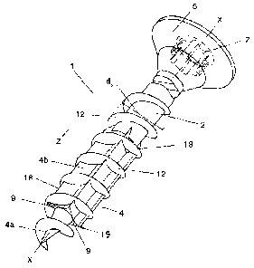
As is illustrated in the figures, a screw element 1 according to the invention
comprises
a threaded shank 2 and a screw tip 4 which is configured on one end of the
former, and a
screw head 5 which is on an end which is opposite to the screw tip 4 and which
has a force
application means 7 for a screwing tool. The screw head 5 may be configured
as, for
example, a countersunk head, a round head or a flat head. The screw head 5 may
also be
shaped as a cylindrical extension of the threaded shank 2. The force
application means 7
may be configured as a slot, a cross slot or as a socket force application
means, for example
in the form of a hexagonal socket or of a star socket or also, for example, as
a hexagonal
head on the screw head 5.
A screw thread 12 runs on the threaded shank 2 and on the screw tip 4. The
thread is
preferably formed by a thread turn 13 which runs in a helical shape and which,
in the cross
section, is configured to be triangular, for example, cf. Figs. 7, 8. It is
also within the scope of
the invention for the thread 12 according to the invention to be configured as
a multi-turn
thread, for example consisting of two thread turns which are of helical shape
and arranged in
a circumferentially offset manner.
CA 02852286 2014-05-23
-6-
The screw thread 12 according to the invention is advantageously configured as
a
self-tapping or self-forming thread, respectively. The thread 12 according to
the invention
may have a constant thread lead, or else a variable thread lead, over the
entire thread
region. The thread 12 according to the invention has a maximum thread diameter
dg, i.e. the
nominal diameter of the screw element according to the invention, which, in
the illustrated
exemplary embodiment, is constant in the region of the threaded shank, so that
no change in
the thread diameter is present in this region. The thread lead of the screw
thread according
to the invention is preferably 40% to 70% of the nominal diameter dg of the
screw thread
according to the invention, and specifically in relation to a single-turn
thread..
According to the invention, the screw tip 4 is composed of two tip portions 4a
and 4b,
and specifically, when viewed in the screw-in direction Z, of the front first
tip portion 4a which
tapers off towards the end of the screw element, and of the second tip portion
4b, which is
adjacent to said first tip portion 4a. The tip portion 4b, when viewed in the
cross section
perpendicular to a central longitudinal axis X-X, has a polygonal cross
section of its core
having an enveloping circle 14 having a diameter dm, which runs through its
polygon corners,
cf. Fig. 3b. The first tip portion 4a is preferably configured as a pointed
cone, as illustrated in
Fig. 1, wherein its cone angle a may be 100 to 400, in particular 20 , cf.
Fig. 3. The conical
first tip portion 4a, in relation to the central longitudinal axis X-X, has a
perpendicularly
running circular cross section. The screw thread 12 runs over the entire
threaded tip 4,
wherein its radial thread height decreases to zero up to the end of the
conical portion 4a. In
the region of the second tip portion 4b which is of polygonal cross-sectional
shape, the
thread 12 preferably runs at a constant thread height, so that, also in the
region of the tip
portion 4b, the thread 12 has the nominal thread diameter dg, as in the region
of the threaded
shank 2. The enveloping circle 14 of the polygonal tip portion 4b is larger
than the core
diameter dk of the screw core in the region of the tip portion 4a, cf. Fig. 3.
According to the
invention, on the transition between the first tip portion 4a and the second
tip portion 4b, at
least one end edge face 9 which, in relation to the longitudinal centre axis X-
X, is radially
oriented, specifically in the sense of a diameter enlargement, and which
terminates in a
vertex 15 of the polygonal cross section, which lies on the enveloping circle
of the second tip
portion 4b, is present. This radially running end edge face 9 forms a type of
cutting edge or
milling edge, respectively. In the illustrated exemplary embodiment, the
polygonal cross
section of the second tip portion 4b has four vertices 15, so that the four
end edge faces 9
are configured, specifically in relation to the circumference of the screw
element 1 according
CA 02852286 2014-05-23
=
-7-
to the invention, cf. Fig. 2. As can be seen in particular in Fig. 1, the
screw thread 12 runs
without interruption over the first and second tip portions 4a, 4b, so that
the screw thread 12
is also configured in the region of the end face edges 9. In Fig. 2, in which
only the screw
core of the screw element 1 according to the invention is illustrated,
specifically the screw
core in the region of the threaded shank 2 and in the region of the threaded
tip 4, the
configuration of the end face edge 9 is clearly visible in the transition from
the first tip portion
4a to the second tip portion 4b. Here, the end face edges 9 run radially in
relation to the
longitudinal axis X-X. The enveloping circle of the second tip portion 4b
advantageously has
a diameter dh which is larger than/equal to a maximum core diameter ds of the
threaded
shank 2 which is circular in cross section. It is of advantage here for the
enveloping circle
diameter of the second tip portion 4b, which is polygonal in its cross
section, to be constant
over its axial length. As can be seen from the individual figures, the
diameter of the pointed
conical first threaded portion 4a, on its base face in the transition between
the first and the
second tip portions 4a, 4b, is smaller than the maximum core diameter ds of
the threaded
shank 2. It is furthermore provided according to the invention that the screw
thread 12, in the
region of the second tip portion 4b and likewise on the shank portion 2, has a
larger outer
diameter dg than the maximum enveloping circle diameter dh of the polygonal
tip portion 4b.
In the illustrated exemplary embodiment, the thread 12 runs over the entire
length of
the threaded shank 2. It is likewise within the scope of the invention for the
thread 12 not to
run over the entire length of the threaded shank 2, but for there to be a
thread-free shank
portion to be configured, for example between the threaded portion of the
threaded shank 2
and the screw head 5, such that only a part-thread is present on the threaded
shank 2.
Furthermore, it may be of advantage, according to the invention, for the part-
length of
the first tip portion 4a to be in the range of a minimum of 0.8 times to a
maximum of 2.0 times
the lead s of the thread 12.
As can be seen in particular from Figs. 3a to 3c and 4 to 6, the second tip
portion 4b,
in its cross section, is configured in a polygonal manner such that it forms a
quadrangle
having four vertices 15. It is expedient here for the four vertices 15 to lie
in each case on
intersecting straight lines gi, g2, running orthogonally to the central
longitudinal axis X-X, of
the polygonal cross section, and in each case to be at the same distance b
from the
longitudinal axis X-X. It is expedient here, according to the invention, when
viewed in the
cross section, if the core sides 22 connecting the vertices 15 are configured
so as to be
concave, as can be seen, in particular, in Fig. 6. The core sides 22 may also
run in a straight
CA 02852286 2014-05-23
-8-
line. In the illustrated exemplary embodiments, a quadrangle is illustrated as
the polygonal
cross section of the tip portion 4b, but, likewise according to the invention,
a triangular cross
section or a cross section which has more than four corners may also be
selected. It is
preferred for a regular cross section to be configured. The vertices 15 of the
individual cross
sections, which lie behind one another in the longitudinal direction of the
tip portion 4b, which
is polygonal in its cross section, lie on straight lines which are parallel to
the central
longitudinal axis X-X, so that straight core edges 18 are formed and may thus
have an
additional milling effect, if a resilience of the material into which the
screw element 1
according to the invention is screwed arises. As is illustrated in Fig. 6, the
polygonal
quadrangular cross section of the tip portion 4b may in each case be
configured to be
symmetrically folding about the orthogonal straight lines gi, g2. A shape
which deviates
therefrom is illustrated in Fig. 4, wherein the core sides 22 and/or the core
side faces of the
entire portion resultant therefrom are configured in such a manner that an
asymmetry results
in relation to the orthogonal straight lines gl, g2. A design is shown in Fig.
4, in which the side
portions or face portions, respectively, which point towards the turning
direction and which
originate from the respective vertex 15 and/or the core edges 18, run radially
steep in the
direction towards the longitudinal axis X-X in such a manner that they enclose
an acute angle
6 < 20 with the respective straight line running through the vertex 15 and,
adjacent thereto,
run in an almost straight line to that vertex 15 which follows in the turning
direction. In Fig. 4,
a shape of this type according to the invention for a clockwise turning
direction D is
illustrated, and in Fig. 5, a corresponding shape with the turning direction D
being counter-
clockwise is illustrated. In Figs. 3 to 3c, a polygonal cross-sectional shape
of the tip portion
4b, corresponding to Fig. 4, is illustrated. A corresponding cross-sectional
shape of the
polygonal tip portion 4b is also selected in Figs. 7 and 8. On account of the
configuration of
the polygonal cross section according to Figs. 4 and 5, an improved cutting
effect and/or
milling effect of the cutting edges 18 is achieved, which applies to the
embodiment according
to Fig. 4. In the embodiment according to Fig. 5, the effect is accordingly
that in the case of a
turning direction D, which is present when subjecting a screw according to the
invention to
rotation when loosening, loosening is met with a higher resistance.
In Figs. 9 and 10 a design of a screw element 1 according to the invention,
which
substantially corresponds in a corresponding manner to the screw element 1
according to
Figs. 1 to 8 is illustrated, wherein, however, there is one difference in that
the enveloping
circle diameter dh of the enveloping circle 14 of the polygonal tip portion 4b
is not constant
CA 02852286 2014-05-23
=
=
-9-
and not of the same size over the entire length of the tip portion 4b, but
that the enveloping
circle diameter dh, commencing with a diameter dhl in the region of the end
edge faces 9,
becomes larger, specifically preferably continuously larger, towards the
threaded shank 2, up
to the maximum enveloping circle diameter dh2 in the remaining region of the
polygonal tip
portion 4b. Here, the length over which an increase of the enveloping circle
diameter dh up to
the maximum diameter takes place is preferably 10% to 50% of the entire length
of the
polygonal tip portion 4b. The difference in diameter between the enveloping
circle diameter
dhi in the region of the end face edge 9 and the maximum enveloping circle
diameter dh2 in
the region of the polygonal tip portion 4b, in which a constant enveloping
circle diameter dh2
is present, is 5% to 20% of the maximum enveloping circle diameter dn.
As illustrated in the individual figures, in the screw element 1 according to
the
invention the outer thread edge of the thread 12, in the region of the
threaded shank 2 and
also over the polygonal tip portion 4b, runs at a constant radius and a
constant thread height.
Over the region of the tip portion 4a in the shape of a truncated cone and up
to the end of the
same, the thread turn 13 runs helically and with a radius which continuously
decreases to
zero and with a decreasing thread height.
In one advantageous design which is not illustrated in the drawings, the
thread edge
of the thread 12, at least in the region of the threaded portion 4 and
simultaneously in the
region of the flank face of the thread, may moreover be configured in a
wavelike manner
such that a sequence of wave crests and wave troughs is present. Here,
reference is made
in full to document DE 3335092 A1.
The invention is not limited to the illustrated and described exemplary
embodiments,
but also comprises all implementations having the same effect according to the
concept of
the invention. It is expressly emphasized that the exemplary embodiments are
not limited to
all features in combination with one another; far rather, each individual sub-
feature in its own
right, also separately from all other sub-features, may be of inventive
significance.
Furthermore, the invention hitherto is also not limited to the combination of
features defined
in any single claim, but may also be defined by any other combinations of
specific features of
all collectively disclosed individual features. This means that, in principle,
practically any
individual feature of a given claim may be omitted and/or replaced by at least
one individual
feature that has been disclosed in another part of the application.
CA 02852286 2014-05-23
List of reference numerals:
1 Screw element
2 Threaded shank
4 Screw tip
4a Tip portion
4b Tip portion
4 Screw head
7 Force-application means
9 End edge face (end face edge)
12 Screw thread
13 Thread turn
14 Enveloping circle
Vertices
15 18 Core edges (cutting edges)
22 Core sides
Distance
Turning direction
dg Thread diameter
dh Diameter of the enveloping circle
dhl Diameter of the enveloping circle
dh2 Diameter of the enveloping circle
dk Core diameter of 4a
d, Maximum core diameter of the threaded shank 2
gl Orthogonal straight lines
92 Orthogonal straight lines
X-X Central longitudinal axis
Screw-in direction