Language selection

Search

Patent 2852420 Summary

Third-party information liability

Some of the information on this Web page has been provided by external sources. The Government of Canada is not responsible for the accuracy, reliability or currency of the information supplied by external sources. Users wishing to rely upon this information should consult directly with the source of the information. Content provided by external sources is not subject to official languages, privacy and accessibility requirements.

Claims and Abstract availability

Any discrepancies in the text and image of the Claims and Abstract are due to differing posting times. Text of the Claims and Abstract are posted:

  • At the time the application is open to public inspection;
  • At the time of issue of the patent (grant).
(12) Patent: (11) CA 2852420
(54) English Title: TRIP MECHANISM AND ELECTRICAL SWITCHING APPARATUS INCLUDING A TRIP MEMBER PUSHED BY PRESSURE ARISING FROM AN ARC IN AN ARC CHAMBER
(54) French Title: MECANISME DECLENCHEUR ET APPAREIL DE COMMUTATION ELECTRIQUE COMPORTANT UN ELEMENT DECLENCHEUR POUSSE PAR LA PRESSION PRODUITE PAR UN ARC DANS UNE CHAMBRE D'ARCHAMBRE A ARC
Status: Granted
Bibliographic Data
(51) International Patent Classification (IPC):
  • H01H 9/34 (2006.01)
  • H01H 71/12 (2006.01)
  • H01H 71/24 (2006.01)
  • H01H 77/02 (2006.01)
(72) Inventors :
  • SHEA, JOHN J. (United States of America)
  • SCHALTENBRAND, BRIAN J. (United States of America)
  • JANUSEK, MARK A. (United States of America)
(73) Owners :
  • EATON INTELLIGENT POWER LIMITED (Ireland)
(71) Applicants :
  • EATON CORPORATION (United States of America)
(74) Agent: BERESKIN & PARR LLP/S.E.N.C.R.L.,S.R.L.
(74) Associate agent:
(45) Issued: 2019-02-05
(86) PCT Filing Date: 2012-08-21
(87) Open to Public Inspection: 2013-06-13
Examination requested: 2017-08-10
Availability of licence: N/A
(25) Language of filing: English

Patent Cooperation Treaty (PCT): Yes
(86) PCT Filing Number: PCT/US2012/051655
(87) International Publication Number: WO2013/085578
(85) National Entry: 2014-04-15

(30) Application Priority Data:
Application No. Country/Territory Date
13/312,364 United States of America 2011-12-06

Abstracts

English Abstract

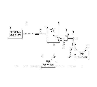
An electrical switching apparatus (2;50) includes separable contacts (10), an operating mechanism (16) structured to open and close the separable contacts, and a trip mechanism (14) cooperating with the operating mechanism to trip open the separable contacts. The trip mechanism includes a trip latch (4), and an arc chamber (18) operatively associated with the separable contacts. The arc chamber includes a plurality of arc plates (20) and a barrier (22) disposed between the arc plates and the trip latch. The barrier has an opening (12;58) therein. A trip member (8) is disposed in or about the opening of the barrier of the arc chamber. During interruption of current flowing through the separable contacts, pressure arising from an arc (11) in the arc chamber pushes the trip member away from the barrier of the arc chamber to engage the trip latch and cause the trip mechanism to trip open the separable contacts.


French Abstract

L'invention concerne un appareillage de commutation électrique (2; 50) comprenant des contacts séparables (10), un mécanisme d'actionnement (16) structuré pour ouvrir et fermer les contacts séparables, et un mécanisme de déclenchement (14) coopérant avec le mécanisme d'actionnement pour ouvrir par déclenchement les contacts séparables. Le mécanisme de déclenchement comprend un loquet de déclenchement (4) et une chambre à arc (18) associée de manière fonctionnelle aux contacts séparables. La chambre à arc comprend une pluralité de plaques à arc (20) et une barrière (22) disposée entre les plaques à arc et le loquet de déclenchement. La barrière possède une ouverture (12; 58). Un élément de déclenchement (8) est disposé à l'intérieur ou proche de l'ouverture de la barrière et de la chambre à arc. Durant l'interruption de l'écoulement du courant circulant à travers les contacts séparables, la pression provenant d'un arc (11) dans la chambre à arc pousse l'élément de déclenchement à distance de la barrière de la chambre à arc pour engager le loquet de déclenchement et provoquer l'ouverture par déclenchement des contacts séparables par le mécanisme de déclenchement.

Claims

Note: Claims are shown in the official language in which they were submitted.


- 8 -
What is claimed is:
1. An electrical switching apparatus comprising:
separable contacts;
an operating mechanism structured to open and close said separable
contacts;
a trip mechanism cooperating with said operating mechanism to trip open
said separable contacts, said trip mechanism comprising a trip latch;
an arc chamber operatively associated with said separable contacts, said
arc chamber comprising a plurality of arc plates and a barrier disposed
between
said arc plates and said trip latch, said barrier having an opening therein;
and
a trip member disposed in or about the opening of the barrier of said arc
chamber,
wherein during interruption of current flowing through said separable
contacts, pressure arising from an arc in said arc chamber pushes said trip
member away from the barrier of said arc chamber to engage the trip latch and
cause said trip mechanism to trip open said separable contacts;
wherein said trip member comprises a spring structured to return said trip
member to a seated position within the opening of said barrier after
interruption of
said current flowing through said separable contacts, a first portion having a

shape guided by the opening, a second portion having a recess accepting an end

of said spring, and a third portion offset from the first portion and
extending from
the second portion; and
wherein gas pressure arising from the arc in said arc chamber pushes said
first portion along the opening to cause the third portion to engage said trip
latch
lever.
2. The electrical switching apparatus of claim 1 wherein said opening is a
cylindrical opening; wherein said trip member is a cylindrical piston slidably

positioned within said cylindrical opening; and wherein gas pressure arising
from
the arc in said arc chamber pushes said cylindrical piston along the
cylindrical
opening to engage the trip latch.

- 9 -
3. The electrical switching apparatus of claim 2 wherein during flow of
said
current through said separable contacts, a mechanical load on said trip latch
increases from magnetic forces generated on said operating mechanism by said
flow of said current; and wherein said cylindrical piston is structured to
overcome
said mechanical load.
4. The electrical switching apparatus of claim 1 wherein said trip
mechanism
further comprises a trip solenoid and a trip circuit structured to sense the
current
flowing through said separable contacts and energize the trip solenoid; and
wherein said trip solenoid comprises a plunger structured to engage said trip
latch
and cause said trip mechanism to trip open said separable contacts.
5. The electrical switching apparatus of claim 1 wherein said separable
contacts comprise a fixed contact and a movable contact; wherein said
operating
mechanism comprises a contact carrier carrying said movable contact; and
wherein prior to interruption of said current flowing through said separable
contacts a magnetic force arising from said current lifts the contact carrier
and
causes a mechanical load on said trip latch, which requires additional force
from
said trip member to cause said trip mechanism to trip open said separable
contacts.
6. The electrical switching apparatus of claim 1 wherein said trip member
is a
piston aligned with said trip latch; and wherein said piston includes a spring

structured to return said piston to a seated position within the opening of
said
barrier after interruption of said current flowing through said separable
contacts.
7. The electrical switching apparatus of claim 1 wherein said electrical
switching apparatus is a circuit interrupter.
8. The electrical switching apparatus of claim 7 wherein said circuit
interrupter
is a circuit breaker.

- 10 -
9. An electrical switching apparatus comprising.
separable contacts;
an operating mechanism structured to open and close said separable
contacts;
a trip mechanism cooperating with said operating mechanism to trip open
said separable contacts, said trip mechanism comprising a trip latch;
an arc chamber operatively associated with said separable contacts, said
arc chamber comprising a plurality of arc plates and a barrier disposed
between
said arc plates and said trip latch, said barrier having an opening therein;
and
a trip member disposed in or about the opening of the barrier of said arc
chamber,
wherein during interruption of current flowing through said separable
contacts, pressure arising from an arc in said arc chamber pushes said trip
member away from the barrier of said arc chamber to engage the trip latch and
cause said trip mechanism to trip open said separable contacts;
wherein said opening is a cylindrical opening; wherein said trip member
comprises a spring structured to return said trip member to a seated position
within the opening of said barrier after interruption of said current flowing
through
said separable contacts, a first portion having a cylindrical shape guided by
the
cylindrical opening, a second portion having a recess accepting an end of said

spring, and a third portion offset from the first portion and extending from
the
second portion; and wherein gas pressure arising from the arc in said arc
chamber pushes said first portion along the cylindrical opening to cause the
third
portion to engage said trip latch lever.
10. A trip mechanism for an electrical switching apparatus comprising
separable contacts, an operating mechanism structured to open and close said
separable contacts, and an arc chamber operatively associated with said
separable contacts, said arc chamber comprising a plurality of arc plates and
a
barrier, said trip mechanism comprising:
an opening in the barrier of said arc chamber;
a trip latch, said barrier being disposed between said arc plates and said
trip latch; and

- 11 -
a trip member disposed in or about said opening in the barrier of said arc
chamber,
wherein said trip mechanism cooperates with said operating mechanism to
trip open said separable contacts;
wherein during interruption of current flowing through said separable
contacts, pressure arising from an arc in said arc chamber pushes said trip
member away from the barrier of said arc chamber to engage the trip latch and
cause said trip mechanism to trip open said separable contacts;
wherein said opening is a cylindrical opening;
wherein said trip member comprises a spring structured to return said trip
member to a seated position within the opening of said barrier after
interruption of
said current flowing through said separable contacts, a first portion having a

cylindrical shape guided by the cylindrical opening, a second portion having a

recess accepting an end of said spring, and a third portion offset from the
first
portion and extending from the second portion, and
wherein gas pressure arising from the arc in said arc chamber pushes said
first portion along the cylindrical opening to cause the third portion to
engage said
trip latch lever.
11. A trip
mechanism for an electrical switching apparatus comprising
separable contacts, an operating mechanism structured to open and close said
separable contacts, and an arc chamber operatively associated with said
separable contacts, said arc chamber comprising a plurality of arc plates and
a
barrier, said trip mechanism comprising:
an opening in the barrier of said arc chamber;
a trip latch, said barrier being disposed between said arc plates and said
trip latch; and
a trip member disposed in or about said opening in the barrier of said arc
chamber, said trip member comprising:
a spring structured to return said trip member to a seated position within
the opening of said barrier after interruption of current flowing through said

separable contacts,
a first portion having a shape guided by the opening,

- 12 -
a second portion having a recess accepting an end of said spring, and
a third portion offset from the first portion and extending from the second
portion,
wherein gas pressure arising from the arc in said arc chamber pushes said
first portion along the opening to cause the third portion to engage said trip
latch
lever;
wherein said trip mechanism cooperates with said operating mechanism to
trip open said separable contacts; and
wherein during interruption of said current flowing through said separable
contacts, pressure arising from an arc in said arc chamber pushes said trip
member away from the barrier of said arc chamber to engage the trip latch and
cause said trip mechanism to trip open said separable contacts.

Description

Note: Descriptions are shown in the official language in which they were submitted.


- 1 -
TRIP MECHANISM AND ELECTRICAL SWITCHING APPARATUS INCLUDING
A TRIP MEMBER PUSHED BY PRESSURE ARISING FROM AN ARC IN AN
ARC CHAMBER
BACKGROUND
Field
The disclosed concept relates generally to electrical switching
apparatus and, more particularly, to electrical switching apparatus, such as
circuit
breakers. The disclosed concept also relates to trip mechanisms for electrical
switching apparatus.
Background Information
Electrical switching apparatus, such as circuit breakers, provide
protection for electrical systems from electrical fault conditions such as,
for
example, current overloads, short circuits, abnormal voltage and other fault
conditions. Typically, circuit breakers include an operating mechanism which
opens electrical contact assemblies to interrupt the flow of current through
the
conductors of an electrical system in response to such fault conditions as
detected, for example, by a trip mechanism, such as a trip unit.
Latches are an important part of electrical switching apparatus, such
as circuit breakers. A latch assembly typically includes three components: a
pivotable D-shaft, a latch plate and a latch shaft. The latch plate and the
latch
shaft are suitably joined together and the latch plate rotates about a
longitudinal
axis of the latch shaft. The D-shaft blocks or allows movement of the latch
plate
through a D-shaft slot when in a corresponding suitable axial position as the
D-
shaft rotates on its longitudinal axis. The latch shaft and the D-shaft both
rotate
about their respective longitudinal axes, which are disposed a fixed distance
apart. The latch assembly can only rotate when the D-shaft is suitably
oriented to
allow the latch plate to pass through the D-shaft slot. The D-shaft can
include a
number of arms for interface, for example, by a trip plunger of a trip
solenoid that
is energized in response to a trip condition, as detected by the trip unit
CA 2852420 2018-09-13

CA 02852420 2014-04-15
WO 2013/085578 PCT/US2012/051655
- 7 -
During an interruption event, the trip latch load is increased during
excessive cumin flow because Of magnetic forces generated on the operating
mechanism and the movable contact arms. These magnetic tbrces translate to the

operating mechanism and create the need for relatively higher trip latch
forces. For
example, sometimes the contact carrier can begin to open prior to the trip
unit tripping
the circuit breaker. In other words, the magnetic forces lift the contact
carrier and
require an additional latch force to trip open the operating mechanism. As a
result,
during a relatively high fault current, the trip solenoid must either have
sufficient
operating force to operate the trip latch lever, or the desired trip might be
delayed or
inhibited, which would be completely undesirable.
There is room for improvement in electrical switching apparatus.
There is also room for improvement in trip mechanisms tbr electrical
switching apparatus.
SUMMARY
These needs and others are met by embodiments of the disclosed
concept where a trip member is disposed in an opening of a barrier of an arc
chamber.
During interruption of current flowing through separable contacts, pressure
arising
froin an arc in die arc chamber pushes the trip member away from the barrier
of the
arc chamber to engage a trip latch and cause a trip mechanism to trip open the
separable contacts.
In accordance with aspects of the disclosed concept, an electrical
switching apparatus comprises: separable contacts; an operating mechanism
structured to open and don the. separable contacts; a trip mechanism
cooperating
with the operating mechanism to trip open the separable contacts, the trip
mechanism
comprising a trip latch; an arc chamber operatively associated with the
separable
contacts, the arc chamber comprising a plurality of arc plates and a barrier
disposed
between the arc plates and the trip latch, the barrier having an opening
therein; and a
trip member disposed in or about the opening of the barrier of the arc
chamber,
wherein during interruption of current flowing through the separable contacts,
pressure arising from an arc in the arc chamber pushes the trip member away
from the
barrier of the arc chamber to engage the trip latch and cause the trip
mechanism to trip
open the separable contacts.

CA 02852420 2014-04-15
WO 2013/085578 PCT/US2012/051655
- 3 -
The opening may be a cylindrical opening; the trip member may be
cylindrical piston slidablV positioned within the Cylindrical opening; and gas
pressure
may arise from the arc in the arc chamber and push the cylindrical piston
along the
cylindrical opening to engage the trip latch.
During flow of the current through the separable contacts, a
mechanical load on the trip latch may increase from magnetic forces generated
on the.
operating mechanism by the flow of the current; and the cylindrical piston may
be
structured to overcome the mechanical load,
The trip member may be a piston aligned with the trip latch; and the
piston may include a spring structured to return the piston to a seated
position within
the opening of the barrier after interruption of the current flowing through
the
separable contacts.
As another aspect of .the disclosed concept, a. trip mechanism is for an
electrical switching apparatus comprising separable contacts, an operating
mechanism
structured to open and close the separable contacts, and an arc chamber
operatively
associated with the separable contacts, the arc chamber comprising a plurality
of arc
plates and a barrier. The trip mechanism comprises: an opening in the barrier
of the
arc chamber; g trip latch, the barrier being disposed. between the arc plates
and the trip
latch; and a trip member disposed in or about the opening in the barrier of
the arc
chamber, wherein the trip mechanism cooperates with the operating mechanism to
trip
open the separable contacts, and wherein during interruption of current
flowing
through the separable contacts, pressure arising from an arc in the arc
.chamber pushes
the trip member away from the barrier of the arc chamber to engage. the trip
latch and
cause the trip mechanism to trip open the separable contacts.
BRIEF DESCRIPTION OF THE DRAWINGS
A full understanding of the disclosed concept can be gained from the
following description of the preferred embodiments when read in conjunction
with the
accompanying drawings in .which:
Figure I is a. block diagram ofa circuit interrupter including a trip latch
lever, an arc chamber and a trip member in a non-tripped position in
accordance with
embodiments of the disclosed concept.

CA 02852420 2014-04-15
WO 2013/085578 PCT/US2012/051655
- 4 -
Figure.2 is a block diagram of the Circuit interrupter of Figure 1. with the.
trip member and the trip latch lever in a tripped position.
Figure 3 is an isometric view of a circuit interrupter including a trip latch
lever and a trip member in a non-tripped position in accordance with another
embodiment of the disclosed concept.
Figure 4 is a relatively more detailed isometric view of the circuit
interrupter of Figure 3.
Figures 5 and 6 are isometric views of the trip member of :Figure 3.
Figure 7 is a vertical elevation cross sectional view of the circuit
interrupter of Figure 3 showing the trip member and the arc chamber thereof
DESCRIPTION OF THE PREFERRED EMBODIMENTS
As employed herein, the term "number shall mean one or an integer
greater than one (i.e. a plurality).
As employed herein, the statement that two or more parts are
"connected" or "coupled'''. together shall mean that the parts are joined
together either
directly or joined through one or more intermediate parts. Further, as
employed
herein, the statement that two or more parts are atiached" shall mean that the
parts
are joined together directly.
The disclosed concept is described in association with a circuit
breaker, although the disclosed concept is applicable to a wide range of
electrical
switching apparatus.
Referring to Figures 1. and 2, an electrical switching apparatus. such as a.
circuit interrupter (e.g., without limitation, the example
citcnit.breaker.2),.includes
trip latch, such as the example trip latch lever 4, an arc chamber 6 and a
trip member
shown in respective .non-tripped and tripped positions. During interruption of
current
flowing through separable contacts 10 of the circuit breaker 2, pressure
arising from an
arc 11 (Figure 2) in the arc chamber 6 pushes the trip member 8 through an
opening
1.2 of the arc chamber 6.to engage and rotate (e.g., without limitation,
clOckwise:with
respect to Figure 2) the trip latch lever 4 and cause a trip mechanism 14 to
trip open
the separable contacts 10.
As is conventional, the example circuit breaket.2 includes an operating.
mechanism 16 structured to open and close the separable contacts 10, and the
trip

CA 02852420 2014-04-15
WO 2013/085578 PCT/US2012/051655
- 5 -
mechanism 14 cooperating with the operating mechanism 16 to trip open the
Separable contacts 10. The trip mechanism 14 includes the trip latch lever 4.
The are
chamber 6 is operatively associated with .the separable contacts 10 and
includes a
plurality of arc plates (not shown, but see the arc chamber 62 and the
plurality of arc
plates 20 of Figure 7) and a barrier 22 disposed between the arc plates (not
shown)
and the trip latch lever 4.
In accordance with aspects of the disclosed concept, the barrier 22 has
the opening .12 therein and forms a. cylindrically shaped port 24. The trip
member 8,
which can have, for example and without limitation, a shape resembling a
piston, is
disposed in the port 24. The trip member 8 is suitably aligned with the trip
latch lever
4. During interruption of current flowing through the separable contacts 10,
gas
pressure 25 arising; from the arc 11 in the arc chamber 6 pushes the trip
member 8
away from the barrier 22 to engage the trip latch lever 4 and cause the trip
mechanism
14 to trip open the separable contacts 10. Preferably, a spring (not shown,
but see
spring 26 of Fi.{.tures 3 and 4) is employed to return the trip member 8 to a
seated (or
relaxed state) position as shown in :Figure 1 after the gas pressure 25 is
released,
As is also conventional, the trip mechanism 1.4 -further includes a trip
solenoid 2.8 and a trip circuit 30 structured to sense the current flowing
through the
separable contacts .10 and responsively energize the trip solenoid 28. The
trip
solenoid 28 includes a plunger 32 structured to engage the trip latch lever 4
and cause
the. trip mechanism 14 to trip open the separable contacts 10.
Figures 3 and 4 show another electrical switching apparatus, such as the
example circuit interrupter 50, including a trip latch lever .52 and a trip
member 54 in .a
non-tripped position. In this example, the trip member 54 is shaped like a
piston and is
suitably aligned with the trip latch lever 52. The trip .member 54 includes
the spring
26 structured to return the trip member 54 to a seated (or relaxed) position
Os shown
in Figures 3 and 4) within an example cylindrically shaped opening 58 of a
barrier 60
(Figure .7) Of an are chamber 62 (Figure 7) after interruption of current
flowing
through separable. contacts .64.
As shown in Figures 5 and 6, the trip member 54 includes a first portion
66 having a cylindrical shape (e.g., without limitation, shaped like a piston)
structured to
be guided by the cylindrically shaped opening 58, a second portion 68 having a
recess 70

- 6 - -
to accept one end 72 (shown in phantom line drawing in Figure 5; shown in
Figure
7) of the spring 26, and a third portion 74 offset from the first portion 66
and
extending from the second portion 68. The third portion 74 has an end 76 that
engages an arm 78 (Figures 3 and 4) of the trip latch lever 52 (Figures 3 and
4).
Figure 7 shows the trip member 54, the cylindrically shaped opening
58 and the arc chamber 62. The first portion 66 is slidably positioned within
the
cylindrically shaped opening 58. Gas pressure arising from an arc (not shown
but
see the arc 11 of Figure 2) in the arc chamber 62 pushes the cylindrically
shaped
first portion 66 along the cylindrically shaped opening 58 to engage the trip
latch
lever 52.
During flow of current through the separable contacts 64, a
mechanical load on the trip latch lever 52 increases from magnetic forces
generated on operating mechanism 80 by the flow of the current. The trip
member
54, as moved by the gas pressure arising from the arc in the arc chamber 62
against the force of the spring 26 (Figures 3, 4 and 7) is structured to
overcome
the increased mechanical load on the trip latch lever 52.
The separable contacts 64 include a fixed contact 82 and a movable
contact 84. The operating mechanism 80 includes a contact carrier 86 carrying
the
movable contact 84. Prior to interruption of the current flowing through the
separable contacts 64, a magnetic force arising from the current lifts the
contact
carrier 86 and causes a mechanical load on the trip latch lever 52, which
requires
additional force from the trip member 54 to cause a trip mechanism 88, when
released by the trip latch lever 52, to trip open the separable contacts 64.
A non-limiting example of a circuit breaker including a 0-shaft, which
can be rotated by the disclosed trip latch lever 52, and a latch mechanism is
disclosed by U.S. Patent Application Publication No. 2011/0062006.
The disclosed arc pressure assisted trip members 8,54 preferably
provide sufficient tripping force to independently ensure that the
corresponding
electrical switching apparatus 2,50 does trip.
While specific embodiments of the disclosed concept have been
described in detail, it will be appreciated by those skilled in the art that
various
modifications and alternatives to those details could be developed in light of
the
CA 2852420 2017-08-10

CA 02852420 2014-04-15
WO 2013/085578
PCT/US2012/051655
- 7 -
overall teachings of the disclosure. Accordingly; the particular .arrangements

disclosed are meant to be illustrative only and not limiting as to the scope
of the
disclosed concept which is to be given the full breadth of the claims appended
and
any and all equivalents thereof.

Representative Drawing
A single figure which represents the drawing illustrating the invention.
Administrative Status

For a clearer understanding of the status of the application/patent presented on this page, the site Disclaimer , as well as the definitions for Patent , Administrative Status , Maintenance Fee  and Payment History  should be consulted.

Administrative Status

Title Date
Forecasted Issue Date 2019-02-05
(86) PCT Filing Date 2012-08-21
(87) PCT Publication Date 2013-06-13
(85) National Entry 2014-04-15
Examination Requested 2017-08-10
(45) Issued 2019-02-05

Abandonment History

There is no abandonment history.

Maintenance Fee

Last Payment of $263.14 was received on 2023-12-18


 Upcoming maintenance fee amounts

Description Date Amount
Next Payment if small entity fee 2025-08-21 $125.00
Next Payment if standard fee 2025-08-21 $347.00

Note : If the full payment has not been received on or before the date indicated, a further fee may be required which may be one of the following

  • the reinstatement fee;
  • the late payment fee; or
  • additional fee to reverse deemed expiry.

Patent fees are adjusted on the 1st of January every year. The amounts above are the current amounts if received by December 31 of the current year.
Please refer to the CIPO Patent Fees web page to see all current fee amounts.

Payment History

Fee Type Anniversary Year Due Date Amount Paid Paid Date
Application Fee $400.00 2014-04-15
Maintenance Fee - Application - New Act 2 2014-08-21 $100.00 2014-08-18
Maintenance Fee - Application - New Act 3 2015-08-21 $100.00 2015-07-14
Maintenance Fee - Application - New Act 4 2016-08-22 $100.00 2016-07-13
Maintenance Fee - Application - New Act 5 2017-08-21 $200.00 2017-07-14
Request for Examination $800.00 2017-08-10
Maintenance Fee - Application - New Act 6 2018-08-21 $200.00 2018-07-19
Final Fee $300.00 2018-12-13
Registration of a document - section 124 $100.00 2019-01-16
Maintenance Fee - Patent - New Act 7 2019-08-21 $200.00 2019-07-22
Maintenance Fee - Patent - New Act 8 2020-08-21 $200.00 2020-07-21
Maintenance Fee - Patent - New Act 9 2021-08-23 $204.00 2021-07-21
Maintenance Fee - Patent - New Act 10 2022-08-22 $254.49 2022-07-21
Maintenance Fee - Patent - New Act 11 2023-08-21 $263.14 2023-07-21
Maintenance Fee - Patent - New Act 12 2024-08-21 $263.14 2023-12-18
Owners on Record

Note: Records showing the ownership history in alphabetical order.

Current Owners on Record
EATON INTELLIGENT POWER LIMITED
Past Owners on Record
EATON CORPORATION
Past Owners that do not appear in the "Owners on Record" listing will appear in other documentation within the application.
Documents

To view selected files, please enter reCAPTCHA code :


To view images, click a link in the Document Description column. To download the documents, select one or more checkboxes in the first column and then click the "Download Selected in PDF format (Zip Archive)" or the "Download Selected as Single PDF" button.

List of published and non-published patent-specific documents on the CPD .

If you have any difficulty accessing content, you can call the Client Service Centre at 1-866-997-1936 or send them an e-mail at CIPO Client Service Centre.


Document
Description 
Date
(yyyy-mm-dd) 
Number of pages   Size of Image (KB) 
Abstract 2014-04-15 2 80
Claims 2014-04-15 2 171
Drawings 2014-04-15 5 273
Description 2014-04-15 7 581
Representative Drawing 2014-04-15 1 13
Cover Page 2014-06-17 1 52
Request for Examination / Amendment 2017-08-10 9 385
Claims 2017-08-10 5 189
Description 2017-08-10 7 454
Office Letter 2018-06-28 2 68
Amendment after Allowance 2018-09-13 2 89
Acknowledgement of Acceptance of Amendment 2018-09-20 1 50
Description 2018-09-13 7 454
Final Fee 2018-12-13 1 42
Representative Drawing 2019-01-10 1 8
Cover Page 2019-01-10 1 47
PCT 2014-04-15 4 107
Assignment 2014-04-15 5 136
Fees 2014-08-18 1 33