Note: Descriptions are shown in the official language in which they were submitted.
CA 02852559 2014-05-15
"MOTORCYCLE ENGINE HOIST"
FIELD OF THE INVENTION
The present invention relates generally to the field of engine hoist
devices and, more particularly, to an engine hoist apparatus for removing,
performing work on and reinstalling an engine of a motorcycle.
BACKGROUND OF THE INVENTION
The background information discussed below is presented to better
illustrate the novelty and usefulness of the present invention. Except where
indicated, this background information is not admitted prior art.
One of the biggest issues for motorcycle enthusiasts and motorcycle
mechanics, when servicing or rebuilding their engines, is getting the heavy
engines
out of the motorcycles. Motorcycle engines commonly weigh as much as 250 lbs
or
more. Often, a motorcycle owner's manual states that it takes three (3) men to
lift a
motorcycle engine out from the motorcycle's frame. Conventional automotive
engine floor hoists are not suitable for motorcycle engines because such
hoists are
designed to remove engines upward out of the automobile's engine compartment.
In the case of motorcycles, engines cannot be moved upwards, because that
direction is blocked by the motorcycle's frame, gas tank and seat. Moreover,
in
most motorcycles, there is typically only a few inches of clearance between
the top
of the engine and motorcycle's frame portion that is located above the engine.
As
CA 02852559 2014-05-15
such, motorcycle engines are generally removed from the motorcycle in a
generally
lateral fashion.
In cases where one cannot find additional manpower to lift an engine
out of a motorcycle, a popular way to accomplish removal of the engine alone
is as
follows. First, the various components and parts are removed from the
motorcycle
as much as possible, to lighten the overall motorcycle. Then the engine/motor
mounts are removed or loosen. The motorcycle is then slowly tilted on its
side,
allowing the engine to gently rest on the floor or ground surface. Once the
engine is
supported by the ground, the motorcycle and its frame are lifted back up,
thereby
.. leaving the engine supported by the ground surface and free to work on.
However,
this practice is time consuming (especially the first part of removing various
components and parts from the motorcycle), risks damaging the engine and
motorcycle during the tilting stage, such as if the motorcycle is accidentally
dropped
on its side and creates safety concerns (such as being pinned or trapped
underneath the motorcycle).
Therefore, what is needed is an apparatus, device or assembly to
easily, reliably and safely move a motorcycle engine in and out of its frame.
2
CA 02852559 2014-05-15
BRIEF DESCRIPTION OF THE DRAWINGS
Referring to the drawings, several aspects of the present invention are
illustrated by way of example, and not by way of limitation, in detail in the
figures,
wherein:
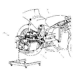
FIG. 1 is a perspective view of a preferred embodiment of the
invention, shown adjacent a motorcycle;
FIG. 2 is a perspective view of the embodiment of FIG. 1;
FIG. 3 is a perspective view of portions of the embodiment of FIG. 1,
illustrating pivotal movement of the first section relative to the second
section;
FIGS. 4a ¨ 4c are perspective views of the lower portions of
embodiment of FIG.1, illustrating the different orientations of the jack base
member;
FIGS. 5 ¨ 7 are perspective views of the embodiment of FIG. 1 being
utilized to lift and remove an engine from a motorcycle;
FIGS. 8 ¨ 9 are perspective views of the embodiment of FIG. 1 with an
optional tray attachment;
FIG. 10 is a perspective view of the interior of the sliding member of
the embodiment of FIG. 1 (receiver portion not shown), illustrating the
rollers
disposed within;
FIG. 11a is a perspective view of another embodiment of the
invention;
FIGS. llb ¨11c are close-up perspective views of the lifting means of
the embodiment of FIG. 11a;
3
CA 02852559 2014-05-15
FIG. 12 is a perspective view of portions of the embodiment of FIG.
11a, illustrating pivotal movement of the first section relative to the second
section;
FIGS. 13a ¨13b are close-up perspective views of the sliding member
of the embodiment of FIG. 11a; and
FIG. 14 is a perspective view of roller pins, roller pin bearings and
bearing retaining bushing of the embodiment of FIG. 11a.
DETAILED DESCRIPTION OF THE PREFERRED EMBODIMENTS
The following description is of preferred embodiments by way of
example only and without limitation to the combination of features necessary
for
carrying the invention into effect. Reference is to be had to the Figures in
which
identical reference numbers identify similar components. The drawing figures
are
not necessarily to scale and certain features are shown in schematic or
diagrammatic form in the interest of clarity and conciseness.
In accordance with a preferred embodiment of the present invention,
and as shown generally in Figures 1-10, there is a provided an engine hoisting
assembly 10 for supporting, lifting and lowering an engine E as may be
desired.
Engine hoisting assembly 10 is preferably for use with a vehicle such as a
motorcycle M wherein engine E is mounted within the motorcycle's frame F.
Although the assembly 10 is illustrated for use with a motorcycle M, the
assembly
10 will work equally well with other types of vehicles wherein an engine is
typically
4
CA 02852559 2014-05-15
moved laterally out of the vehicle's frame. For example, the assembly 10 will
work
with garden tractors, tricycles, quads and even riding lawn mowers.
In the preferred embodiment the engine hoisting assembly 10
comprises a ground supporting frame 12, a substantially vertical or upright
member
or post 14 having a longitudinal axis LA, a substantially horizontal member or
boom
16 operably connected to upright member, lifting means 40 to selectively move
boom 16 up or down and engine connecting means 50 to operably connect boom
16 to, and support therefrom, an engine E. Preferably, boom 16 is an elongate
member with a longitudinal axis L having two ends 16a, 16b, wherein one end
16a
is operably connected to upright member 14 and the other end 16b can be easily
inserted, at least partially, within motorcycle engine frame F above engine E
(see
FIG. 5). More preferably, boom 16 is of sufficient length (i.e. has a
sufficiently long
longitudinal axis L) so that, when positioned within frame F above at least a
portion
of the engine E, it extends completely over top of said engine E from one
lateral
side of the engine E to the other side. Preferably, the boom 16 has a length
in the
range of 18 to 36 inches. More preferably, and for typical motorcycle engine
as
illustrated in the figures, boom 16 has a length in the range of 26 to 32
inches.
Advantageously, with a boom 16 sufficiently long to extend over substantially
all of
engine E from one side to the other, it will be easier to use engine
connecting
means 50 to support the engine E from the boom 16. More advantageously, by not
making boom 16 excessively long, the assembly 10 will be easy to move and
manipulate into position adjacent the motorcycle M.
5
CA 02852559 2014-05-15
As can be seen in the figures of the preferred embodiment, ground
supporting frame 12 supports upright member 14, which projects substantially
vertically therefrom. Ground supporting frame 12 preferably has a forked base
12b
and a plurality of wheels or casters 12w to facilitate mobility of the engine
hoisting
assembly 10. In the preferred embodiment of Figures 1-10, one end 16a of the
boom 16 is slidably mounted to upright member 14 for slidable movement
therealong and boom 16 is maintained at a substantial horizontal orientation
when
lifting means 40 selectively moves boom 16 (see FIGS. 5 ¨ 6). Advantageously,
by
keeping boom 16 at a substantial horizontal orientation, free end 16b of boom
16
can be easily inserted into, and moved within, motorcycle engine frame F above
engine E without jamming against a portion of the frame F or engine E, as is
the
case with traditional engine hoists wherein the boom element pivots at one
end. In
other embodiments (not shown), boom 16 may be operably connected to upright
member in some other fashion, such as through a linkage, wherein the
longitudinal
axis L of boom 16 is maintained at a substantial horizontal orientation when
lifting
means 40 selectively moves boom 16 up or down.
In the preferred embodiment of Figures 1-10, engine connecting
means 50 comprises at least one tensile member, such as an adjustable strap 52
having D-rings 52d. In other embodiments (not shown), the engine connecting
means 50 comprises a ratchet strap or a metal chain. Engine connecting means
50
operably connect boom 16 to engine E so as to allow boom 16 to carry and
support
the full weight of the engine E, such as by having said one or more adjustable
straps 52 wrap around select portions of the engine E and also connect to, or
warp
6
CA 02852559 2014-05-15
around boom 16 (see, for example, FIGS. 5 ¨ 7). Preferably, adjustable straps
52
are substantially flat, to facilitate use of said straps 52 to connect engine
E to boom
16 in tight space constraints that may be present when engine E is within
frame F.
Advantageously, the assembly 10 of the embodiment of FIGS. 1-10 allows for
connection to a motorcycle engine E, even when there are only a few inches of
clearance between the top of the engine E and motorcycle's frame F.
Preferably, the various components of the invention 10, such as the
base 12, upright member 14 and boom 16, are made of metal, steel or any other
suitable material that provides adequate strength, durability and rigidity to
support
the various loads that may be encountered by the engine hoisting assembly 10.
Upright member 14 may be welded to base 12 or fastened to base 12 in another
suitable conventional manner.
In the preferred embodiment of Figures 1-10, upright member 14 has
an upper end 14u and a lower end 141, with lower end being supported by frame
12.
Boom 16 is slidably mounted to upright member 14 for slidable movement
therealong, i.e. between upper and lower ends 14u, 141. Preferably, boom 16 is
slidably mounted to upright member 14 via a sliding member 18. More
preferably,
sliding member 18 further comprises receiver portion 18r to receive one end
16a of
boom 16 therein. Even more preferably, a removable retaining pin 18p and
corresponding orifices 18ro, 16ro through receiver portion 18r and end 16a are
provided for secure location of the boom 16 within the receiver portion 18r in
a
conventional manner. Advantageously, by utilizing a receiver portion 18r,
booms of
7
CA 02852559 2014-05-15
different sizing and shapes may be interchanged onto sliding member 18 (see,
for
example, boom 16' in FIG. 9). More advantageously, by utilizing a receiver
portion
18r, boom 16 may be removed from assembly 10 so as to allow assembly 10 to
disassemble for more compact storage or shipping. In other embodiments (not
.. shown), boom 16 may be welded to sliding member 18 or fastened to said
member
18 in another suitable conventional manner.
Sliding member 18 has a central passage 19 through which upright
member 14 may pass (see FIGS. 2 and 10). Preferably, central passage 19, has a
central passage axis CA to slidably receive upright member therealong. Sliding
member 18 preferably has a plurality of bearings, bushings or rollers 20
disposed
within central passage 19 to rollably receive upright member therebetween and
facilitate sliding movement of sliding member 18 along the upright member 14.
Advantageously, rollers 20 facilitate sliding movement of the sliding member
18 and
boom 16 when the assembly 10 is loaded with the weight of an engine E.
Preferably, there are four rollers 20 disposed within central passage 19 in a
pair-
wise arrangement, with an upper pair 20a, 20b positioned substantially above
lower
pair 20c, 20d, as more clearly shown in FIG. 10. More preferably, rollers 20
are
removably secured in proper placement within central passage 19 by removable
roller retaining pins 22 insertable through sliding member 18 via paired
corresponding sliding member orifices 18oa, 18ob, 18oc, 18od, said rollers 20
preferably having an internal passage of suitable diameter to accept a
retaining pin
22 therethrough. Alternatively, in another embodiment (not shown), retaining
pins
22 may incorporate roller, bushing or bearing components within them.
8
CA 02852559 2014-05-15
Advantageously, rollers 20 may be removed for servicing by pulling pins 22
from
sliding member 18. More advantageously, the angle of sliding member 18,
relative
to upright member 14, and any boom 16 attached thereto, may be adjusted by
pulling or removing one or more of the retaining pins 22 (see FIG. 3 for
example).
Preferably sliding member securing means 30 are provided to
securely maintain sliding member 18 (and hence boom 16 and any load carried by
boom) at one or more desired preset locations vertically along upright member
14.
In the preferred embodiment of the assembly 10, securing means 30 comprises:
(i)
a plurality of upright member orifices 140 positioned at regular intervals
along
upright member 14, substantially between upper and lower end 14u, 141 (see
FIG.
2), (ii) a central orifice 18o having an axis A2 through substantially the
center of
sliding member 18 and (iii) a removable security retaining pin 32. The
plurality of
orifices 14o positioned at regular intervals along upright member 14
substantially
correspond to the desired preset locations. The plurality of orifices 14o
preferably
have an axis Al that is substantially perpendicular to the longitudinal axis
LA of the
upright member 14 (e.g. see FIG. 12). Sliding member 18 may be retained at a
desired preset location along upright member 14 by aligning central orifice
180 with
one of the orifices 14o (and preferably by also aligning axis Al with axis A2)
in
upright member 14 and then placing removable retaining pin 32 through both
orifices 14o, 18o to selectively and securely maintain the sliding members 18
position along (see, for example, FIG. 3). Advantageously, in addition to
securely
maintain sliding member 18 (and hence boom 16) at one or more preset locations
9
CA 02852559 2014-05-15
vertically along upright member 14, retaining pin 32 can also function as a
pivot pin
for sliding member 18 and boom 16 when retaining pins 22 and rollers 20 are
removed (see FIGS. 3, 11a, 11 b and 12 for example).
Preferably, lifting means 40 further comprises a jack 42 and a jack
base member 44. Jack base member 44 supports jack 42 and is selectively,
securably positionable along upright member 14 at one or more desired preset
locations vertically along upright member 14 (see, for example FIG. 5 where
jack 42
and jack base member 44 are positioned near the upper end 14u of upright
member
14). Advantageously, lifting means 40 may be quickly positioned along upright
member 14 at a desired vertical location; e.g. a location that substantially
corresponds to a vertical location where boom 16 will be positioned above an
engine E of a particular motorcycle M or other vehicle. Jack 42 is illustrated
as a
scissor-type jack, but jack could also be another type of suitable jack, such
as a
hydraulic jack. In another embodiment (not shown), jack 42 may be hydraulic
cylinder-type jack mounted directly to jack base member 44 (rather than merely
being supported by jack base member 44).
Jack 42 and jack base member 44 cooperate to selectively move
boom 16 up or down along upright member 14. In the preferred embodiment of
FIGS. 1-10, jack 42 and jack base member 44 are disposed along upright member
14 at a position below boom 16 and sliding member 18, with jack 42 engaging a
lower surface of boom 16 (or of sliding member 18) at an interface IF (see
FIGS. 5 ¨
9). Preferably the interface IF is between jack 42 and a lower surface of the
CA 02852559 2014-05-15
receiver portion 18r of sliding member 18 (see FIGS. 8-9). Jack 42 may be
actuated in a conventional manner to raise (or lower) boom 16 and/or sliding
member 18 ¨ compare FIG. 5 to FIG. 6 which illustrate jack 42 raising sliding
member 18, boom 16 and engine E attached to boom (the raising action being
indicated by arrows labeled U). Advantageously, jack 42 may be actuated to
selectively move boom 16 and/or sliding member 18 so as to: (i) make fine
adjustments to boom's location above engine E in a particular motorcycle M
and/or
(ii) lift engine E from the frame F once boom 16 is connected to engine using
the
engine connecting means 50 (see FIG. 6). More advantageously, by having jack
42
engage at sliding member 18 (and, hence, also at boom 16 adjacent end 16a),
and
by having sliding member 18 slide along upright member 14 via rollers 20
disposed
in central passage 19, boom 16 is maintained at a substantial horizontal
orientation
when lifting means 40 selectively moves boom 16 along upright member 14.
In the preferred embodiment of the assembly 10, jack base member
44 may be secured at a desired preset location via jack base securing means
43.
In the preferred embodiment of FIGS. 1 ¨ 10, jack base securing means
comprises
(i) the plurality of upright member orifices 14o positioned at regular
intervals along
upright member 14, (ii) one or more base member orifices 440 through the jack
base member 44 and (iii) a base member retaining pin 44p. The plurality of
orifices
140 positioned at regular intervals along upright member 14 substantially
correspond to the desired preset locations. Jack base member 44 may then be
retained at a desired preset location along upright member 14 by aligning one
of
orifice 44o with one of the orifices 14o in upright member 14 and then placing
base
11
CA 02852559 2014-05-15
member retaining pin 44p through both orifices 140, 44o to selectively and
securely
maintain the jack base member's 44 position along (see, for example, FIGS. 4a
¨
4c). Advantageously, lifting means 40 may be quickly and securely positioned
along upright member 14 at a desired vertical location by removing base member
.. retaining pin 44p, moving base member 44 to the desired position and
inserting pin
44p through orifice 44o and corresponding orifice 14o.
In the preferred embodiment of the assembly 10, jack base member
44 further comprises a pair of later member 441 which create a base member
channel or groove 44c therebetween (see FIG. 4c). In this embodiment, each of
the
lateral members 441 has at least one base member orifice 44o of suitable
dimensions to allow base member retaining pin 44p to pass therethrough (and
through an orifice 14o in the upright member 14) so as to retain jack base
member
44 at a desired location. The base member channel 44c is of sufficient
dimensions
to allow jack base member 44 to slidably engage upright member 14 and to slide
therealong. Preferably, jack base member 44 has a substantially horizonally
projecting jack support surface or ledge 44s upon which jack 42 can be
securely
placed and supported (see FIGS. 2 and 4c). More preferably, lateral members
441
and channel 44c allow for jack base member 44 (and jack support surface 44s)
to
be placed in more than one orientation along upright member ¨ compare FIG. 4a
with FIG. 4b. Advantageously, jack base member 44 (and jack support surface
44s)
may be placed in a particular orientation (along upright member 14) that most
closely corresponds to a desired location, so as to allow quick placement of
boom
16 above an engine E ¨ thereby only requiring a user to actuate jack 42 a
minimal
12
CA 02852559 2014-05-15
amount to make fine adjustments to boom's location above engine E in a
particular
motorcycle M.
FIGS. 1 and 5 ¨ 7 illustrate the embodiment of the assembly 10 being
utilized to lift and remove an engine E from a motorcycle M. The boom 16 of
the
assembly 10 may be moved to a desired preset location along upright member 14
so that boom 16 will be substantially above at least a portion of the engine E
when
assembly 10 is moved toward motorcycle M (see FIG. 1). Sliding member securing
means 30, such as security retaining pin 32, may be used to maintain boom 16
at
the desired preset location. Assembly 10 may then be moved inwards I towards
the
motorcycle M so that boom 16 is positioned substantially above at least a
portion of
the engine (see FIGS. 1 and 5). Sliding member securing means 30 (and pin 32)
may then be disengaged (e.g. pin 32 removed) so that boom 16 and sliding
member
18 are instead supported by lifting means 40 (see FIG. 5). Engine connecting
means 50 can then be used to operably connect engine 50 to boom 16 (see FIG.
5).
Once the engine E is supported by boom 16 and engine connecting
means 50, any engine mounting bolts (not shown) that normally maintain engine
E
mounted to frame F can be loosened and removed (along with any other
components that may need to be disconnected to allow engine E to be removed
.. from frame). Lifting means 40 can then be utilized to lift boom 16 and,
hence,
engine E upwards U (see FIG. 6). Engine E typically only needs be lifted
upwards
U a small amount to clear the various frame F portions (e.g. clear the lower
portions
of the frame F), i.e. so as to allow lateral removal of engine E from the
frame F; in
13
CA 02852559 2014-05-15
normal applications, this is only an upward movement U of an inch or two ¨
i.e. just
before the engine E will hit the upper portion of frame F. Sliding member
securing
means 30 (and pin 32) may then be engaged so that boom 16, sliding member 18
and, now, engine E will all be supported by sliding member securing means 30
(see
FIG. 6). Assembly 10, and engine E, may then be easily moved laterally outward
0
from motorcycle M and frame F, especially if ground supporting frame 12 has
wheels or casters 12w (see FIG. 7).
Once the engine E is removed from the motorcycle M and supported
by engine hoisting assembly 10, the engine E can be repaired or otherwise
worked
on while supported by assembly 10. If desired, engine E may be lowered (e.g.
to
the ground), by: (i) disengaging sliding member securing means 30, (ii)
lowering
jack 42 so as to place sliding member 18 at a next lower desired preset
location
vertically along upright member 14, (iii) re-engaging sliding member securing
means
30 at such next lower desired preset location, (iv) releasing jack 42 from
boom 16 or
sliding member 18 and lowering lifting means 40 to a next lower position along
upright member 14, (v) re-engaging jack 42 to boom 16 or sliding member 18,
and
then repeating steps (i) and (v) so as to lower engine E in an inch-worm
fashion.
Similarly, engine E maybe be raised by reversing the above-noted steps.
Figures 8 ¨ 9 are perspective views of the embodiment of FIG. 1
illustrating an optional extension member 14t, to be received by and extend
the
upright member 14, and an optional tray attachment 16t on boom 16'.
Advantageously, extension member 14t allows the assembly 10 to raise an engine
14
CA 02852559 2014-05-15
E supported by boom 16 to greater heights, so as to allow easy placement of
engine E on a work bench, table or the back of a pickup truck.
More
advantageously, tray attachment 16t can be utilized to allow assembly 10 to
act as
a work bench when assembly 10 is not being used as a hoist.
Additional Embodiment
Another preferred embodiment of an engine hoisting assembly 10 is
shown generally in Figures 11a-14. This embodiment is similar to the
embodiment
shown in Figures 1-10 and comprises a ground supporting frame 12, a
substantially
vertical or upright member or post 14, a substantially horizontal member or
boom 16
operably connected to upright member, sliding member 18, sliding member
securing means 30, lifting means 40 to selectively move boom 16 up or down and
engine connecting means (not shown in FIGS. 11a-14, but shown in FIG.1-2 and 5-
7) to operably connect boom 16 to, and support therefrom, an engine.
Like the embodiment of Figures 1-10, boom 16 in the embodiment of
Figures 11a-14 is an elongate member with a longitudinal axis L having two
ends
16a, 16b, wherein one end 16a is operably connected to upright member 14 and
the
other end 16b can be easily inserted, at least partially, within motorcycle
engine
frame F above engine E. Boom 16 of the embodiment of Figures 11a-14 is
slidably
mounted to upright member 14 via sliding member 18 which further comprises
receiver portion 18r to receive one end 16a of boom 16 therein. Sliding member
18
of this embodiment has a central passage 19 through which upright member 14
may pass (see FIGS. 12, 13a and 13b).
CA 02852559 2014-05-15
Unlike the embodiment shown in Figures 1-10, roller retaining pins are
replaced with roller pins 24, which themselves roll or rotate against upright
member
14. Roller pins 24 insertable through sliding member 18 via paired
corresponding
sliding member orifices 18oa, 18ob, 18oc, 18od. Preferably, roller pin
bearings 25
.. are provided, at each of said paired corresponding sliding member orifices
18oa,
18ob, 18oc, 18od, to rollably support roller pins 24. More preferably, a
bearing boss
26 is provided to maintain each roller pin bearing 25 adjacent its
corresponding
sliding member orifices (18oa, 18ob, 18oc or 18od), thereby allowing bearing
25
and roller pin 24 mounted therethrough to easily rotate when sliding member 18
is
moved along upright member 14; see FIG. 13a and 13b. Even more preferably,
bearing bosses 26 are welded (or otherwise fastened) into place at their
corresponding positions on the outside surface of the sliding member (see FIG.
13a,
and 13b). Yet even more preferably the inside diameter opening of sliding
member
orifices 18oa, 18ob, 18oc, 18od is slightly larger than the outside diameter
of roller
pins 24, thereby allowing for bearings 25 (and bearing bosses 26) to fully
support
roller pins 24 and their rotation, as sliding member 18 moves along upright
member
14.
Advantageously, because the pins (i.e. roller pins 24) now rotate
against upright member 14 and the bearings 25 are maintained in place on the
outside of sliding member 18 (via bosses 26), it is easy to remove said pins
24 of
this embodiment as compared to pins 22 in the embodiment of Figures 1-10 ¨
because in the embodiment of Figures 1-10 removal of pins 22 also meant that
rollers (20, 20a-20d) would be released; said rollers 20 then likely falling
downward
16
CA 02852559 2014-05-15
and out from inside sliding member. More advantageously, using bearing bosses
26 allows for bearings 25 to be sealed bearings (as compared to perhaps having
to
use grease on rollers 20 within interior of sliding member 18, as in the
embodiment
of Figures 1-10).
Further unlike the embodiment shown in Figures 1-10, sliding member
18 of the embodiment of Figures 11a-14 preferably has it's corners 18c
modified
(e.g. by removing corner area steel) to allow for a greater range of pivotal
motion of
sliding member 18 (and boom 16 attached thereto) when pivoting on upright
member 14; compare range of motion illustrated in Figures 11a and 12, with
that of
figure 3. Advantageously, with such greater range of pivoting motion, roller
pins 24
can be used to lock sliding member 18 to the upright member when member 18
(and boom 16) is pivoted to into an upright or downward position, i.e. by
aligning
one or more of the sliding member orifices 18oa-18od with one or more upright
member orifices 14o and then placing one or more roller pins 24 through both
sets
of aligned orifices and, hence, through both sliding member 18 and upright
member
14; see FIG. 12 for example. Advantageously, sliding member 18 and boom 16 can
then be releasably, securably retained in such upright or downward pivoted
position,
without the need for the jack 42 to maintain engagement at the interface IF.
Preferably, lifting means 40 of the embodiment of Figures 11a-14 is
provided with a ball-and-socket joint 45 at the interface IF between jack 42
and the
receiver portion 18r. Advantageously, the ball 45b and socket 45s of the ball-
and-
socket joint 45 provides additional stability to the jack's engagement with
the sliding
member 18 (thereby reducing the risk of jack 42 accidentally disengaging from
17
CA 02852559 2014-05-15
sliding member 18) while still allowing for significant pivotal motion of
sliding
member 18 (and boom 16 attached thereto) when pivoting on upright member 14
(see FIG. 11a-11b). More advantageously, jack 42 can now be safely used to
pivot
sliding member 18 and boom 16 when sliding member 18 is locked to upright
member 14 using security retaining pin 32; see FIGS. ha ¨ lib. The embodiment
of Figures 11a-14 preferably further comprises a removable hook H, removably
securably on boom 16 at end 16b using hook securing pin 16h (see FIGS. ha and
12). Advantageously, the engine hoisting assembly 10 can then also be used in
a
conventional manner to remove engines upward out of an automobile's engine
compartment.
Directional terms such as "front", "back", "in", "out", "vertically",
"horizontally", "down", "up", "lower", and the like may have been used in the
description. These terms are applicable to the embodiments shown and described
in conjunction with the drawings. These terms are merely used for the purpose
of
.. description in connection with the drawings and do not necessarily apply to
all of the
positions in which the invention may be used.
Those of ordinary skill in the art will appreciate that various
modifications to the invention as described herein will be possible without
falling
outside the scope of the invention. In the claims, the word "comprising" is
used in
its inclusive sense and does not exclude other elements being present. The
indefinite article "a" before a claim feature does not exclude more than one
of the
features being present.
18