Note: Descriptions are shown in the official language in which they were submitted.
CA 02852616 2014-04-16
WO 2013/057490
PCT/GB2012/052573
FUEL CELL FOR POWERING COMPUTER APPARATUS
The present invention relates to fuel cell power systems and in particular to
the use of
fuel cells to provide power to computer hardware.
Portable personal computing, data processing and/or telecommunications devices
are
known to have significant limitations in the duration of their battery life.
In this patent
specification, the expressions "portable computer system" or "portable
computer device"
are intended to encompass all such data processing devices including lap-tops,
netbooks, palm computers, tablet computers, personal organisers, 'smart
phones' and
the like.
Significant efforts have been made in recent years to extend the period for
which these
battery-powered, computer-based devices can operate independently of a mains
power
supply. Typically, extending the period of independence from a mains power
supply
requires improvements in battery technology, increased battery size or
substitute battery
packs. Each of these solutions can increase cost, weight and/or size of the
equipment
to be carried and thereby increase inconvenience to the user. In addition,
there are still
significant limitations in the energy density achievable with battery power.
More recently, fuel cells have been recognised as a potential alternative
portable power
supply for computing devices. However, integration of fuel cells into portable
computer
devices themselves may not always be convenient, and also does not address how
to
extend the battery life of existing hardware into which a fuel cell cannot
conveniently be
integrated or retrofitted.
It is an object of the present invention to provide an alternative approach to
powering
portable computer devices by way of a fuel cell.
According to one aspect, the present invention provides a computer peripheral
device
comprising: a housing; circuitry within the housing to provide at least one
computer
peripheral function; a data interface for providing data transfer to and/or
from a computer
device; a fuel cell power source incorporated into the peripheral device; a
power
interface for providing power transfer to the computer device when connected
thereto; a
1
CA 02852616 2014-04-16
WO 2013/057490 PCT/GB2012/052573
power controller configured to supply power from the fuel cell power source to
the power
interface for supplying said power to said computer device when connected
thereto.
According to another aspect, the present invention provides a computer
peripheral
device for coupling to a computer system, the computer peripheral device
having: a
housing; circuitry within the housing for performing at least one computer
peripheral
function when connected to a computer system; and a fuel cell disposed within
the
housing; wherein at least an external portion of the housing comprises a
detachable fuel
cartridge for supplying fuel to the fuel cell.
The computer peripheral device may comprise any of a mouse, a printer, a
scanner, a
keyboard, a projector, a docking station / stand. The data interface and power
interface
may comprise a USB interface. The computer peripheral device may include a
controller
configured to control operation of the fuel cell power source according to
instructions
received from the computer device via said data interface. The computer
peripheral
device may include a detachable fuel cartridge coupled to the housing. The
detachable
fuel cartridge may comprise the base of the device. Where the computer
peripheral
device is a mouse, the mouse may include: position sensing means for sensing
changes
in position of the mouse relative to a support surface on which the mouse is
to be used,
in which the base of the mouse comprises said detachable fuel cartridge, the
cartridge
including a lower surface for sliding engagement with said support surface,
the cartridge
including at least one aperture in the cartridge through which the position
sensing means
operates. The cartridge may include low friction pads on the lower surface
thereof.
Where the computer peripheral device comprises a keyboard, the base of the
keyboard
may comprise the detachable fuel cartridge, the cartridge including a lower
surface for
engagement with a support surface on which the keyboard is to be used, the
cartridge
configured as an adjustable support for the keyboard when in use.
According to another aspect, the present invention provides a stand / docking
station for
a computer device, the stand / docking station having: a housing configured to
engage
with the computer device to present the computer device at one or more
specific angles
of presentation; a fuel cell power source disposed within the housing; a power
interface
for providing power transfer to the computer device when connected thereto;
and a
power controller configured to supply power from the fuel cell power source to
the power
interface for supplying said power to said computer device when connected
thereto.
2
CA 02852616 2014-04-16
WO 2013/057490 PCT/GB2012/052573
The indication that the fuel cell is disposed with the peripheral device
housing, or within
the stand / docking station housing, is intended to encompass embodiments in
which at
least parts of the fuel cell may form at least a part of the housing itself,
e.g. that the fuel
cell is integrated into the housing.
Embodiments of the present invention will now be described by way of example
and with
reference to the accompanying drawings in which:
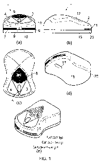
Figure 1 shows a computer mouse incorporating a fuel cell in which figure 1 a
shows a forward end view, figure lb shows a left side view, figure 1 c shows a
plan view,
figure Id shows a lower side perspective view and figure le shows an upper
side
perspective view;
Figure 2 shows a fuel cartridge used in the mouse of figure 1, in which figure
2a
shows a forward end view, figure 2b shows a left side view, figure 2c shows a
plan view
and figure 2d shows an upper side perspective view;
Figure 3 shows a perspective view of the mouse of figure 1 showing the fuel
cartridge in both disconnected and connected configurations;
Figure 4a shows a perspective view of a computer keyboard incorporating a fuel
cell with fuel cartridge attached, and figure 4b shows a perspective view of
the fuel
cartridge detached;
Figure 5 shows a tablet computer support stand from several perspective
viewpoints with an integrated fuel cell and detachable fuel cartridge;
Figure 6 shows a schematic block diagram illustrating functionality of a
computer
device and fuel cell enabled peripheral device; and
Figure 7 shows a docking station / stand with a photovoltaic panel.
In one aspect, the present invention recognises that many users of portable
computer
devices also use such computer devices in combination with one or more
peripheral
devices such as a mouse, a keyboard, a printer, a scanner, a projector, a
docking station
/ stand and the like. These peripheral devices themselves may also be portable
and can
be constructed to have incorporated within them a fuel cell system capable of
powering
not only the peripheral device itself, but also a portable computer device
when
connected to the peripheral device. The expression 'peripheral device' is
intended to
encompass devices that perform a data input and/or output function to the
computer
3
CA 02852616 2014-04-16
WO 2013/057490 PCT/GB2012/052573
device to which they are electronically attached, and which are physically
separate or
separable from the computer device to which they are electronically attached.
Figure 1 shows an exemplary computer mouse 1 in which a fuel cell system is
incorporated. The computer mouse 1 includes an upper housing portion 2 which
encases conventional mechanical and electronic hardware for performing the
conventional mouse functionality of providing an electrical output indicative
of changing
position of the mouse relative to a support surface on which the mouse is to
be used,
e.g. a mouse mat, table top etc. The upper housing portion includes a set of
conventional mouse buttons such as the left and right buttons 3 and 4. The
mouse may
also include a conventional scroll wheel 5, together with any other control
switches,
buttons, or other control surfaces as known in the art.
Incorporated within the upper housing portion 2 is a fuel cell (not visible in
figure 1). The
fuel cell may be of any suitable type capable of providing an electrical power
output at an
appropriate voltage. A typical requirement would be for a 5 V power output of
up to
several amps current, although higher or lower specifications can be
considered. The
upper housing portion 2 also includes a number of ventilation hole arrays 6, 7
and 8 to
provide ventilation to the fuel cell, e.g. an air source to the cathode side
of a fuel cell.
These ventilation hole arrays are preferably positioned on the upper housing
portion 2 in
positions where there is reduced likelihood that they will be occluded by a
user's hand
during normal operation of the mouse. As shown in figure 1, preferred
positions for the
ventilation hole arrays 6, 7, 8 include forward positions indicated by hole
arrays 6 and 7
on a forward surface 10 of the housing close to where the mouse lead would
ordinarily
emerge, indicated by lead aperture 9 in figure 1a. The lead itself is not
shown for clarity
in figure 1 but is seen in figure 3. These forward positions of arrays 6 and 7
are typically
well forward of the ends of the fingers of a user of the mouse. Another
preferred position
is that shown for the ventilation hole array 8 on the forwardly sloping upper
surface 12 of
the mouse, to the rear of the buttons 3, 4. The positioning of the ventilation
hole array 8
is such that the user's palm and fingers tend to arch over the array without
occluding it.
Comfort of the user of a computer mouse is an important consideration in mouse
design
and the profile of the upper housing portion 2 can be configured to any
suitable profile to
optimise the ergonomics. In a preferred configuration, the ventilation hole
arrays 6 and 7
at the forward end of the mouse are configured as the exhaust vents of the
fuel cell while
4
CA 02852616 2014-04-16
WO 2013/057490 PCT/GB2012/052573
the ventilation hole array 8 can be configured as the air inlet for the fuel
cell. In this way,
the warm air stream from the fuel cell during operation can be vectored away
from the
user's hand.
The base 15 of the mouse 1 preferably provides a substantially planar lower
surface 16
which is configured for sliding engagement with the support surface on which
the mouse
is to be used, e.g. mouse mat, table top and the like. The lower surface 16
may have
any suitable profile (preferably, through not necessarily planar, e.g. concave
upwards),
and may be provided with low friction coatings such as Teflon pads (not shown)
for
optimised sliding motion. The base 15 also serves as a removable fuel
cartridge 20 to
supply the fuel cell with any suitable fluid fuel. The fuel may be stored in
the cartridge in
solid, liquid or gaseous form but is preferably delivered to the fuel cell in
fluid form, e.g.
gaseous or liquid form. Exemplary fluid fuels include hydrogen.
The fuel cartridge 20 is preferably configured to be integrated into the
overall profile of
the mouse housing, though preferably detachable to enable easy fuel
replenishment and
cartridge refilling. In the arrangement shown in figure 1, because the fuel
cartridge 20
defines the base 15 of the mouse, an aperture 17 is formed through the
cartridge 20 to
enable a conventional optical position tracker system to interact with the
support surface
(e.g. mouse mat) on which the mouse is disposed, in accordance with known
designs of
optical mice. The aperture 17 may be configured as a physical aperture right
through
the cartridge 20, such that the fuel containment volume of the cartridge may
be
considered as somewhat toroidal, e.g. 'ring' or 'doughnut' shaped.
Alternatively, the
aperture may be an optical aperture such as a window through the cartridge 20.
The
aperture 17 may alternatively be configured to receive a mechanical
arrangement such
as a tracking ball for conventional position sensing.
A schematic diagram of the fuel cartridge 20 is shown in figure 2. The
cartridge 20
includes an outer peripheral edge 21 that approximately confirms to the
profile of the
upper housing portion and defines the shape of the mouse. The cartridge 20
includes
an upper surface 22 which includes a gas feed connection 23 and a service port
24.
The upper surface 22 engages with the upper housing portion 2 in any suitable
manner,
such as by push-fit or by a mechanical locking or latching arrangement (not
shown).
The gas feed connection 23 is configured to mate with a suitable valve on the
underside
5
CA 02852616 2014-04-16
WO 2013/057490 PCT/GB2012/052573
of the upper housing portion 2 for conveying fluid fuel to the fuel cell. The
service port
24 may provide additional functionality, e.g. for refilling / purging /
cleaning cartridges.
Figure 3 shows a perspective view of the fuel cell mouse 1 with the fuel
cartridge
connected (figure 3b) and disconnected (figure 3a). It can be seen that the
detachable
fuel cartridge 20 itself effectively comprises at least a portion of the
external part of the
housing and thereby serves as a functional base of the mouse, e.g. in
providing the low
friction sliding surface and the optical emission portion of the mouse, or
housing at least
part of any tracker ball mechanism. Removal of the fuel cartridge for
replacement or
replenishment may also enable servicing of the internal components of the
mouse, or
cleaning of the low friction surfaces. In a general aspect, a position sensing
means
exemplified by an optical tracker system or a mechanical tracking ball may be
configured
to sense changes in position of the mouse relative to a support surface on
which the
mouse is to be used, and may operate through the aperture in the fuel
cartridge.
Computer mice are typically designed to be of a certain size for optimal use
by the
human hand. As such, they typically have a significant amount of empty space
within
the housing. This makes it particularly advantageous to use some of this space
to
provide an additional power source, since the space is otherwise wasted.
An alternative peripheral device could be a keyboard. Figure 4 shows a
keyboard 40 in
which a fuel cell system is incorporated. The computer keyboard 40 includes an
upper
housing portion 42 which encases conventional mechanical and electronic
hardware for
performing the conventional keyboard functionality. The upper housing portion
42
includes a set of conventional keyboard keys together with any other control
switches,
buttons, or other control surfaces as known in the art.
Incorporated within the upper housing portion 42 is a fuel cell (not visible
in figure 4).
The fuel cell may be of any suitable type as discussed in connection with the
mouse of
figure 1. The upper housing portion 42 also includes a number of ventilation
hole arrays
(not shown) to provide ventilation to the fuel cell, e.g. an air source to the
cathode side of
a fuel cell. These ventilation hole arrays are preferably positioned on the
upper housing
portion 42 in positions where there is reduced likelihood that they will be
occluded by a
user's hand during normal operation of the keyboard.
6
CA 02852616 2014-04-16
WO 2013/057490
PCT/GB2012/052573
The base 41 of the keyboard 40 preferably provides a substantially planar
lower surface
for providing a stable keyboard support and may include feet or adjustable
legs for
varying the height and/or tilt of the keyboard upper surface. The base 41
serves as a
removable fuel cartridge 45 to supply the fuel cell in the keyboard upper
housing portion
42 with a suitable fluid fuel, as described previously in connection with the
mouse of
figure 1.
The fuel cartridge 45 is preferably configured to be integrated into the
overall profile of
the keyboard housing, though preferably detachable to enable easy fuel
replenishment
and cartridge refilling. The fuel cartridge 45 includes an outer peripheral
edge 43 that
approximately conforms to the profile of the upper housing portion 42 and
defines the
shape of the keyboard. The cartridge 45 includes an upper surface 44 which
includes a
gas feed connection 46 and a service port 47. The upper surface 44 engages
with the
upper housing portion 42 in any suitable manner, such as by push-fit or by a
mechanical
locking arrangement (not shown). The gas feed connection 46 is configured to
mate
with a suitable valve on the underside of the upper housing portion 42 for
conveying fluid
fuel to the fuel cell. The service port 47 may provide additional
functionality, e.g. for
refilling / purging / cleaning cartridges.
Keyboards are typically designed to be of a certain size for optimal use by
human hands.
As such, they typically have a significant amount of empty space within the
housing.
This makes it particularly advantageous to use some of this space to provide
an
additional power source, since the space is otherwise wasted.
Other forms of peripheral device such as scanners, printers, projectors,
docking station /
stands may also be configured to have a fuel cell and cartridge incorporated
therein in
similar manner.
A particular benefit of providing a peripheral device, such as a computer
mouse, with a
fuel cell power source is that the fuel cell can be used not only to power the
peripheral
device itself, but also to power the computer device when connected thereto. A
mouse,
keyboard, printer or the like is conventionally connected to a portable
computer device
by way of a USB, or other similar, electrical connector. The USB or other
connector
conventionally provides a bus for data transfer between the computer device
and the
peripheral and also a power line for transferring power from the computer to
the
7
CA 02852616 2014-04-16
WO 2013/057490
PCT/GB2012/052573
peripheral device to power the peripheral device. In one aspect, the present
invention
recognises that there is considerable advantage in enabling a reverse power
transfer to
take place. In other words, the peripheral device with an on-board fuel cell
can be used
to provide power to the computer device. Thus, the battery life of the
computer device
can be extended by avoiding or reducing power drain on the computer battery
when the
peripheral device is connected thereto. Still further, the peripheral device
could also be
used to recharge the portable computer device when the peripheral is connected
thereto. The peripheral device can be used to recharge the portable computer
device
when it is switched on or off. The peripheral device can be used to power, or
to power
and recharge, the portable computer device when it is switched on.
A preferred arrangement is shown schematically in figure 6. A peripheral
device 60 is
connected to a computer device 65 by way of a USB or similar multifunction
(i.e. power
and data) cable 61. The computer device 65 includes an interface 66 for
connecting
both data and power connectors. These can be combined in a USB type connector,
or
be separate data and power connectors. A similar interface 62 is provided on
the
peripheral device 60. Fuel cell 63 is connected by fuel line 64 to a fuel
cartridge 67. A
data interface 68 provides for data transfer to and/or from the computer
device 65.
Computer peripheral functionality of the peripheral device (e.g. mouse
functionality,
printer functionality, keyboard functionality etc) is provided by circuitry
depicted by the
functional block 69. A power controller 63a may supply power from the fuel
cell 63 to the
interface 62 for supply to the computer device 65 via a power line 61b.
The power transfer from peripheral device 60 to computer device 65 can be
managed
intelligently by using two-way data transfer between the computer device 65
and the
peripheral device 60 on a data line 61a under the control of data interface
68. Thus, the
peripheral device 60 may be configured to indicate, to the computer device 65,
that fuel
cell power is available. In such a circumstance, the computer device 65 may be
configured to detect whether it has mains power or is running on batteries. If
the
computer device has mains power available, it may elect to not demand power
from the
peripheral device, and may supply power to the peripheral device so that the
fuel cell 63
therein may remain inactive or quiescent. If the computer device does not have
mains
power available, it may elect to demand power from the peripheral device, e.g.
sufficient
for full normal operation, or sufficient for assistance to battery operation
(to extend
battery life), or for battery recharge, or combinations thereof.
8
CA 02852616 2014-04-16
WO 2013/057490
PCT/GB2012/052573
The power is preferably delivered from the peripheral device 60 to the
computer device
65 using a common data communication / power lead 61, such as USB or USB-OTG.
However, for backward compatibility with existing hardware or standards, it
may be
preferable to have separate electrical connectors for data (e.g. USB) and
power (e.g. a
conventional or proprietary power plug). Separate electrical connector plugs
may be
provided on the end of a common multicore cable to the peripheral device for
user
convenience. For example, the computer mouse 1 could be provided with a lead
30
(figure 3) which terminates in a junction and split cable pair respectively
terminating in a
USB plug and a power plug.
Data communication between the computer device and the peripheral device could
alternatively be provided by a wireless communication channel such as infrared
or
Bluetooth. Power communication between the peripheral device and the computer
device could alternatively be provided by a wireless technology such as
inductive
transfer of power. This latter aspect could be of particular advantage when
the
peripheral device and the computer device are placed in close proximity to one
another.
In another arrangement shown in figure 5, a docking station I stand 50 for a
tablet
computer 51 is shown. A fuel cell (not shown) is incorporated into the docking
station /
stand. The stand 50 also includes a receptacle 52 for a fuel cartridge 53. The
stand 52
may have a triangular design to provide for at least two different
orientations of use, as
shown respectively where indicated by 54a and 54b. These two orientations can
allow
the stand to serve as a reading and typing plinth. The stand may comprise a
hinged
arrangement for altering the angle of presentation of the tablet computer 51.
The
receptacle 52 for receiving a fuel cartridge 53 may be a recess or hole as
shown in
figure 5 into which the cartridge may be inserted. Alternatively, the fuel
cartridge could
be attached to and form a part of the base of the docking station / stand in a
similar way
to that described in connection with the mouse and keyboard embodiments
described
above.
A docking station / stand is conventionally of a size that is at least partly
determined by
the size of the tablet computer being attached thereto and thus typically has
a significant
amount of empty space within the housing. This makes it particularly
advantageous to
9
CA 02852616 2014-04-16
WO 2013/057490 PCT/GB2012/052573
use some of this space to provide an additional power source, since the space
is
otherwise wasted.
The docking station / stand may be connected to a computer device (tablet) by
way of a
USB or similar multifunction (i.e. power and data) cable as described above.
More
preferably, the cable would be replaced by a set of connectors on the side or
base of the
tablet which automatically connect to complementary connectors on the docking
station /
stand when the tablet is mounted thereto. The close proximity of the tablet
computer
device to the docking station / stand also makes the possibility of wireless
power and
data transfer easier and potentially advantageous. Power transfer between the
tablet
computer and the docking station / stand can be managed intelligently by using
two-way
data transfer as described earlier in connection with the mouse and keyboard
arrangements.
In a further arrangement, as shown in figure 7, the docking station / stand 70
may
include a photovoltaic panel 71 as a supplementary power source for charging a
tablet
computer device 51 thereon. The photovoltaic panel 71 may be configured as a
folding
series of panels 72a, 72b, 72c which can unfold over a tablet computer device
51 when
it is not in use. Charging power can be routed to the tablet 51 via the
docking station /
stand 70, and from there to the tablet 51 using the same power delivery
mechanism as
used for a fuel cell incorporated into the docking station / stand 70. In a
more general
aspect, the docking station / stand 70 may incorporate a number of
photovoltaic cells
disposed on any convenient surface of the docking station / stand 70 which can
be used
as an alternative or additional power source to the fuel cell, either for
standby charging
when a tablet is not in use, or an auxiliary power source when the tablet is
in use. A
switching mechanism (not shown) could be incorporated into the docking station
/ stand
70 which switching mechanism is triggered by folding back the photovoltaic
panels 72 for
use of the tablet computer device 51. The switching mechanism may switch on
the fuel
cell in readiness for powering the tablet computer device 51. The tablet
computer device
51 might also be automatically powered up when the photovoltaic panels 72 are
folded
back. The switching mechanism could be a magnetic switch, a microswitch, a
proximity
switch, optical sensor, for example.
All of the embodiments described above of a significant advantage that the
battery life of
a portable computer device can be extended without necessarily increasing
battery size
CA 02852616 2014-04-16
WO 2013/057490
PCT/GB2012/052573
and / or performance by the expedient location of a fuel cell power system in
a
peripheral device such as a mouse or docking station I stand that may be
commonly
also used by the person carrying the portable device. Such a peripheral may,
without
any action required of the user, intelligently supplement the power available
to the
portable device to provide full or partial operating power and / or recharging
power.
Other embodiments are intentionally within the scope of the accompanying
claims.
11