Note: Descriptions are shown in the official language in which they were submitted.
CA 02853310 2014-04-24
WO 2013/063682
PCT/CA2012/000979
AIR SEEDER MANIFOLD APPARATUS
This invention is in the field of agricultural air seeders and in particular a
manifold
apparatus for dividing and distributing the air stream and agricultural
products entrained
therein.
BACKGROUND
Air seeders are well known for seeding agricultural crops. Air seeders
typically comprise
a frame with furrow openers mounted thereon that are configured to create
furrows in a
field surface. Air seeders include one or more tanks containing agricultural
products such
as seeds, chemicals, and fertilizers. Metering devices dispense agricultural
products from
each tank into a distribution network connected between the tanks and the
furrow
openers, and a fan creates an air stream flowing through the distribution
network to carry
the agricultural products from the tanks to the furrow openers. The
distribution network
commonly includes one or more larger primary conduits from the tanks to the
frame,
which are connected to the input port of a manifold which receives the air
stream and
divide and direct the air stream, and the agricultural products entrained in
the air stream,
through output ports into a number of smaller secondary conduits. The
secondary
conduits carry the air stream and products downstream to another manifold for
further
division, or to the furrow openers.
The air flow through the distribution network must be sufficient to maintain
the
agricultural products in the air stream. When the air stream is too slow, the
product drops
out of the air flow and plugs the conduit. As farmers farm larger tracts of
land, air
seeders have become wider, and the conduit network longer, and plugging
becomes more
problematic. Longer conduits require a higher velocity air stream in order to
ensure the
products are maintained in the air stream.
1
SUBSTITUTE SHEET (RULE 26)
CA 02853310 2014-04-24
WO 2013/063682
PCT/CA2012/000979
Higher product and air velocities can damage the seeds as a result of
collision with other
seeds or hard surfaces. Seeds traveling at high speed out of the output end of
a conduit at
the furrow opener often hit the bottom of the furrow and then bounce up,
landing in the
looser soil above the bottom of the furrow, or even bouncing completely out of
the
furrow. Equipment and power requirements are also greater where more and
faster air is
required. Reducing the resistance to air flow through out the distribution
network is
therefore desirable.
In order to achieve substantially equal division of the agricultural products
entrained in
the air stream, it is necessary to have the products randomly distributed
across the cross-
section of the primary conduit as it enters the manifold input port. The air
stream
entering the manifold moves substantially equally out of the manifold through
each
output port, and an imbalance in the amount of product in one part of the air
stream
compared to another will result in a similar imbalance in the quantity of
agricultural
products carried out through one output port compared to another.
In a typical configuration, the manifold is a short cylindrical shape and is
mounted on top
of a vertical tower section of the primary conduit. The input port is at the
center of the
bottom plate of the manifold, and the output ports are equally spaced around
the
cylindrical wall of the manifold between the top and bottom plates. The number
of
output ports will vary with the particular application.
The vertical tower section helps to move the suspended product into a more
even or
centered distribution across the cross section of the tower portion of the
primary conduit.
The bottom end of the tower section is connected through a curved elbow to a
horizontal
section of the primary conduit. In the horizontal section the agricultural
products tend to
move toward the bottom side of the conduit in response to gravity, and the
vertical tower
section is designed to take out the effects of gravity. As the air flow moves
around the
curve elbow at the bottom of the manifold system the product tends toward the
outside of
2
SUBSTITUTE SHEET (RULE 26)
CA 02853310 2014-04-24
WO 2013/063682
PCT/CA2012/000979
the curve giving an offset distribution of product, and various means are then
used to shift
the product to a random or centered distribution.
For example, United States Patent Number 4,575,284 to Kelm provides
projections or
dimples extending inward from the wall of the vertical tower section to help
the granular
material reach the manifold input port in a centered, accurate stream.
Canadian Patent
Number 2,111,611 to Bourgault discloses a seed centering system comprising one
or
more tapered centering rings which direct the agricultural products away from
the walls
toward the center of the horizontal and vertical tower sections of the primary
conduit. A
divider in the elbow also reduces the movement of product toward the outside
of the
elbow.
United States Patent Number 6,290,433 to Poncelet discloses a manifold where
the input
port gradually tapers inwardly in the direction of the flow to accelerate and
centre the
flow as it enters the manifold. Poncelet also discloses a manifold top plate
or cap with a
downward extending point centered on the central axis of the input port. A
series of
smoothly curved grooves and ridges extending from the point upward and curving
90
degrees to connect the grooves with the output ports. Corresponding grooves
and ridges
are provided in the bottom plate and the ridges in the top and bottom plates
cooperate to
essentially form substantially separate channels from an open area just above
the input
port near the point to each output port.
Similarly, Canadian Patent Application Number 2,073,237 of Memory discloses a
divider
header or manifold for air seeders where the vertically oriented input port
tapers inwardly
in the upward direction of air stream flow to centre the flow as it enters the
manifold.
The upward flowing air stream contacts a downward extending point centered on
the
central axis of the input port, and then flows into individual output channels
which extend
upward at an angle and then curve downward to out ends that are adapted to be
connected
to secondary conduits.
3
SUBSTITUTE SHEET (RULE 26)
CA 02853310 2014-04-24
WO 2013/063682
PCT/CA2012/000979
The Poncelet and Memory devices are directed to providing a smooth flow of
product
from the input to the output ports in order to reduce flow resistance, as well
as providing
equal distribution of the agricultural products in the air stream.
SUMMARY OF THE INVENTION
It is an object of the present invention to provide an air stream distributing
manifold
apparatus for an air seeder that overcomes problems in the prior art.
In a first embodiment the present invention provides a manifold apparatus for
an air
seeder. The apparatus comprises a top wall, a bottom wall, and a side wall
enclosing a
manifold interior. A plurality of output ports is defined in a lower portion
of the side
wall, and spaced around the sidewall, each output port adapted for connection
to a
secondary conduit. An input port is defined in the bottom wall, and a
substantially
vertically oriented input conduit extends upward through the input port into
an upper
portion of the manifold interior. A plurality of substantially vertical
channels each extend
downward from an inner top wall surface to one of the outlet ports and has an
entrance
opening at a top end thereof. The upper portion of the manifold interior is
configured
such that an air stream carry entrained agricultural products passing out an
open top end
of the input conduit contacts the top wall and is directed outward into the
entrance
openings, and such that a substantially equal portion of the air stream and
agricultural
products flows into each entrance opening.
In a second embodiment the present invention provides a substantially vertical
input
conduit for an air seeder manifold. A bottom end of the input conduit is
connected
through an elbow to a horizontal conduit, and a top end of the input conduit
is connected
to an input port of the manifold. The input conduit comprises at least one
pulsating ring
located inside the input conduit between the elbow and the top end thereof,
and a bottom
4
SUBSTITUTE SHEET (RULE 26)
CA 02853310 2014-04-24
WO 2013/063682
PCT/CA2012/000979
edge of the at least one pulsating ring extends inward substantially
perpendicularly from
an inner surface of the input conduit.
In response to impact with dimples in the vertical input conduit, or in one
aspect of the
invention impact with blunt bottom edges of pulsating rings disposed in the
input conduit,
the particles of agricultural products entrained in the air stream spin and
bounce against
each other such that the particles have kinetic energy not only from their
forward motion
in the direction of the air stream along the input conduit, but also random
kinetic energy
from spinning and moving laterally randomly across the input conduit. In the
present
invention the particles are not centered in the air stream when same enters
the input port
of the manifold, but rather are randomly and equally distributed across the
cross-section
of the input conduit so that any selected portion of the air stream contains
about the same
quantity of particles as any other selected portion of the same size. Thus
when the center
of the air stream contacts the pointed end of the divider cone, the air stream
flows equally
up all around the slope of the cone and equally into each channel, and an
equal amount of
product is carried into each channel.
Advantageously the cross-sectional area of at least a middle portion of each
channel is
greater than the cross-sectional area of the secondary conduits, and is also
greater than
the cross-sectional area of the channel entrance opening. As the air stream
passes
through the entrance openings into the channels, the speed of the air stream
drops
somewhat and the particles are also accelerated by gravity which reorients and
reduces
the random kinetic energy of the particles, and the incidence of plugging is
reduced.
DESCRIPTION OF THE DRAWINGS
While the invention is claimed in the concluding portions hereof, preferred
embodiments
are provided in the accompanying detailed description which may be best
understood in
5
SUBSTITUTE SHEET (RULE 26)
CA 02853310 2014-04-24
WO 2013/063682
PCT/CA2012/000979
conjunction with the accompanying diagrams where like parts in each of the
several
diagrams are labeled with like numbers, and where:
Fig. 1 is a cut-away side view of an embodiment of a manifold apparatus of the
present
invention for an air seeder;
Fig. 2 is a cut-away side view of the embodiment of Fig. 1 with the cap
removed;
Fig. 3 is a perspective exterior view of the embodiment of Fig. 1 with the cap
removed;
Fig. 4 is a perspective exterior view of the embodiment of Fig. 1 with the cap
installed;
Fig. 5 is a perspective view of an annular channel insert member that is
inserted in the
manifold interior between the sidewall and the input conduit to provide the
channels;
Fig. 6 is a schematic illustration of the relative areas of a channel and a
secondary
conduit;
Fig. 7 is a perspective view of another embodiment of a manifold apparatus of
the
present invention for an air seeder;
Fig. 8 is a perspective view of the cap of the embodiment of Fig. 7;
Fig. 9 is a schematic side sectional view of a further alternate embodiment of
a
manifold apparatus of the present invention for an air seeder.
6
SUBSTITUTE SHEET (RULE 26)
CA 02853310 2014-04-24
WO 2013/063682
PCT/CA2012/000979
DETAILED DESCRIPTION OF THE ILLUSTRATED EMBODIMENTS
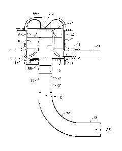
Figs. 1 ¨ 4 illustrate an embodiment of a manifold apparatus 1 of the present
invention
for use on an air seeder. The apparatus 1 comprises a top wall 3, a bottom
wall 5, and a
sidewall 7 enclosing a manifold interior 9.
A plurality of output ports 11 are defined in a lower portion of the sidewall
7, and are
equally spaced around the cylindrical sidewall 7. Each output port 11 is
adapted for
connection to a secondary conduit 13. In the illustrated apparatus 1, a hose
adapter 15 is
attached over each output port 11 and is configured such that an inner surface
17 of the
secondary conduit 13 is aligned with the opening of the output port 11 such
that the air
stream and entrained agricultural products will flow smoothly out the port 11
and into the
secondary conduit 13.
An input port 19 is defined in the bottom wall 5, and a substantially
vertically oriented
input conduit 21 extends upward through the input port 19 into an upper
portion of the
manifold interior 9.
A plurality of substantially vertical channels 31 each extends downward from
the inner
top wall surface 29 to one of the output ports 11, and has an entrance opening
47 at a top
end thereof adjacent to the inner top wall surface 29. The channels 31 are
defined by
divider plates 39 that extend down from the inner top wall surface 29 between
the
sidewall 7 and the input conduit 21. To facilitate a smooth flow of air and
product and
reduce resistance to flow a smoothly curved transition surface 33 at a bottom
end of the
channel 31 connects the vertical channel 31 to the output port 11.
The upper portion of the manifold interior 9 is configured such that an air
stream AS
carrying entrained agricultural products passing out the open top end 27 of
the input
conduit 21 contacts the top wall 3 and is directed outward into the entrance
openings 47,
7
SUBSTITUTE SHEET (RULE 26)
CA 02853310 2014-04-24
WO 2013/063682
PCT/CA2012/000979
and such that a substantially equal portion of the air stream and entrained
agricultural
products flows into each entrance opening 47.
In a conventional manifold with a generally flat top wall, generally of a soft
material to
reduce seed damage, the air stream with entrained agricultural products blows
up against
the bottom surface and then laterally out the outlet ports. It is contemplated
that such a
flat top wall could be used to similarly direct the air stream and products
into the entrance
apertures 47 of the vertical channels 31 with satisfactory results however to
improve flow
and equality of division, in the illustrated apparatus 1, a divider cone 23
extends, with
pointed end 25 down, from the top wall 3 above the open top end 27 of the
input conduit
21 such that the axis AA of the cone is aligned with the longitudinal axis BB
of the input
conduit 21. Thus the center of air stream AS passing upward out the open top
end 27 of
the input conduit 21 contacts the pointed end 25 of the cone 23 and the air
stream AS and
the agricultural products entrained therein flows up the walls of the cone 23,
and is
substantially equally distributed along the surface of the cone 23. Again to
facilitate
smooth flow in the illustrated apparatus 1 the upper edge of the cone 23
transitions
smoothly into the inner top wall surface 29 that curves outward and then
downward into
the sidewall.
In the apparatus 1, the sidewall 7 is substantially cylindrical, and the top
wall 3 and
divider cone 23 are conveniently incorporated into a cap 35 that is releasably
attached
and sealed to the sidewall 7 by bolts through corresponding holes in the tabs
37 on the
cap 35 and sidewall 7. The cap 35 is shown removed in Figs. 2 and 3.
The channels 31 are defined by divider plates 39 that extend above the
sidewall 7 into
the cap 35 and have rounded top edges 41 that substantially correspond to the
inner top
wall surface 29, such that when the cap 35 is installed, as illustrated in
Fig. 1, the rounded
top edges 41 are in close proximity to the inner top wall surface 29. For
convenience of
8
SUBSTITUTE SHEET (RULE 26)
CA 02853310 2014-04-24
WO 2013/063682
PCT/CA2012/000979
production, the same cap 35 can thus be used regardless of the number of
output ports 11
and corresponding channels 31.
Upper portions 43 of the divider plates 39 extend substantially vertically
above the open
top end 27 of the input conduit 21. Inner edges 45 of the upper portions 43 of
the divider
plates 39 are beveled or sharpened and define a channel entrance opening 47,
as best seen
in Fig. 5, when the cap 35 is installed and the rounded top edges 41 are in
close proximity
to the inner top wall surface 29 of the cap 35. Thus the channel entrance
opening 47 into
each channel 31 is substantially vertical extending downward from about the
upper edge
of the cone 23 where the walls of the cone 23 transition into the inner top
wall surface 29.
Each channel entrance opening 47 is formed on each side by a beveled inner
edge 45
such that agricultural products in the air stream AS flow smoothly into one
entrance
opening 47 or the adjacent entrance opening with reduced impact on the upper
portions
43 of the divider plates 39 forming the opening 47.
Thus the center of air stream AS passing upward out the open top end 27 of the
input
conduit 21 contacts the pointed end 25 of the cone 23 and the air stream AS
and the
agricultural products entrained therein flows up the walls of the cone, and
substantially
equally through each entrance opening 47.
Conveniently the divider plates 39 are incorporated into an annular channel
insert
member 49 that is inserted in the manifold interior 9 between the sidewall 7
and the input
conduit 21. The channel insert member 49 includes a cylindrical inner wall 51
that slides
down and fits tightly around the top end of the input conduit 21.
The bottom end of the input conduit 21 is connected through an elbow 53 to a
horizontal
conduit 55 carrying the air stream AS from the air seeder product tanks. A
number of
pulsating rings 57 are located inside the input conduit 21 between the elbow
53 and the
open top end 27 thereof. Although the number may vary, the illustrated
apparatus 1
9
SUBSTITUTE SHEET (RULE 26)
CA 02853310 2014-04-24
WO 2013/063682
PCT/CA2012/000979
shows two of these pulsating rings 57 installed in the input conduit 21. The
bottom edge
59 of each pulsating ring 57 extends inward substantially perpendicularly from
the inner
surface of the input conduit 21. The bottom edge 59 forms a blunt obstacle to
the air
stream AS and to agricultural products moving with the air stream AS along the
inner
surface of the input conduit 21, and disrupts the flow of product particles
and air.
The upper edge 61 of the illustrated pulsating rings slopes from an inner
surface thereof
toward the inner surface of the input conduit 21.
The upper edge may also be
perpendicular to the inner surface of the input conduit 21 the same as the
bottom edge 59.
The pulsating rings 57 are generally made of a somewhat soft resilient
material, such as
plastic, rubber or the like to reduce damage to seeds contacting the blunt
bottom edges at
high speed. Product particles contacting the bottom edges 59 of the rings 57
bounce
around and impact other particles in the air stream, and generally create a
chaotic flow
with particles spinning and moving in random directions within the air stream
flow.
The vertical input conduit 21 and pulsating rings 57 move the suspended
particles of
agricultural product into a random distribution through-out the cross section
of the input
conduit 21. In the horizontal conduit 55 the agricultural products tend to
move toward
the bottom side of the conduit in response to gravity, and the vertical input
conduit 21 is
designed to take out the effects of gravity. When the air flow switches from
horizontal to
vertical at the bottom of the input conduit 21, the product moving around the
curved
elbow 53 tends to the outside of the curve. Once the product reaches the
vertical input
conduit 21 it tends to rhythmically bounce from one side of the conduit to the
other in an
"S" pattern as it moves up. This rhythmic pattern changes with air speed,
product speed,
product density, product shape, product surface texture, and product quantity.
To achieve a more random product distribution within the conduit cross-section
(without
introducing extremely tall towers), a common practice is to use shorter towers
and to
SUBSTITUTE SHEET (RULE 26)
CA 02853310 2014-04-24
WO 2013/063682
PCT/CA2012/000979
introduce dimpling within the vertical input conduit 21. The dimples are
formed by
denting in a localized point of the wall of the input conduit 21. The dimples
create a
product flow chaos situation in the vertical input conduit 21 as the particles
bounce off
the dimples and helps reduce the rhythmic pattern of product flow. To overcome
the
rhythmic patterns manufacturers have introduced an increased number of dimples
and
have made the dimples more aggressive, which results in increased resistance
to high
product flows and plugging. The pulsating rings 57 of the present invention
provide
reduced resistance to air flow compared to an excessive number of dimples.
Prior art input conduits such as the tapering centering rings of Bourgault
described above,
try to direct entrained agricultural products toward the center of the air
stream AS.
In the illustrated apparatus 1 of the present invention the inner diameter ID
of the input
conduit is substantially the same from the elbow 53 to the open top end 27 of
the input
conduit 21, except where the pulsating rings 57 reduce the effective inner
diameter for a
short distance. Entrained particles of agricultural products that impact the
pulsating rings
57 cause the entrained particles of agricultural products to move in a more
random
manner with a view to distributing the entrained products equally across the
cross-section
of the input conduit 21, so that when the air stream AS contacts the pointed
end 25 of the
cone 23 and the air stream AS is substantially equally distributed into each
channel
entrance opening 47, each channel 31 receives a substantially equal proportion
of the
entrained agricultural products as well as an equal proportion of the air
stream AS.
By centering the particles of agricultural products in the air stream AS as in
the prior art
of at least Bourgault, a small deviation of the center of the stream of
agricultural product
particles from the center of the top plate shown in Bourgault will result in
an increased
variation in product distribution compared to where the product is evenly
distributed
across the entire cross-section of the input conduit as in the present
invention.
11
SUBSTITUTE SHEET (RULE 26)
CA 02853310 2014-04-24
WO 2013/063682
PCT/CA2012/000979
The impact of the product particles on the bottom edge 59 of the pulsating
rings 57
causes the particles to spin and bounce against each other such that the
particles have
kinetic energy not only from their forward motion in the direction of the air
stream AS
along the input conduit 21, but also random kinetic energy from spinning and
moving
laterally randomly across the input conduit 21.
As seen in Figs. 5 and 6, the cross-sectional area Al of at least a middle
portion of each
channel 31 is greater than the cross-sectional area A2 of the secondary
conduits 13. The
cross-sectional area Al is also greater than the cross-sectional area A3 of
the entrance
opening 47. Thus as the air stream passes through the entrance openings 47
into the
channels 31, the speed of the air stream drops somewhat as the volume of the
passage the
air stream is passing through expands and the particles begin to move downward
in the
channels 31. The particles are also accelerated by gravity in the channel 31
and this
combination of reduced speed and gravity at least somewhat reorients the
particles and
reduces the random kinetic energy thereof such that the particles are more
readily carried
in a smooth flow in the air stream along the smoothly curved transition
surface 33 at the
bottom end of the channels 31, and into the secondary conduits 13, and the
incidence of
plugging is reduced.
Figs. 7 and 8 illustrate another embodiment of a manifold apparatus 101 of the
present
invention for use on an air seeder where the channels 131 are defined by
divider plates
139 extending between the sidewall 107 and the input conduit 121, and wherein
upper
portions 143 of the divider plates 139 extend above the open top end 127 of
the input
conduit 121 and curve to join the inner top wall surface 129 and an upper
portion of a
wall of the cone 123 such that inner edges 145 of the upper portions 143 of
the divider
plates 139 define curved entrance openings 147.
12
SUBSTITUTE SHEET (RULE 26)
CA 02853310 2014-04-24
WO 2013/063682
PCT/CA2012/000979
In the apparatus 101, the agricultural product particles will flow up the
sloped wall of the
cone 123. Upper ends 165 of the inner edges 145 of the upper portions 143 of
the divider
plates 139 adjacent to the cone 123 are therefore beveled to reduce impact
damage.
As in the apparatus 1 described above, in apparatus 101 the sidewall is
substantially
cylindrical, and the top wall 103, divider cone 123, and curved upper portions
143 of the
divider plates 139 are incorporated into a cap 135 that is releasably
attachable to the
sidewall 107. When the cap 135 is attached to the sidewall 107, the upper
portions 143
of the divider plates 139 are aligned with lower portions 163 of the divider
plates 139 that
are located between the sidewall 107 and the input conduit 121. In the
apparatus 101 the
cap 135 must be selected to correspond to the number of channels 131 and
output ports
with hose adapters 115.
Fig. 9 schematically illustrates a further embodiment of a manifold apparatus
201 of the
present invention for use on an air seeder. Again a smoothly curved transition
surface
233 at a bottom end of an inner side of each vertical channel 231 connects the
vertical
channel to the output port 211. An upper edge of the cone 223 transitions
smoothly into
the inner top wall surface 229 as in the embodiments described above, however
in the
apparatus 201 the inner top wall surface 229 on the right side of the drawing
curves
outward farther and then curves downward and back inward to the top edge of
the
sidewall 207, and in the illustrated embodiment somewhat past the inner
surface of the
sidewall 207, such that the surface 229' is oriented at an angle N' with
respect to the
sidewall 207, instead of being aligned vertical with the sidewall as in the
embodiments
above, and as illustrated in the inner top wall surface 229 on the left side
of the drawing.
Thus in the apparatus 201 the agricultural products, indicated by the arrows,
entrained in
the air stream AS and moving along the right inner top wall surface 229' are
directed
from an upper outer portion 231A of the vertical channel 231 downward and
across the
channel to an upper portion of the curved transition surface 233. The
agricultural
1,3
SUBSTITUTE SHEET (RULE 26)
CA 02853310 2014-04-24
WO 2013/063682
PCT/CA2012/000979
products contact the transition surface 233 at a relatively low angle N and
follow the
curved transition surface 233 to be redirected more smoothly to a horizontal
flow
direction out through the output port 211.
In contrast the agricultural products entrained in the air stream AS and
moving along the
left inner top wall surface 229 are directed from an upper outer portion 231A
of the
vertical channel 231 downward along the sidewall 207 and into contact with the
bottom
portion of the curved transition surface 233 where the surface 233 is almost
horizontal
and the impact angle N is much higher, and the speed of the air stream AS and
products
is more slowed and disrupted compared to the air stream AS.
The foregoing is considered as illustrative only of the principles of the
invention.
Further, since numerous changes and modifications will readily occur to those
skilled in
the art, it is not desired to limit the invention to the exact construction
and operation
shown and described, and accordingly, all such suitable changes or
modifications in
structure or operation which may be resorted to are intended to fall within
the scope of
the claimed invention.
14
SUBSTITUTE SHEET (RULE 26)