Note: Descriptions are shown in the official language in which they were submitted.
CA 02853372 2014-06-04
Attorney Docket: 3194-4/5
WIRELESS LIGHT SWITCH SYSTEM AND METHOD,
LOAD CONTROLLER DEVICE, AND REMOTE SWITCH DEVICE
Technical Field
10001] The present disclosure relates to wireless control of electrical
fixtures within a
building structure, and in particular to a wireless light switch system for
controlling light
fixtures.
Technical Background
100021 In both residential and commercial buildings, wireless control of
electrical
fixtures and appliances, such as light fixtures, has gained popularity due to
its advantages
over hardwired control of fixtures and appliances. For example, wireless light
switch
systems that employ a wireless control device that sends radiofrequency (RF)
commands
to a receiver controlling a light fixture do not necessarily require that both
the wireless
control and the corresponding load be connected to the same circuit, unlike a
traditional
wired light switch and load. This relaxes some constraints on the relative
positioning of
the switch and the load. Some wireless solutions permit light fixtures to be
controlled by
a handheld remote control device, avoiding the need to mount the wireless
control device
on a wall. Regardless, there is still a general desire to provide fixed-
position (e.g., wall-
mounted) wireless controls similar in appearance and effect to commonly
available
switches used with wired fixtures.
[0003] There are currently available on the market wall-mounted wireless light
switch
transmitter devices that have the appearance of commonly available switches
and switch
plates, or that can be used with current models of switch plates. Some devices
of this type
use an external power source and therefore require wiring and mounting on an
electrical
box. In the case where a building with hardwired switches is to be retrofitted
with
wireless switches, the positioning of wall-mounted wireless switches is again
constrained
by the locations of existing electrical boxes, unless the installer is willing
or able to install
1
CA 02853372 2014-06-04
and wire new electrical boxes. Other devices of this type employ an internal
power
supply and may not require wiring; however, the dimensions of the power source
and
associated circuitry still require special accommodation, for instance by
mounting the
device on an electrical box with space to accommodate these components, or by
providing a specially-designed switch plate and enclosure that differs in size
or
appearance from commonly available switch plates. Specially-designed switch
plates, in
particular, may jut out further from the wall and/or have a noticeably thicker
appearance.
[0004] Similar concerns can also arise concerning the placement of the
wireless receiver
units that are used in conjunction with wireless light switch transmitter
devices to control
power flow to a light fixture. The wireless receivers must be positioned to
receive a
signal from the transmitter or from a central controller, and their size may
prohibit them
from being mounted in a discrete location.
Brief Description of the Drawings
[0005] The accompanying drawings illustrate, by way of example only,
embodiments of
the present disclosure. In the accompanying drawings, like reference numerals
describe
similar items throughout the various figures.
[0006] FIG. 1 is a schematic of an example network topology for a wireless
light switch
system operating over a home area network.
100071 FIG. 2 is a schematic of an example of a remote switch device for use
in the
wireless light switch system of FIG. 1.
[0008] FIG. 3 is a schematic of an example of a load controller for use in the
wireless
light switch system of FIG. 1.
[0009] FIG. 4 is a schematic of an example of a network key device for use
with the
wireless light switch system of FIG. 1.
[0010] FIG. 5 is a flowchart of an example overview method for use with the
wireless
light switch system of FIG. 1.
2
CA 02853372 2014-06-04
[0011] FIG. 6 is a flowchart of an example control flow for the remote switch
device of
FIG. 2.
[0012] FIG. 7 is a flowchart of an example control flow for the load
controller of FIG. 3.
[0013] FIG. 8 is a flowchart and accompanying communication diagram for
initialization
of a device in the wireless light switch system of FIG. 1.
[0014] FIG. 9 is a state diagram of the load controller during an association
procedure.
[0015] FIG. 10 is a flowchart and accompanying communication diagram for a
load
controller receiving and executing a command from another device in the
wireless light
switch system of FIG. 1.
[0016] FIG 11 is a flowchart illustrating a method for storing incremented
values in
memory.
[0017] FIGS. 12 and 13 are front and back elevations, respectively, of an
assembled
remote switch device.
[0018] FIGS. 14 and 15 are front and back perspective views, respectively, of
the remote
switch device of FIGS. 12 and 13 as they would be mounted in a standard switch
cover
plate.
[0019] FIG. 16 is an exploded perspective view of the remote switch device of
FIGS. 12
and 13.
[0020] FIG. 17 is a rear perspective view of a rocker switch shell of the
remote switch
device of FIG. 16.
[0021] FIGS. 18A and 18B are front and back perspective views, respectively,
of an
actuator component of the remote switch device as shown in FIG. 16.
[0022] FIG. 18C is a cross-sectional view of the actuator component of FIG.
18A taken
along line A-A.
3
CA 02853372 2014-06-04
[0023] FIG. 19 is a schematic illustrating positioning of select circuit
components of the
remote switch device of FIG. 2 on a printed circuit board.
[0024] FIG. 20 is a front perspective view of an assembled load controller.
[0025] FIGS. 21 and 22 are top plan and side elevation views of the load
controller of
FIG. 20 as it may be positioned in a standard-sized octagon electrical box.
[0026] FIG. 23 is a rear perspective exploded view of the load controller of
FIG. 20.
Detailed Description of the Invention
[0027] There is accordingly provided a wireless load control system,
comprising: one or
more wireless switch components, each wireless switch component including a
surface-
mountable assembly comprising a mechanical user control interface, a wireless
transmitter, and a microprocessor in communication with the wireless
transmitter, the
microprocessor being configured to, in response to a signal triggered by
actuation of the
user control interface, send a control signal to at least one load controller
component; a
plurality of load controller components, each load controller component being
adapted
for mounting in a junction box associated with one or more loads, each load
controller
component including an enclosure adapted to fit within the junction box, a
wireless
transceiver adapted to receive control signals from wireless switch components
and
transmit messages to other load controller components, and a control circuit
comprised in
the enclosure configured to control current delivered to the one or more loads
in response
to received control signals, the plurality of load controller components being
configured
to communicate with each other over a mesh network while the one or more
wireless
switch components arc configured to send control signals without participating
in the
mesh network, each of the plurality of load controller components being
adaptable to be
paired with at least one of the one or more wireless switch components, and
two or more
of the plurality of load controller components being adaptable to be paired
with a same
wireless switch component at the same time.
4
CA 02853372 2014-06-04
[0028] In one aspect of the wireless load control system at least two of the
plurality of
load controller components are adapted to be paired with the same wireless
switch
component.
[0029] In another aspect, at least one of the plurality of load controller
components is
adapted to be paired with at least two of the one or more wireless switch
components.
[0030] In still another aspect, at least two of the plurality of load
controller components
are adapted to be paired with the same wireless switch component.
[0031] One aspect of the invention provided herein is a wireless remote switch
assembly
for use in the wireless system. There is provided an assembly for a wireless
switch,
comprising; a base adapted for mounting on a surface, the base comprising a
back plate
having a first face mountable on the surface and at least one base sidewall
projecting
from an opposing face of the base; a rocker shell comprising at least one
oblique wall
extending between a pivot axis and an end of the rocker shell and at least one
rocker shell
sidewall extending from the at least one oblique wall, the rocker shell being
pivotably
mounted to the base at the pivot axis, the at least one base sidewall and the
at least one
rocker shell sidewall cooperating to define an enclosure; a control circuit
comprised in
the enclosure, the control circuit including at least one switch contact in
electrical
communication with an internal power source interface and a microprocessor
controlling
a wireless transmitter; at least one elastically deformable actuator disposed
in the
enclosure proximate to an end of a corresponding oblique wall of the rocker
shell, the at
least one elastically deformable actuator having a body comprising a contact
member
having a bearing surface at a first end and an opposing second end, the
opposing second
end being provided with a conductive contact, each actuator being positioned
such that
each conductive contact is substantially aligned with a corresponding switch
contact,
each contact member being movable between an engaged position with the
corresponding
switch contact when force is applied to the bearing surface via the
corresponding oblique
wall, and a disengaged position when the force is removed.
CA 02853372 2014-06-04
100321 In one aspect, a depth of the at least one rocker shell sidewall is
greater proximate
to the pivot axis than proximate to the end of the rocker shell.
[0033] In another aspect, the rocker shell comprises a pair of oblique walls
meeting at the
pivot axis.
[0034] In still another aspect, the at least rocker shell sidewall comprises a
substantially
continuous sidewall and the at least one base sidewall comprises a
substantially
continuous sidewall.
[0035] In yet another aspect, the at least one rocker shell sidewall is
adapted to receive
and pivot on corresponding lugs provided on an interior of the at least one
base sidewall.
[0036] In a further aspect, the at least one rocker shell sidewall is sized to
fit within an
interior of the at least one base sidewall, and exterior dimensions of the at
least one base
sidewall are sized to fit within a light switch cover plate.
[0037] In another aspect, a depth of the assembly is up to about 10mm.
[0038] In another aspect, a depth of the enclosure as defined by the base is
up to about
7mm.
[0039] In yet aspect, the first face is substantially flat.
[0040] In another aspect of the assembly, each elastically deformable actuator
further
comprises a collapsible collar projecting from a first face of a actuator base
member, the
second end of the contact member being supported by the collapsible collar,
the
collapsible collar flexing to permit travel of the contact member though the
collapsible
collar and the actuator base member to the engaged position when force is
applied to the
bearing surface, wherein in the engaged position the conductive contact
provided on the
second end is in electrical communication with the corresponding switch
contact.
[0041] In another aspect of the actuator, the bearing surface comprises a
substantially flat
surface. In some examples, the bearing surface is inclined at substantially a
same angle of
6
CA 02853372 2014-06-04
inclination as the corresponding oblique wall. In other examples, the
collapsible collar
and the contact member are substantially polygonal. Still further, the contact
member
may further comprise an alignment recess for aligning the actuator with a
complementary
alignment pin provided on an interior surface of the corresponding oblique
wall. Also, the
contact member, collapsible collar, and actuator base member may be integrally
formed
of silicone.
[0042] In another aspect, the at least one switch contact, internal power
source interface,
microprocessor, wireless transmitter and an antenna in communication with the
wireless
transmitter are provided on a circuit board mounted within the base sidewall,
and the at
least one elastically deformable actuator is disposed between the circuit
board and the
corresponding oblique wall.
[0043] Still further, the at least one switch contact comprises conductive
traces on the
circuit board.
[0044] In another aspect, the assembly comprises a pair of elastically
deformable
actuators, the rocker shell comprising a pair of oblique walls meeting at the
pivot axis,
and the control circuit comprising a pair of switch contacts, each switch
contact being
positioned proximate to an end of the circuit board, wherein the internal
power source
interface is disposed on the circuit board at a position proximate to the
pivot axis between
the pair of switch contacts, and at least one of the wireless transmitter and
the
microprocessor are disposed on the circuit board between the pair of switch
contacts.
[0045] In another aspect, the control circuit further includes a battery power
source
mounted on the internal power source interface.
[0046] Another aspect of the invention provided herein is a load controller
and assembly
for use with a wireless switch controller assembly, the assembly comprising a
load
controller, comprising: an enclosure adapted to fit within a junction box, the
enclosure
comprising a projecting fitting adapted to fit through an aperture of the
junction box to
maintain the enclosure in fixed relation to the junction box, the enclosure
comprising an
7
CA 02853372 2014-06-04
antenna port disposed within the fitting and permitting passage of an antenna
therethrough; and a control circuit comprised in the enclosure, the control
circuit being
configured to control mains current delivered to a load, the control circuit
including a
microprocessor in communication with a wireless transceiver and the antenna,
the
antenna extending from an interior of the enclosure through the antenna port
to an
exterior of the enclosure; such that when the enclosure is mounted in a
junction box such
that the fitting extends through the aperture of the junction box to project
to an exterior of
the junction box, the antenna thus extends to an exterior of the junction box.
[0047] In one aspect of the load controller assembly, antenna comprises a whip
antenna
or a wire antenna.
[0048] In another aspect, the microprocessor is configured to control the
mains current
delivered to the load in response to commands received by the wireless
transceiver.
[0049] In still another aspect, the enclosure comprises a base and a
cooperating lid, the
projecting fitting being provided on an exterior surface of a wall of the
base.
[0050] Still further, the antenna port may comprise an aperture through the
wall of the
base.
[0051] In yet another aspect, the projecting fitting comprises a threaded
nipple.
[0052] The assembly may also include the junction box, which in some
embodiments is
metal. In other embodiments, the assembly may further include a light fixture,
which
comprises the load controlled by the assembly.
[0053] In some implementations of the wireless light switch system, security
may be
provided in the form of a rolling code or other similar monotonically
increasing value
that is stored by one or more devices in the system. Accordingly, to improve
performance
of memory components provided in the system, there is also provided a method
of
managing operation of rewritable memory, comprising: reading in a first value
from the
set of one or more memory locations; on detection of an instruction to store
an
8
CA 02853372 2014-06-04
incremented value: permuting the incremented value by, in combination:
applying an
encoding, in which a value of a least significant bit changes only on every
second
increment, to two least significant bits of the incremented value; and on
overflow of a
least significant byte as a result of the increment, applying a cyclic byte-
wise shift to the
incremented value; and storing the permuted incremented value in the one or
more
memory locations.
[0054] In one aspect of this method, wherein the encoding applied to the least
significant
two bits comprises an encoding of a'l = al and a'0 = al 0 a0, wherein a0 is an
initial
value of the least significant bit, a'0 is an encoded value of the least
significant bit, al is
an initial value of a second-least significant bit, and al is an encoded value
of the
second-least significant bit.
[0055] In another aspect, the set of one or more memory locations comprises a
plurality
of memory locations, and the cyclic byte-wise shift comprises shifting a
memory location
allocated to a byte of the first value to a next byte of the incremented
value.
[0056] There is also provided a method of managing operation of rewritable
memory
used to store a sequence of binary values, the method comprising: defining an
allocation
of each one of a plurality of memory blocks in the rewritable memory to a
corresponding
byte position of a multiple-byte value; storing a first multiple-byte value in
the memory
blocks corresponding to the plurality of memory addresses according to the
allocation;
reading in the first value from the memory blocks; incrementing the first
value to provide
an incremented value; encoding two least significant bits of the incremented
value
according to the encoding of a'l = al and a'0 = al 0 a0, wherein a0 is an
initial value of
the least significant bit, al0 is an encoded value of the least significant
bit, al is an initial
value of a second-least significant bit, and a'l is an encoded value of the
second-least
significant bit; when the incrementing of the first value does not result in
an overflow of a
least significant byte, storing the incremented value in the memory blocks
according to
the allocation; when the incrementing of the first value results in an
overflow of a least
significant byte, altering the allocation by cyclically shifting the
allocation of the plurality
9
CA 02853372 2014-06-04
of memory blocks to the corresponding byte positions, and storing the
incremented value
in the memory blocks according to the allocation as altered.
[0057] In one aspect, storing the incremented value comprises rewriting only
those
memory blocks corresponding to bytes of the incremented value that are
changed.
[0058] The method may further comprise maintaining a mapping of the allocation
of the
plurality of memory blocks to the corresponding byte positions.
[0059] In another aspect, only the least significant bit of the first value is
incremented.
100601 There is also provided a method of managing operation of rewritable
memory
used to store an increment of a stored value, the stored value being
represented by
multiple bytes, the multiple bytes being stored in a defined set of blocks of
the rewritable
memory according to a defined byte order, the method comprising: detecting an
instruction to store an incremented value in place of the stored value;
permuting two least
significant bits of the incremented value according to the encoding of al = al
and al0 =
al 0 a0, wherein a0 is an initial value of the least significant bit, a'0 is
an encoded value
of the least significant bit, al is an initial value of a second-least
significant bit, and a'l is
an encoded value of the second-least significant bit; upon determining that
the
incremented value results in an overflow of a least significant byte as
compared to the
stored value, permuting the byte order according to a cyclic byte-wise shift,
and storing
the incremented value as incremented according to the permuted byte order.
[0061] In these methods, the rewritable memory may comprise EEPROM. Further,
the
method may be implemented in where the first value and the incremented value
comprise
values in a rolling code algorithm.
[0062] There is also provided an electronic device comprising memory and a
processor
configured to implement the foregoing methods and variants.
[0063] The embodiments described and depicted herein provide a wireless light
switch
system comprising one or more remote switch devices and corresponding load
controllers
CA 02853372 2014-06-04
capable of many-to-many association for flexible control of light fixtures
over a home
area network. In one implementation, the remote switch devices are
independently-
powered rocker switch-type devices having a low profile and that are capable
of being
installed on a flat surface using conventional, commercially available rocker-
switch wall
plates such as Leviton Decora brand wall plates. The low profile of the
remote switch
devices permits them to be mounted behind a conventional wall plate without
the need
for an electrical box or cutout to accommodate the remote switch device,
thereby
permitting the installer to place the remote switch device wherever desired.
The
corresponding load controllers are sized so that they can be contained inside
conventional
junction boxes (e.g., octagonal electrical boxes) with their antennas
extending through a
knockout, thereby permitting the load controllers to be substantially
concealed, and even
be mounted inside metal junction boxes that would otherwise interfere with RF
reception.
[0064] Pairing between remote switch devices and load controllers may be
accomplished
in some embodiments without requiring manual operation of the load controller.
Security
may be provided for the home area network using encryption and a rolling
(hopping)
code. To reduce implementation cost of the rolling code, a wear-levelling
technique may
be applied to the memory components of the system.
[0065] In accordance with an embodiment, FIG. 1 illustrates an example network
topology for a wireless light switch system 100 for use in a building, whether
for
residential, commercial, or other use. The wireless light switch system 100
includes one
or more remote switch devices 110a-11On (generally referred to herein as
remote switch
device or devices 110), and one or more corresponding load controllers 120a-
120n
(generally referred to as load controller or load controllers 120), the latter
configurable to
participate in a wireless home area network 150. Each of the remote switch
devices 110
and load controllers 120 comprises transmitters, receivers, and/or
transceivers suitable for
operation with a home area network 150 or for communication with other devices
120,
110 in the system 100, as discussed below.
[0066] Each remote switch device 110 is paired with, and can be operated to
control, one
or more corresponding load controllers 120 over the home area network 150.
Each load
11
CA 02853372 2014-06-04
controller 120 in turn controls one or more lighting devices, represented
schematically as
loads 10a-10n. In this embodiment, each load controller 120 is wired to its
corresponding
load or loads 10a-10n; thus, in the example of FIG. 1, controller 120a is
wired to a single
light fixture 10a comprising a single light source; controller 120b is wired
to a single
light fixture 10b comprising multiple light sources; and controller 120n is
wired to
multiple light fixtures 10n. Furthermore, any load controller 120 may be
paired with one
or more corresponding remote switch devices 110. In FIG. 1, stippled lines
between
illustrate example pairings of remote switch device 110a with multiple load
controllers
120a, 120b, and remote switch device 110b with load controller 120b. The
second load
controller 120b is thus controllable using commands issued from either the
remote switch
device 110a or 110b. The number of devices to which each load controller 120
or remote
switch device 110 can be paired may be subject only to programmed limits
configured for
each of the remote switch devices 110 and load controllers 120. As discussed
in further
detail below, the pairing can be an effectively "one way" pairing, where each
load
controller 120 is configured to whitelist one or more select remote switch
devices 110
and thereafter respond only to command signals broadcast by those whitelisted
remote
switch devices 110. In other embodiments, load controllers 120 and remote
switch
devices 110 are mutually paired, with each device 110, 120 storing pairing
information
for its paired devices 120, 110 so that remote switch devices 110 can address
command
signals to specific load controllers 120.
[0067] While each load controller 120 may be capable of receiving control
signals
directly from their paired remote switch device(s) 110, in some cases the load
controllers
120 may be configured as nodes in a home area network 150 to potentially
extend the
reach of a transmitter in a given remote switch device 110 and/or improve
reliability of
the system 100 in the event a direct transmission route between a remote
switch device
110 and a paired load controller 120 is not possible. The home area network
150 is a
wireless network operating using any frequency and protocol suitable for
communication
and control of appliances in a building automation context. In this particular
example, the
network 150 operates over a sub-1GHz band (e.g., 315 or 915 MHz) in compliance
with
applicable regulations. In one embodiment, transmissions between the remote
switch
12
CA 02853372 2014-06-04
devices 110 and the load controllers 120 take place over a 915 MHz band, which
in some
current environments may be preferred over other bands (e.g., 2.4 GHz) due to
lower
likelihood of signal collision and greater signal penetration in a typical
furnished building
structure. However, those skilled in the art will appreciated that a most
suitable wireless
communication standard for use with the wireless light switch system 100 is
one that
provides sufficiently reliable data delivery at an acceptable cost in
resources and power
consumption.
[0068] The home area network 150 may operate in a mesh or star configuration.
In FIG.
1, dashed lines indicate example transmission routes between load controllers
120 and the
optional hub 130, discussed below, in a mesh network. In some cases, for
instance, the
network 150 may operate in compliance with the ZigBee 1.0 or later
specification, or
alternatively in compliance with the Z-Wave wireless communications protocol.
In
other cases a different topology or standard may be selected. In this
disclosure the term
"home area network" is merely intended to distinguish from other local
wireless
networks, such as personal area networks and the like; it will be appreciated
by those
skilled in the art that the term is not intended to restrict the embodiments
described herein
to residential applications.
[0069] The wireless light switch system 100 can include an optional hub device
130 that
operates as a gateway between the home area network 150 and the Internet or
other
suitable public or private network 50 to permit communication with components
of the
system 100 with remote devices (not shown). Remote devices can include servers
or
other communication equipment provided by a utility (e.g., an electricity
distribution
company), or user communication devices, such as a personal computer, laptop,
tablet,
smartphone, or similar device. In the former case, the hub 130 may be
configured as a
smart energy portal that collects utility usage data from connected smart
devices on the
wireless light switch system 100, which could include load controllers 120,
then transmits
this usage data to the utility, or manages the operation of devices on the
home area
network 150. In the latter case, the hub 130 may be configured to collect
status
information from load controllers 120 and transmit the status information to
the user
13
CA 02853372 2014-06-04
communication device, and to receive operation commands (e.g., ON/OFF) from
the user
communication device for forwarding to one or more load controllers 120. The
hub
device 130 may be a distinct computing device dedicated to the wireless light
switch
system 100, or it can be integrated in another appliance or fixture.
[0070] It can be seen in FIG. 1 that the remote switch devices 110 need not
necessarily
operate as nodes in the home area network 150. Rather, they operate
independently of the
network, and simply broadcast messages to any receiving devices within range.
In such
an embodiment, the remote switch devices 110 do not need to be equipped with
RF
receivers or transceivers, but merely require an RF transmitter, thus reducing
the cost of
manufacture and potentially reducing power consumption.
[0071] In some example wireless light switch systems 100, a network key device
140 is
also included. In FIG. 1, the network key device 140 is depicted schematically
as a USB
key comprising an embedded transmitter or transceiver (not shown), which is
capable of
communicating wirelessly over the home area network 150 with each of the
remote
switch devices 110, load controllers 120, and hub 130. The network key device
140 is
used to generate a network or security key for configuring devices 110, 120,
and 130 on
the home arca network 150, and/or to optionally transmit instructions received
from a
configuration computer 20 to load controllers 120 to define traffic routes in
the home area
network 150. It will be appreciated that if the network key device 140 is used
in the
system 100, it need not take the example form illustrated in FIG. 1 provided
it is
configured to implement the functions described herein.
[0072] FIGS. 2 to 4 illustrate certain components of an example remote switch
device
200, load controller 300, and network key device 400 for use in the wireless
light switch
system 100 of FIG. 1. It will be appreciated by those skilled in the art that
the depicted
embodiments represent only examples, and that the devices 200, 300, and 400
may omit
one or more of the defined components, include additional components, or
substitute
other components for those described herein. In particular, those skilled in
the art will
appreciate that other components typically included to accomplish functions
not
explicitly detailed herein, such as circuit components, oscillators, and the
like, may have
14
CA 02853372 2014-06-04
been omitted to simply the schematics and accompanying description; however,
the
selection and inclusion of such components will be known to the skilled
worker.
[0073] The devices 200, 300, 400 may also be configured to implement different
or
additional functions, and may therefore include additional components not
mentioned.
For instance, it will be noted that the wireless light switch system 100 and
the operations
described herein are generally directed to simple control (ON/OFF) of a light
fixture.
However, it will be appreciated by those skilled in the art that the devices,
methods and
system described herein can be extended to and adapted for other control
functions and
suitable loads. For instance, a remote switch device 110 may be configured to
transmit
dimming commands to a load controller 120 to control the lighting level of
corresponding
light fixtures. In that case, the devices 110, 200 and the load controllers
120, 300 may
therefore be provided with different electrical controls in order to
accomplish the
dimming function. The remote switch device 110 may instead comprise a sensor
device
for detecting a state of another fixture or an entrance (e.g., a contact or
contactless sensor
detecting whether a door or window is opened or closed), or detecting
environmental
conditions (e.g. temperature, moisture, ambient light level), which may be
used to control
operation of an electrically-controlled fixture or appliance, such as a light
fixture,
entertainment system, humidifier, air conditioner, and the like. The sensor
device would
then transmit state or condition data to a load controller associated with the
fixture or
appliance for action, or else will process the detected state or condition to
identify a
command to be sent to the load controller. Such modifications and variations
are within
the knowledge of the person of ordinary skill in the art; the examples
provided herein are
not intended to be limiting.
[0074] An example schematic remote switch device 200 is shown in FIG. 2. The
device
200 includes a microprocessor 210 in communication with non-volatile memory
220 such
as electrically erasable programmable read-only memory (EEPROM), an RF
transmitter
subsystem 230 and antenna 235, and one or more user controls 240a-240n. In
these
examples, it is contemplated that the remote switch device 200 will be
provided with an
internal power source such as battery 250, rather than wired to the building's
main power
CA 02853372 2014-06-04
supply. In a simple embodiment, where operation of the remote switch device
200 does
not require the device 200 to receive and process RF signals, an RF
transmitter as
indicated in FIG. 2 is provided instead of a combination transmitter-receiver
(transceiver)
subsystem. In other embodiments, where the remote switch device 200 is
required to
receive and process RF signals, a receiver component would be included.
However, to
reduce power consumption, receiving operations can be restricted to certain
operational
states of the device 200 (e.g., during a pairing state) so as to reduce power
consumption.
[0075] The memory 220 stores code (not shown) executable by the processor 210
to
implement various switch functions described herein. The memory 220 also
stores
control data such as a product identifier 222, switch identifier 224, device
key 226, and
rolling code value 228. Some of this control data is used for security
purposes, and as
such it will be appreciated that it may be optional or may be varied, should
the security
features described herein not be implemented. The particular format of the
control data
(bit size, etc.) may vary according to the particular implementation.
[0076] The product identifier 222 is a code generated and stored in the memory
220 at
the time of manufacture or before installation, and may be the same for all
remote switch
devices 110, or the same for groups of remote switch devices 110. The switch
identifier
224 is a value uniquely or quasi-uniquely assigned to the remote switch device
110. The
device key 226 is a unique or quasi-unique value generated and stored in
memory 220 at
the time of initialization or pairing of the switch 200. As explained below,
the device key
226, if used, is provided to the load controller 300 during pairing and is
used to encrypt
data sent to the load controller 300.
[0077] The memory 220 may be integrated in the processor 210. The processor
210,
memory 220, and transmitter subsystem 230 may optionally be provided in a
single
system on chip (SoC) package, as denoted by the dashed line in FIG. 2. If
additional data
storage capacity is required, additional non-volatile memory (e.g., EEPROM or
flash
memory) external to the processor and/or SoC can be included.
16
CA 02853372 2014-06-04
[0078] The remote switch device 200 includes one or more user controls 240a-
240n for
receiving operator instructions from a user. In the context of light fixtures,
common user
controls for simple ON/OFF control include electromechanical devices such as a
physical
toggle, push button, or rocker switch. Actuation of a physical component
triggers a
corresponding signal via a user control interface to the processor 210, which
initiates
transmission of a command to one or more load controllers via the wireless
subsystem
230 and antenna 235. Other user controls, such as dials, sliders, and the like
may also be
employed, particularly when more complex control (e.g., dimming) is desired.
[0079] FIG. 3 illustrates an example schematic for a load controller 300. The
load
controller 300 includes a control circuit including a microprocessor 310 in
communication with non-volatile memory 330, a receiver or transceiver
subsystem 320
with antenna 325, user interfaces 350a-350n, an AC power interface 360 for
connecting
to the building electrical system, and a switch or relay system 370
controlling current to a
load, such as one of the light fixtures 10a-10n. The user interfaces 350a-350n
can include
any suitable input or output components, such as switches, light emitting
devices (LEDs),
speakers, and the like, for receiving user commands and providing user
notifications. The
memory 330 may be integrated in the processor 310 as indicated by the dashed
line in
FIG. 3, or else the processor 310, receiver/transceiver subsystem 320, and
memory 330
may be provided in a SoC as with the remote switch device 200. In a simpler
embodiment, the RF functions of the load controller 300 are restricted to
receiving
signals from other devices, so a transmitter function is not required. In
other cases, for
instance where the load controllers 300 operate as nodes in a mesh network and
may be
required to forward messages to other devices in a home area network 150, a
transmitter
is required and included in the load controller 300.
[0080] The memory 330, which again may comprise EEPROM, stores control data
for
the load controller 300 including current status information 332 and an
association table
340 storing data for paired remote switch devices 200. The current status
information 332
may be a set of bits or a byte indicating a current status of the associated
load (e.g.,
whether the load is currently ON or OFF, or a current dimming level), based on
detected
17
CA 02853372 2014-06-04
current or a last instruction received from a paired device 200. This current
status
information 332, being stored in non-volatile memory, will be retained even
after a mains
power outage and can be referenced by the load controller upon restoration of
power so
that the load can be returned to its expected state. The association table 340
includes, for
each remote switch device 200 with which the load controller 300 is paired, a
switch
identifier 342, a device key 344, and a rolling code 346. The data stored in
the association
table 340 thus mirrors select data stored in the paired remote switch
device(s) 200,
although as explained below, the rolling code 228 and 346 may not be
synchronized at all
times. Also, as further explained below, the device key 344 and the rolling
code 346 are
used to provide a level of security to the wireless light switch system 100.
However, it is
sufficient, albeit less secure, for the association table 340 to store only
the switch
identifiers 342 for the paired remote switch devices 200.
[0081] The network key device 400, shown in FIG. 4, includes a processor 410,
a power
supply (here shown as battery 420), non-volatile memory 430, an optional data
port 440
and user input mechanism (such as a button) 450, and a wireless subsystem 460,
which
may comprise a RF transmitter or transceiver and antenna. In a simple home
area
network implementation, the network key device 400 is used to generate a
network key at
the time of initialization of the various devices 110, 120, 130 on the home
area network
150. The network key may be used in particular where there is a risk that the
wireless
coverage of adjacent home area networks may overlap. The network key device
400
therefore includes a key generation module 414, which may be implemented in
the
processor, or a separate module stored in memory 430 executable by the
processor 410.
The key generation module may comprise a pseudorandom number generator, but
may
also implement any suitable algorithm or methodology known in the art. Once
the key is
generated by the key generation module 414, it is stored in the memory 430 and
transmitted to each device participating in the network 150 using the wireless
subsystem,
as discussed below. In some embodiments, the network key device 400 may store
the
key, once generated, in encrypted form.
18
CA 02853372 2014-06-04
[0082] In other examples, the network key device 400 may be used to configure
routing
between various devices 110, 120 in the home area network 150. In that case,
the network
key device 400 is adapted to communicate with the configuration computer 20 to
receive
data defining routing instructions for the various paired remote switch
devices and load
controllers. The network key device 400 is then used to transmit the routing
instructions
to each device. Communication with the configuration computer 20 may be
accomplished
wirelessly if the wireless subsystem 460 includes a receiver component, or
alternatively
by a fixed connection (such as the USB connection illustrated in FIG. 1).
[0083] The network key device 400 is preferably portable so that it can be
brought to
already-installed remote switch devices 110 and load controllers 120, should
they require
configuration or reconfiguration. Thus, in a further embodiment, the network
key device
400 can be embodied in a portable user mobile device such as a smartphone or
tablet
adapted for wireless communication using the protocol employed by the home
area
network 150. In that case, the mobile device may also operate as the
configuration
computer 20, eliminating the need for a separate device. The network key
device 400
may also be implemented in a remote control device configured to transmit
operation
commands to load controllers 120 in the home are network 150.
[0084] Turning now to FIG. 5, a general overview method 500 for installation,
configuration, and operation of the wireless light switch system 100 is
illustrated. A
network key device 140 is used at 510 to generate a network key for provision
to various
devices 110, 120, 130. At 520, the devices 110, 120, 130 are initialized.
Initialization can
include initial configuration of the wireless transceivers and/or other
components of each
device in accordance with preset parameters encoded in the memory of the
device 110,
120, 130 when the devices are booted on power up. In the case where the
network key
generated at 510 is applied, the initialization includes receipt and storage
of the network
key from the network key device 140. Once a remote switch device 110 and a
load
controller 120 have been initialized, they may then be associated or paired at
530. If the
network key device 140 is not used in the wireless light switch system 100,
then the key
may be generated and stored in each participating device 110, 120, 130 using
another
19
CA 02853372 2014-06-04
technique known in the art, which can include pre-loading the network key for
a given set
of devices 110, 120, 130.
[0085] Subsequent to pairing, at 540, the various components of the wireless
light switch
system are installed and connected, as necessary, to the building power supply
and light
fixtures. Accordingly, one or more remote switch devices 110 are mounted on
walls or
other structural components of the building; one or more load controllers 120
are
mounted adjacent or proximate to target light fixtures 10a-10n as desired, and
where
possible, inside the junction or electrical box for each light fixture, as
will be described
below; and the hub 130 is connected to the Internet or other public/private
network 50.
[0086] After devices 110, 120 have been paired and installed, at 550 either
the remote
switch devices 110 or the hub 130 may be used to transmit control commands to
the load
controllers 120. The associations between the various remote switch devices
110 and 120
can also be managed at 560, whether by removing a paired device, adding a new
paired
load controller 120 to a remote switch device 110, adding a new paired remote
switch
device 110 to a load controller 120, and so on.
[0087] It will be understood by those skilled in the art that the steps
depicted in the
overview method 500 need not be followed in exactly the order set out in FIG.
5. For
instance, devices 110, 120, 130 may be installed prior to pairing or even
initialization,
although may be more convenient to complete initialization and pairing prior
to
installation while all devices are within the user's reach. In particular,
when the pairing
process requires user input at the load controller 120, it would be preferable
to complete
initialization and pairing for the load controllers 120 prior to installation,
as the user
controls on a load controller may be effectively inaccessible once the load
controller is
installed in an electrical box. Pairings may be managed 560 at any time once
at least one
pair of devices has been associated with each other.
[0088] FIG. 6 depicts an example of the general workflow or control flow 600
for a
remote switch device 110. At 605, the remote switch device 110 is powered on
and
initialized. Initialization may take place on reset, which could occur each
time the device
CA 02853372 2014-06-04
is powered up after a loss of power. As discussed below, the initialization
can include
receipt of a network key from a network key device 140. This may be carried
out
wirelessly while the device is in an initialization state. To reduce battery
consumption,
once the remote switch device 110 has completed initialization, the RF
receiver
component in the remote switch device 110 may be completely or partially
disabled
unless pairing is initiated by the remote switch device 110.
[0089] At 610, after a timeout period following initialization, the remote
switch device
110 enters a sleep mode while it awaits a user input, in order to conserve
power. At 615,
an interrupt signal is detected. This interrupt may be triggered by a user
action, such as
actuation of a physical button, switch, or other control on the remote switch
device 110.
The primary source of an interrupt signal at the remote switch device 110 is
expected to
be user actuation of the switch in order to control a light fixture; thus, as
noted above, to
preserve battery life the device 110 does not respond to received RF signals
unless it is
implementing an initialization or pairing procedure.
[0090] At 620, the processor of the remote switch device 110 determines
whether the
interrupt indicates an ON command (for example, if the remote switch device
110
comprised a physical rocker or toggle switch, detection that the physical
switch was
moved to the "ON" position); if so, at 625 an ON command is transmitted over
the home
area network 150 to be received by a paired load controller or controllers
120. If the
signal does not indicate an ON command, it is then determined at 630 whether
the
interrupt indicates an OFF command.
[0091] If an OFF command was received. at 635 the remote switch device 110
transmits
an OFF command over the home area network to be received by the paired
controller(s)
120. If the command is not an OFF command, at 640 it is determined whether the
command was an association or pairing command. If so, the association or
pairing
process is initiated at the remote switch device 110 at 645. Upon responding
to the
interrupt by transmitting a command or beginning the association process, or
upon
determining that the interrupt does not correspond to a known command, the
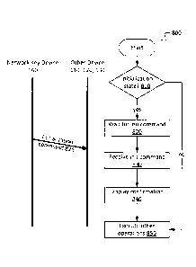
remote
21
CA 02853372 2014-06-04
switch device 110 returns to sleep mode 610, optionally after a predetermined
timeout
period.
[0092] FIG. 7 depicts an example of the general workflow 700 for a load
controller 120.
At 705, the load controller 120 is powered on and initialized. As with the
remote switch
device 110, initialization may occur either on initial power-up or on reset.
At 710, an
interrupt signal is received. In the case of the load controller 120, the
interrupt may arise
from a user actuation of a user control on the load controller 120 (e.g., a
button or switch
actuation), or from receipt of an RF message. At 715, the processor of the
load controller
120 determines whether the interrupt indicates a message initiating an
association or
pairing process with a remote switch device 110. If so, the association
process, described
in further detail below, starts at 720. If not, the load controller 110
determines at 725
whether the received interrupt indicates a CLEAR command. If so, the load
controller
clears its stored association table at 730 to remove all pairings. When the
association
table is cleared, the load controller 120 is no longer paired with any remote
switch
devices 110; however, it may still communicate with the network key device 140
or hub
130, if available.
[0093] If a CLEAR command was not received, then at 735 the load controller
120
determines whether a command to carry out an operation, such as ON/OFF, was
received.
11 so, the load controller 120 determines whether the command is valid at 740
(including
determining whether the load controller is paired with the remote switch
device
transmitting the command, if the command was transmitted by a remote switch
device).
If the command is valid, then the command is executed at 745.
[0094] FIG. 8 illustrates a possible initialization method 800 for a remote
switch device
110, load controller 120, or hub 130, implemented using the network key device
140. As
discussed above, initialization of a device can include an initial
configuration of the
components of the device for operation on the home area network 150. Once this
initial
configuration is complete, the processor of the device determines whether the
device is
still in an initialization state at 810. If it is not in an initialization
state, the device has
already been provisioned with a network key. The device is already configured
to carry
22
out other operations at 850. In the case of the remote switch device 110, as
mentioned
above, the device may enter a sleep mode while awaiting a further signal.
[0095] If the device 110, 120, 130 remains in the initialization state, at 820
it waits for an
initialization command from the network key device 140. At this stage, the
network key
device 140 can broadcast an initialization command 825 including the generated
network
key for receipt by any listening devices. At 830, the device 110, 120, 130
receives the
initialization command and saves the network key in memory, then optionally
signals the
user that initialization was completed 840. The signal may be an audible
signal or a visual
signal, such as illumination of a light emitting diode (LED). Once
initialization by the
network key device 140 is complete, the device 110, 120, 130 can carry out
other
operations 850.
[0096] Once devices are initialized and have a network key, at least one
remote switch
device 110¨load controller 120 set should be paired or associated. One
possible protocol
for pairing or associating a load controller 120 with one or more remote
switch devices
110 is illustrated by the load controller state diagram in FIG. 9. Generally,
since the
wireless light switch system is preferably configured to reduce power
consumption at the
remote switch devices 110, which draw current from an internal battery rather
than mains
power, the protocol described here does not require the remote switch device
110 to
receive any RF signals. The remote switch device 110 need only transmit one
message
containing its device identifier 222 and key 224.
[0097] As shown in FIG. 9, an initialized load controller 120 begins in a
Normal state
910, in which it is ready to receive commands. A user pair instruction 912 is
received by
the load controller 300, for instance by a key press or button press on the
load controller
300. The load controller then enters an Association Wait state 920, in which a
first
timeout is set and the load controller awaits a pairing communication from a
remote
switch device 110. The load controller may signal to the user that it is in
the Association
Wait state, by a visible or audible signal (e.g. a sequence of LED flashes or
a chirp). The
communication from the remote switch device 110 is initiated by the user,
again for
example by a key press or other user action. The pairing communication is a
message
23
CA 2853372 2020-02-06
CA 02853372 2014-06-04
containing at least the switch device's switch identifier 224 and device key
226. If the
timeout expires 924, or if an express "cancel" command is received from the
user 926
((for example, a different key press or button press on the load controller
120), the load
controller 120 exits the Association Wait state 920 and transitions back to
the Normal
state 910.
[0098] If the pairing communication 922 is received from the remote switch
device 110
before the timeout, the load controller 120 enters a Confirmation Wait state
930, during
which it waits a user confirmation that the pairing is to be completed. Again,
the load
controller 120 may issue a signal to the user that it is awaiting a
confirmation. A second
timeout is set; and again, if the timeout expires 934, or if a "cancel"
command is received
936, the Confirmation Wait state is cancelled and the load controller 120
returns to the
Normal state. If the pairing confirmation 932 is received within the timeout
period, then
the load controller 120 enters an Association Complete stage 940 in which it
completes
the pairing by storing the switch identifier 224 and the device key 226
received from the
remote switch device 110 in its association table. The load controller 120
then transitions
back to the Normal state 910.
[0099] The pairing procedure may be repeated on the same load controller 120
for a
plurality of remote switch devices 110 as described above, with the result
that the
association table stored in the load controller 120 will include identifiers
and keys for
multiple devices 110. The number of paired remote switch devices 110 may be
limited
only by available memory space. Similarly, the pairing procedure may be
repeated with
the same remote switch device 110 and multiple load controllers 120. As can be
seen
from the above protocol, the switch device 110 merely transmits its control
data, and is
not required to store any data pertaining to the pairing or the load
controller 120.
1001001 In a more robust pairing procedure, the remote switch device 110
may
include a receiver configured to receive messages from a load controller
during the
pairing process, confirming successful receipt of pairing information from the
remote
switch device 110. Thus, if the remote switch device 110 does not receive the
confirmation within a defined period of time, the device 110 can retransmit
its pairing
24
CA 02853372 2014-06-04
information until confirmation is received or the pairing process is aborted.
In still other
pairing procedures, a remote switch device 110 equipped with a transmitter may
initiate
the pairing process by transmitting an initial pairing inquiry message in
response to a user
command (e.g. a key press or sequence of inputs), rather than having the
pairing process
initiated by the user at the load controller 120. In some implementations, it
may not be
necessary for the user to physically manipulate the load controller, which may
be
advantageous in the case where the load controller has already been installed.
[00101] Still further, a remote switch device 110 that is equipped to
receive
information from a load controller 120 may itself store pairing data,
including load
controller identifiers and device keys for one or more load controllers, which
may be
provided in a manner analogous to that described above in respect of the
remote switch
devices 110. If the remote switch device 110 stores pairing data, it may then
address
messages to specific load controllers using the load controller's identifier
or a separate
address also obtained during pairing, rather than merely broadcasting signals
to all
receivers. Different methods for wirelessly pairing devices within and outside
a network
environment will be known to those skilled in the art.
[00102] Once the remote switch devices 110 and load controllers 120 in the
network 150 have been initialized and paired, the load controllers 120 are
ready to
receive commands from their paired remote switch devices 110 and the hub 130.
FIG. 10
provides an example method 1000 and accompanying communication diagram for
processing of received wireless messages by a load controller 120.
[00103] A device, such as a remote switch device 110, broadcasts a command
message 1005. As noted above, in the illustrated example system 100 the remote
switch
device 110 does not store pairing data; it simply broadcasts its commands for
receipt and
processing by any listening load controllers 120. The message includes, at a
minimum,
the remote switch device identifier 224 and the command to be executed by a
target
paired load controller 120. Each load controller 120 within range of the
remote switch
device 110 receives the message 1005 at step 1010. At 1015, the load
controller 120
attempts to validate the device identifier received in the message. At 1020,
the load
CA 02853372 2014-06-04
=
controller 120 determines whether the identifier in the message is valid;
i.e., that it is
stored in the load controller's association table as a paired device. If the
device identifier
is determined not to be present, then at 1035 the message is discarded. If,
however, the
identifier is found in the association table, the load controller 120 then
attempts to
validate the command received in the message at 1025.
[00104] In some embodiments, the message payload comprises more robust
data,
including, for example, redundancy bits and checksums, which may also be used
by the
receiving load controller 120 to check the integrity of the received message
at 1025. Also,
as discussed below, additional data such as the rolling code 228 may be
included in the
messages to improve security in the wireless light switch system, and so the
validation
step 1025 may include an attempt to verify this additional data as well. Some
or all of the
message payload may be encrypted by the remote switch device 110 using a
symmetric
cipher key established using pairing information shared with the load
controller 120
during pairing, in which case the validation step 1025 may include decryption
of the
message.
[00105] At 1030, the load controller 120 determines whether the command
received in the message is valid. If it is not valid, the command is discarded
at 1035 and
no responsive action is taken. If, however, the command is valid, then at 1040
the load
controller extracts the command and executes it. The load controller 120 thus
executes
commands received only from those remote switch devices 110 that were
"whitelisted" as
a result of the pairing procedure. The validation steps 1015-1020 and 1025-
1030 may be
implemented in the reverse order, although it is more expedient to check the
device
identifier first prior to decrypting and analysing a remainder of the message.
1001061 Since the remote switch device 110 broadcasts its messages in the
main
embodiment described herein, it is able to control a number of load
controllers 120 with a
single burst of data, rather than transmitting multiple addressed messages to
each paired
device, which increases communication time and drain on the remote switch
device
battery.
26
CA 02853372 2014-06-04
[00107] Example commands that may be sent by a remote switch device 110
configured to issue simple ON/OFF operation commands to a load controller 120
are set
out in Table 1 below:
Command Name Description
Switch OFF Switch off the light
Switch ON Switch on the light
Initiate Association Start association process (load
controller enters Association
Wait state)
Switch ON/OFF Change current status of the
light; if it is on, turn it off; if it
is off, turn it on
Erase Pairing Erase pairing with source
remote switch device (unlike
CLEAR, which clears all
pairings)
Table 1: Example Commands
[00108] The ability to transmit the aforementioned CLEAR command described
above may be restricted only to a designated master remote switch device 110
or the hub
130.
[001091 The hub 130 may be configured to send data to, and receive data
from, the
load controllers 120. The messages sent by the hub 130 may be broadcast,
multicast. or
unicast to many or only one load controller 120. For example, the hub 130 may
broadcast
an initial polling message to obtain identifiers for all controllers 120 on
the home area
network 150. Subsequently, the hub 130 can specifically address one or more
load
controllers 120 with a message containing an operation command, such as a
request for
status or to change the status of a light fixture. The hub 130 may also
transmit ON/OFF
and Status Change commands as described above in Table 1.
27
CA 02853372 2014-06-04
[00110] To reduce the likelihood of attacks on the home area network 150 or
individual load controllers 130 by malicious third parties, encryption and
rolling
(hopping) codes may be used to mitigate the risk of eavesdropping and replay
attacks.
These measures may be implemented together with a robust network packet
payload
including additional redundancy checks, such as the example set out in Table 2
below.
Content Offset (Bytes) Length Comment
Preamble 0-12 13bytes not encrypted
Synchronization 13-14 16 bits not encrypted
Switch Identifier 15-18 32 bits not encrypted
Command 19 8 bits encrypted
Rolling Code 20-23 32 bits encrypted
Checksum 24 8 bits encrypted; XOR of bytes 19-23
Battery Voltage 25-26 16 bits encrypted
Random Number 27-28 16 bits encrypted
Checksum 29 8 bits encrypted; XOR of bytes 25-28
Combination 30 8 bits encrypted; XOR of bytes 20, 25
Combination 31 8 bits encrypted; XOR of bytes 21, 26
Combination 32 8 bits encrypted; XOR of bytes 22, 27
Combination 33 8 bits encrypted; XOR of bytes 23. 28
Checksum 34 8 bits encrypted; XOR of bytes 30-33
CRC 35-36 16 bits not encrypted
Table 2: Switch Packet Payload Example
[00111] Encryption of some or all of the message payload may be
implemented, as
mentioned above, using a symmetric cipher key based on information provided by
the
28
CA 02853372 2014-06-04
remote switch device 110 to the load controller 120 at the time of pairing. In
the example
of Table 2, not all content of the message is encrypted. It will be
appreciated that many
different encryption algorithms and symmetric or asymmetric key arrangements
may be
employed; the following is but one example. Rather than using the device key
226 that
was provided by the remote switch device 110 to the load controller 120 on
pairing as the
encryption key, a separate cipher key may be generated at either the remote
switch device
110 or the load controller 120 from the device key 226 using an algorithm
configured at
both devices 110. 120, or agreed upon by both devices during the pairing. For
example,
the cipher key may be calculated as an exclusive-or combination of sets of
bytes of both
the device key 226 and the remote switch device's identifier 224. The cipher
key is then
optionally stored in memory at the remote switch device 110, or else computed
on the fly
when required by the remote switch device 110 to transmit a message.
Similarly, the load
controller 120 can store a copy of the cipher key in its association table, or
else compute
the cipher key upon receipt of a message that requires decryption. Since the
message
includes the switch identifier 226 (sent in the clear, as indicated in Table
2), when a
message is received, the load controller 120 can extract the switch identifier
from the
message to key into the association table to retrieve the corresponding cipher
key, or else
retrieve the corresponding data required to compute the cipher key.
[00112] As mentioned earlier, the message can include a rolling code that
is stored
at both the remote switch device 110 and the load controller 120 (at the
latter, in the
association table, in association with the corresponding switch device
identifier), and is
used by the load controller 120 to validate a received command. In the example
of Table
2 above, the rolling code is a 32-bit value that is retrieved from memory of
the remote
switch device 110 and inserted in the message payload then encrypted. Once the
message
is sent, the rolling code is incremented by 1 at the remote switch device 110
and stored.
[00113] When the message is received by a load controller 120 and the
device
identifier included in the message is validated, the load controller extracts
the rolling
code in the message and compares it to the rolling code 346 stored in its
memory 330 for
that device identifier. The rolling code received in the message is expected
to be greater
29
CA 02853372 2014-06-04
than the rolling code 346 stored at the load controller 120, since the remote
switch device
110 would have incremented its copy of the rolling code 228 after the previous
transmission.
[001141 It will be appreciated, however, that in some cases the rolling
code 228
stored at the remote switch device 110 may have been incremented by more than
1 since
the last time a transmission was received by the load controller 120, for
instance due to
error or a failed transmission. Thus, a range or window of permissible offsets
between the
rolling code received in the message and the rolling code stored at the load
controller 120
is defined. In one example, an "open" window, or offset between received and
stored
rolling codes at the load controller 120, is set at 16; thus, the received
rolling code in the
message must be greater than the stored rolling code 346, with an offset of no
more than
16 from the stored rolling code 346. If the received rolling code meets this
condition, the
load controller 120 may validate the received command, and stores the received
rolling
code in place of the stored rolling code 346, thus updating the stored rolling
code.
[00115] In some cases, the offset between the received rolling code and the
stored
rolling code 346 is outside the defined open window. In that case, the load
controller 120
will not execute the received command. However, the remote switch device 110
and the
load controller 120 may have fallen out of synchronization due to interference
or due to
one of the devices being moved out of range, so a re-synchronization window is
defined
for a select range of offsets greater than the offsets permitted within the
open window. If
the offset falls within the range of offsets permitted in the re-
synchronization window, the
rolling code received in the message is temporarily stored for the remote
switch device
110 in the association table. If a subsequent message is received from the
same remote
switch device 110 with a further rolling code with an offset from the
temporarily stored
value that falls within the open window range, then the newly received rolling
code is
stored for the remote switch device 110, and the controller 120 may then
execute the
received command in the new message. If, however, the offset of the first
received rolling
code falls outside both the open window and re-synchronization window, the
controller
neither executes the received command nor implements re-synchronization.
CA 02853372 2014-06-04
[00116] Table 3 illustrates possible windows for above rolling code
implementation for a rolling code 32 bits long, in which the range of possible
offsets is
zero to 232-1:
Window Offset Range
Open (rolling code valid) 1 to 16
Re-synchronization 17 to 231
Block (no action) 231+1 to 0
Table 3: Rolling Code Offset Windows
[00117] In Table 3, the open window for offsets for which received rolling
codes
are validated is the smallest window, covering only offsets from 1 to 16. The
re-
synchronization window then covers nearly half of the remaining possible
offsets greater
than 16. The "block" window, in which the offset between the received rolling
code and
the stored rolling code 346 is considered too great to permit re-
synchronization, covers
the remaining range of possible offsets, and includes the case where the
offset is zero.
The various ranges for these windows may be set arbitrarily. For example, the
range of 1
to 16 for the open window may be defined on the presumption that most
transmissions
from the remote switch device 110 to the load controller 120 will not fail.
This open
window may of course be set to cover a greater or smaller range of offsets
depending on
the overall performance of the wireless light switch system 100, and the
likelihood that a
transmission will fail. In a less robust system subject to high failure rates,
a larger open
window may be appropriate.
[00118] In one implementation, the rolling code value and other control
data are
stored in EEPROM at both the remote switch device 110 and the load controller
120. As
can be seen from the foregoing rolling code implementation, the rolling code
values
transmitted or received by a device are generally monotonically increasing by
a value of
1, and the changed value must be stored at both the transmitting and receiving
devices.
However, as those skilled in the art will appreciate, solid state storage
media such as
31
CA 02853372 2014-06-04
EEPROM can endure only a finite number of write-erase cycles before its
integrity is
degraded and the memory becomes unreliable. Common types of EEPROM currently
available have write-erase cycle limits ranging from about 100,000 to
1,000,000.
Assuming an average usage rate of about 100/operations per day for a remote
switch
device 110 or load controller 120, 100,000 write-erase cycles is equivalent to
about 2.74
years of use. This usage rate, which is possible in a high-traffic area,
results in an
expected EEPROM lifetime well below the expected lifetime for a home
automation
product. While memory rated with a higher duty cycle could be used instead,
this
substitution would increase the cost of manufacturing the device.
[00119] To address this problem, in a further embodiment, a wear-leveling
technique is applied to the EEPROM to extend the potential lifespan of the
memory
device. It may be noted that in the above rolling code implementation, the
least
significant bit (LSB) of the rolling code changes with each
transmission/reception, while
more significant bits change less frequently, meaning that when the memory
address
storing a LSB reaches its end of life, the second LSB may have half of its
life left, while
the third LSB may have three-quarters of its life remaining, and so on.
[00120] Different coding methods exist that permit write-erase cycles to be
distributed across different memory locations. For example, in a first coding
method,
referred to as "2-4 coding", two binary digits are used to represent four
numbers
according to the generation formula a', = al; a'0 = a, 0 ao, as set out in
Table 4:
Original Number 2-4 code
Decimal Binary
0 00 00
1 01 01
2 10 11
3 11 10
Table 4: 2-4 Coding
32
CA 02853372 2014-06-04
[00121] Thus, in the original set of binary numbers, the LSB changed on
every
count compared to the most significant bit (MSB), which changed only every
other count
in this example (i.e., half as frequently as the LSB). However, after encoding
with 2-4
code, the change rate of the LSB drops to every other count, like the MSB.
Using this
encoding, the potential lifespan of the LSB is now double the lifespan when
the
unencodcd values are stored. It will be appreciated by those skilled in the
art that the 2-4
coding is a trivial case of a general N-2N coding scheme that, when applied to
a series of
values increasing by 1, potentially extends the lifespan of memory by N times
compared
to unencoded values since each encoded bit position changes value only every N
counts
rather than every 1 count. Thus, in a 4-8 coding scheme, the LSB changes only
every four
counts rather than every count; and in an 8-16 coding scheme, the LSB changes
only
every eight counts. However, with increasing N the coding scheme introduces
increasing
redundancy (by one bit for 4-8 code, and four bits for 8-16 code). The 2-4
coding
scheme, however, does not add redundancy.
[00122] Another scheme that may be employed is a bit shift scheme that
again
distributes operations across all bits evenly. In a bit shift scheme, the
position of the LSB
is changed so that it occupies each location during a cycle. Thus, for
example, the bit
order rotates for a three-bit binary number increasing by 1, the bit order
rotates every
eight (23) counts from a2a1a0 to a1a0a2 to a0a2a1. At the end of three loops
through eight
number counts (from 000 to 111), every bit position will have changed the same
number
of times (14), thereby increasing the lifespan by approximately 1.714 times.
For N bit
shifts, after N loops the total number of changes or transitions Tb of each
bit can be
expressed as
[00123]
Tb = 21 + 22 + 23 =' = + 2N = 2 A (N + 1) ¨ 2
[00124] And the life expansion factor is calculated as
Ta N2N N2N-1
E = = ______
Tb 2N+1 ¨ 2 2N ¨ 1
33
CA 02853372 2014-06-04
[00125] where Ta is the total number counted. A similar principle may be
applied
to bytes.
[00126] Accordingly, in one embodiment, 2-4 coding and a byte shift are
combined and applied to the rolling code scheme described above. The 2-4 code
is
applied only to the lowest two bits of the rolling code, thereby doubling the
potential life
span of the EEPROM. In addition, each time the lowest 8-bit value overflows,
the byte
order is changed as follows: a3a2a1a0 4 aoa3a2a14 al aoa3a2 a2a1a0a3. The
life
expansion factor may then be calculated as:
4 x 256
E> ____________________ =7.817
¨ 128 + 1 + 1 + 1
[00127] which, when multiplied by the 2.74 year estimate above, yields a
lifespan
of about 21 years, which is more acceptable. Thus, by combining the foregoing
N-2N and
bit shifting schemes, and improvement in EEPROM performance may be realized.
[00128] Thus, in the case of a rolling code being incremented at the remote
switch
device 110, the remote switch device 110 may implement a method such as the
method
1100 shown in FIG. 11. At 1110, a number of blocks of memory (e.g., bytes) are
allocated to storage of the rolling code. In the example rolling code
discussed above, the
value to be stored is 32 bits long; thus, four blocks of one byte each in the
EEPROM are
allocated. A first value is then stored in the allocated memory at 1115, with
the least
significant byte of the first value being stored in a first block, the next
least significant
byte being stored in a second block, the second most significant byte being
stored in a
third block and the most significant byte in a fourth block. Subsequently, at
1120, the
initially stored value is read out of memory, and an instruction is received
to increment
the last stored value. In the rolling code example above, the value is read
out and added
to a message payload, and an instruction to increment the value is executed
after the
message is transmitted. The value is thus incremented.
34
[00129] However, prior to storage of the incremented value in the
allocated
memory blocks 1140, at least one permutation is applied to the incremented
value. First,
at 1125, the two least significant bits of the value are encoded according to
the 2-4 code
described above. As explained above, this results in a twofold increase in
memory life.
Next, a byte-wise shift is applied to the allocation of the bytes to the
designated memory
blocks according to a predetermined condition. At 1130, it is determined
whether the
increment resulted in an overflow of the least significant byte of the value.
If so, a cyclic
byte-wise shift is applied 1135 to reorder the bytes of the value with respect
to the
allocated memory blocks, as described above. Thus, the least significant byte
is assigned
to the previously-defined fourth block; the next least significant byte is
assigned to the
first block; the second most significant byte is assigned to the second block;
and the most
significant byte to the third block. If at 1130 it is determined that there is
no overflow of
the least significant byte, then no shift is implemented. A mapping may be
stored in in the
memory of the device correlating a logical address for each byte to the
physical address
of each block.
[00130] A similar procedure may be implemented at the load
controller 120,
although in the case of the load controller 120 the values may not be
incremented by 1.
[00131] As noted earlier, the size and/or electrical requirements of
some prior art
wall-mounted wireless switch devices impose limitations on the installer of
wireless light
fixture controls, since the device may require installation in an electrical
box either to
accommodate its bulk or to provide the necessary electrical wiring to the
building power
supply. The wireless light switch system 100 described herein may be
implemented using
remote switch devices and load controllers configured to provide flexibility
in installation
in new or old structures, and facilitate retrofitting of existing buildings. A
particular
example of a remote switch device and load controller is illustrated in FIGS.
12 through
23.
[00132] FIGS. 12 and 13 illustrate front and rear views of an
example remote
switch device 1200 configured to fit within a common single-gang or multi-gang
switch
plate, without requiring installation over an electrical box. The remote
switch device
CA 2853372 2020-02-06
CA 02853372 2014-06-04
1200 includes a casing comprising a base 1210 and a cooperating rocker-type
switch
shell 1240. The casing components may be manufactured of a thermoplastic
nylon,
polycarbonate, or any other material suitable for the manufacture of switch
plates that
does not significantly attenuate or block RF transmissions to or from the
transceiver of
the remote switch device. In this particular example, the rocker shell 1240
and the base
1210 together define a substantially closed enclosure that contains components
of the
remote switch device 1200, including the transceiver/transmitter and antenna,
memory,
microprocessor, battery, user control interfaces for both "ON" and "OFF"
positions of the
rocker shell 1240, and associated circuitry. In other embodiments, an
electrical control
other than a rocker switch may be provided.
[00133] The base 1210 includes a back plate with a substantially
rectangular lip or
sidewall 1212 projecting from the front surface of the plate. The back plate
and the
sidewall 1212 together define part of an enclosure 1213 (indicated in FIG.
16). The
sidewall 1212 can be substantially continuous as illustrated in the
accompanying
drawings, and defines part of an enclosure sized to receive components as
shown in FIG.
16, and the rocker shell 1240. In some examples, the sidewall 1212 may
comprise a
number of distinct projections that are not continuous, but still
substantially define the
enclosure. As will be seen more clearly in FIG. 14, in this particular example
the sidewall
1212 is sized to fit within the electrical control aperture of a typical,
commercially
available Decora or similar switch plate. For example, a Leviton Decora
brand
Designer Wallplate model 80401-GFI from Leviton Manufacturing Co., Inc., New
York,
USA, has an aperture of 33.2mm wide by 66.8mm high. The exterior dimensions of
the
sidewall 1212 in one implementation of the remote switch device 1200 as shown
in FIG.
12 is 33mm wide by 66.5mm high. The exterior dimensions may of course be sized
as
required to fit within differently-sized apertures of alternative switch
plates.
1001341 Flanges 1214, 1216 extend from the top and bottom, respectively, of
the
base 1210 and provide bores 1220 and slots 1222 for receiving fasteners (not
shown) for
mounting the remote switch casing to a switch plate and/or a wall or existing
electrical
box (although as noted above, mounting on an electrical box is not required).
The slots
36
CA 02853372 2014-06-04
1222 may be provided with a counterbore or may be otherwise recessed from the
front
surface of the back plate to accommodate the depth of a screw head.
Alternatively, the
remote switch device 1200 can be affixed to a wall or other surface using
double-sided
tape or another adhesive mounting means. The back surface of the base 1210 in
the
implementation shown in the figures therefore provides a substantially flat
area to which
an adhesive can be applied for mounting on a flat surface.
[00135] Turning to FIGS. 14 and 15, the assembly of the remote switch
device
1200 in a typical single-gang Leviton Decorat switch plate 30 (depicted in
phantom
lines) is shown. Seen from the front face 32 of the switch plate 30, the
sidewall 1212 and
rocker shell 1240 protrude through the aperture 34 of the switch plate 30. The
rear
surface 33 of the switch plate 30 is recessed from the wall-contacting rear
surface 36 of
the switch plate 30, defining a space for receiving the base 1210 of the
remote switch
device 1200. The flanges 1214, 1216 are therefore retained behind the switch
plate 30.
Screws 38 pass through bores provided in the switch plate 30 and the bores 38
in the base
1210. The thickness of the flanges 1214, 1216 is selected in order to permit
the switch
plate 30 to be mounted against a flat surface without creating a gap between
the surface
and the wall-contacting rear surface 36. It will be understood that multiple
remote switch
devices 1200 may be similarly mounted in a multi-gang switch plate, or that a
remote
switch device 1200 can be mounted in a multi-gang switch plate in combination
with a
traditional wired switch or other electrical control or outlet.
[00136] The remote switch device 1200 is shown in exploded view in FIG. 16.
The
enclosure 1213 receives a circuit board 1380 bearing components of the remote
switch
device 1200 and elastically deformable contact pads or actuators 1350. Tabs
1218
extending from the interior surface of the sidewall 1212 retain the circuit
board 1380 in
position. The enclosure is further defined by a rocker shell 1240, which is
formed of two
oblique faces 1241a, 1241b (indicated in FIG. 17) meeting at a central pivot
axis. In this
example, the switch has two positions (an "ON" and "OFF") associated with
depression
of either oblique face. In other examples of rocker switches, the rocker may
comprise
only one face that is pivotably mounted at one end to a base, not shown in the
37
accompanying drawings. It will be appreciated that such other types of rocker
switches
may be adapted in accordance with the teachings herein. The faces 1241a, 1241b
are
described as "oblique" as they are both oblique to one another and to a plane
of the base
1210. As can be seen more clearly in FIG. 17, on the inside of the rocker
shell 1240 the
oblique faces 1241a, 124 lb define an internal angle greater than 1800
.
[00137] At least one sidewall 1243 depends from the oblique walls of
the rocker
shell 1240. In this example, the sidewall 1243 of the rocker shell 1240 is
sized to fit
within the interior sidewall 1212 so as to retain the circuit board 1380 and
actuators 1350
within the enclosure. The sidewalls 1243 of the rocker switch are grooved 1242
at the
switch's fulcrum or pivot axis. Posts or lugs 1219 projecting from either
interior side of
the base sidewall 1212 ride in the grooves 1242 when the casing is assembled
to permit
the rocker switch to move in a rocking motion between an "ON" position (e.g.,
depression of an upper portion of the rocker switch) and an "OFF" position
(e.g.,
depression of a lower portion of the rocker switch). Cutouts 1244 in the
rocker shell
accommodate the tabs 1218. In the aforementioned implementation, the at least
one
sidewall 1243 is substantially straight, but the outer surface of the sidewall
1243 at the
ends of the rocker shell 1240 (i.e., the ends that are substantially parallel
to the pivot axis)
may be slightly bevelled to minimize tubbing between the sidewall 1243 and the
base
sidewall 1212 as the rocker shell 1240 travels between "ON" and "OFF"
positions. It can
be seen in FIGS. 16 and 17 that the sidewall 1243 of the rocker shell 1240 has
a greater
depth closer to the pivot axis than at the ends of the rocker shell 1240.
[00138] As can be seen in the rear perspective view of the rocker
switch shell 1240
in FIG. 17, the interior face is provided with sets of posts 1245, 1246. These
posts 1245,
1246 provide engagement means for retaining the actuators 1350 in position.
[00139] The base 1210 and its sidewall 1212, and the sidewall 1243
and oblique
walls 1241a, 1241b of the rocker shell 1240, together define the enclosure
1213. It will be
appreciated by those skilled in the art that as a result of the general
configuration of the
rocker shell 1240 and its pivoting action when mounted on the base 1210, the
enclosure
shape will change when the remote switch device 1200 actuated and released. In
the
38
CA 2853372 2020-02-06
CA 02853372 2014-06-04
aforementioned implementation, the base sidewall 1212 is approximately 2.25mm
thick,
resulting in the enclosure 1213 having a width of approximately 28.5mm by
62.5mm
high. The depth of the enclosure on the base 1210 is approximately 7mm, and
the overall
depth of the base 1210 is approximately 9mm. The base sidewall 1212 may
project only
by about 5.5 to 6mm from the base 1210. The overall height and width of the
rocker shell
1240 is approximately 62mm by 28mm with an approximately 2mm thick sidewall
1243
and oblique walls 1241a, 1241b. On the interior of the rocker shell 1240, the
sidewall
1243 depth ranges from approximately 4.5mm closer to the pivot axis to 3.5mm
closer to
the ends (excepting any cutouts to accommodate other parts, such as the
grooves 1242).
The overall dimensions of the remote switch device 1200, including the flanges
1214,
1216, are approximately 104mm high by 35mm wide with a depth of lOmm.
[00140] The actuators 1350 are shown in greater detail in FIGS. 18A to 18C.
The
actuators may be referred to as "dome-type" as they operate on a similar
principle as a
keyboard dome switch. Generally, the actuators 1350 comprise a polygonal dome-
type
structure housing an interior stem or nub bearing a conductive pad, such that
when force
is applied to a bearing surface on the exterior of the structure is
compressed, the interior
nub and the conductive pad are displaced towards the rear of the actuator as
to come into
contact with an adjacent switch contact.
[00141] In the depicted example, an actuator 1350 is manufactured using a
suitable
material that provides an appropriate amount of elastic deformation, such as
silicone or
polyurethane. The structures comprise generally solid rectangular-shaped keys
or contact
members 1353, 1363 supported by a collapsible collar 1354, 1364, respectively,
which in
this example comprise angled walls extending from a front face 1351 of a base
of the
actuator. Each contact member 1353, 1363 is provided with cooperating
engagement
means corresponding to the engagement means provided on the interior of the
rocker
switch shell 1240. In this particular example, one of each type of post 1245,
1246 is
provided at each of the "ON" and "OFF" positions of the rocker switch, so the
contact
members 1353, 1363 are therefore provided with corresponding recesses 1356,
1366
matching the shape of the corresponding shape of the post 1245, 1246. The
posts in this
39
CA 02853372 2014-06-04
example vary in shape so as to ensure that the actuators 1350 are correctly
aligned in the
remote switch device 1200.
[00142] The junction of the rectangular keys 1353, 1363 and the collapsible
collars
1354, 1364 define a bending perimeter. On the rear face 1352 of the actuator
1350,
shown in FIG. 18B, the angled walls 1354, 1364 define cavities. Nubs 1358,
1368
protrude from the rear side of the rectangular key into the interior of a
cavity, but do not
extend all the way to the rear surface 1352 when the actuator 1350 is in an
unstressed
state. One nub is provided with a pad of graphite or another suitable
conductive material,
as indicated by the shading in FIG. 19B. The nubs in this example protrude
from the
contact members 1353, 1363 into the collapsible collar 1354, 1364, but in some
examples
the nubs are not included, and the conductive pad 1368 is provided on an
interior surface
of the contact member 1363 within the collar 1364.
[00143] When the remote switch device 1200 is assembled, the rear surfaces
of the
actuators 1350 are in contact with the circuit hoard and are positioned such
that
conductive pads provided on the actuators 1350 are substantially aligned with
corresponding switch contacts on the circuit board, without contacting the
switch
contacts. The rocker switch may be considered to be in a neutral position (in
neither an
"ON" or "OFF" position, although the associated light fixture may be in an ON
or OFF
state). The switch contacts are not shown in the figures, but may comprise a
pair of
circuit traces on the circuit board. When the rocker shell 1240 is depressed
by a user at
either the "ON" position or "OFF" position, the posts 1245, 1246 in that
position press on
the corresponding contact members 1353, 1363, causing the actuator structure
to collapse
along the bending perimeter and force the contact member and conductive pad
move
through the space defined within the collar 1354, 1364 and the base of the
actuator 1350
to contact the circuit traces, thus closing a circuit on the board. The
pressure is applied
via the rocker shell 1240, and it will be noted from the cross-sectional view
in FIG. 18C
that the upper bearing surface of the contact member 1363 is substantially
flat and
inclined to generally correspond to the oblique configuration of the rocker
shell face.
When the pressure is applied to the rocker shell 1240, the rocker shell 1240
contacts an
CA 02853372 2014-06-04
area of the upper surface of the contact member 1353, 1363 rather than merely
a single
point, which may be the case with a true dome structure. The greater area of
contact
provides for better contact between the conductive pad and the switch contact
on the
circuit board. When pressure on the rocker shell 1240 is released, the
actuator 1350 will
return to its normal state, pushing the rocker shell 1240 back to its neutral
position.
[00144] This response is unlike a conventional electromechanical rocker
light
switch, which will be latched in the "ON" or "OFF" position until the switch
is actuated
again, thereby providing the user with a form of tactile and visual feedback
indicating
that the user's action on the switch was successful. However, the slight
resistance of the
silicone or polyurethane actuators 1350 and collapse of the actuator structure
under user
pressure provides a form of tactile feedback that replaces the tactile feeling
of operating a
conventional rocker switch.
[00145] In one implementation, the maximum height of the actuator 1350 is
approximately6.75mm, including the contact member 1353, 1363 supported on an
angled
collar 1354, 1364 approximately 1.5mm in height at an angle of about 50 , in
turn
supported on a base of about 1.5mm thickness. The actuator 13150 can be
accommodated
within the enclosure 1213 of the aforementioned implementation of the remote
switch
device 1200 when the rocker shell 1240 is in a neutral or non-actuated state.
In this
particular implementation, the contact member1363 has an upper bearing surface
inclined
at about 3-4 .
[00146] It may be note that the actuators 1350 depicted in the figures
include a pair
of contact members and collars, although it is only necessary, given the
arrangement of
the circuit in this example, for each actuator 1350 to comprise only one
contact member
assembly. This particular configuration of the actuator 1350 facilitates
manufacture and
installation, as the sets of engagement means (e.g., recesses 1356, 1366)
ensure that the
actuators 1350 are aligned in the correct direction when installed in the
device 1200.
[00147] As can be seen in FIG. 14, the external configuration of the remote
switch
device 1200 is such that the device 1300, once assembled in a conventional
switch plate
41
30, resembles other rocker switch devices in appearance. Further, the
dimensions of the
remote switch device 1200 permit the remote switch device-switch plate
combination to
be mounted on any surface, whether or not an electrical box is available. This
versatility
is realized in part by the low profile and arrangement of the circuit
components on the
circuit board 1380, which permit the depth of the enclosure 1213 to be reduced
compared
to enclosures in prior art wireless light switches.
[00148] FIG. 19 is a schematic depicting the relative positions of
major
components of the remote switch device 1200, as they may be mounted on a
printed
circuit board. Switch contact traces 1388 are positioned proximate to the ends
(i.e., the
"top" and "bottom", when the remote switch device is mounted in a vertical or
portrait
orientation) of the circuit board 1380. At one end of the board 1380,
proximate to one of
the contact traces 1388, is a circuit board trace antenna 1386. The antenna
may have any
suitable configuration; as those skilled in the art appreciate, the design of
the antenna is
determined by factors such as available space and the intended transmission
wavelength.
The transceiver, processor, and memory of the remote switch device in this
case is
provided by a SoC 1390 positioned in a middle portion 1382 of the circuit
board 1380.
Occupying the most area on the circuit board is a lithium coin-type battery
1384, also
located in the middle portion of the circuit board 1380. The battery 1384 is
therefore
retained in the enclosure 1213 substantially at or near the pivot axis of the
rocker shell
1340, where the angle of the oblique walls 1241a, 1241b of the rocker shell
1240
protrudes towards the base 1210 of the remote switch device 1200. The battery
1384 is
retained on the circuit board 1380 by a low profile holder 1392, indicated in
FIG. 16,
which comprises a retaining belt or pocket mounted at either side to the
circuit board
1380 over a contact provided on the circuit board, such that the battery 1384
can be slid
in and out of position on the contact. In one implementation, no surface-
mounted
components are provided near the ends of the board 1380, so the rear surfaces
of the
contact pads 1350 may rest flush against the circuit board.
[00149] The schematic of FIG. 19 omits other components that may be
required
for proper operation of the remote switch device 1200 such as resistors,
capacitors,
42
CA 2853372 2020-02-06
CA 02853372 2014-06-04
oscillators, and the like, as well as connecting traces; these additional
components,
however, generally occupy smaller volumes of space or circuit board area than
the major
components illustrated in FIG. 19. Overall, the total depth of the circuit
board and
components, together with the actuator 1350, fits within the dimensions of the
enclosure
1213 given above. Thus, with appropriate selection and arrangement of circuit
components, a remote switch device can be provided that permits flush wall-
mounting
using a commonly available Decora brand or similar switch plate, without
requiring the
use of an electrical box or cutout in the wall to accommodate the remote
switch
components.
[00150] A companion load controller 2000 is illustrated in FIGS. 20 to 23.
FIG. 20
is a perspective view of an assembled load controller 2000. The electrical
components of
the controller 2000 are contained in a an enclosure comprising, in this
example, a lid
2010 and a base 2020, which may be manufactured from the same types of
materials as
the remote switch device 1200. In this example the lid 2010 is latched to the
base 2020 by
cooperating locking components 2012, 2022.
[00151] An antenna port 2026, visible in FIG. 23, is provided in a front
wall 2021
of the load controller 2000. The antenna port 2026 position is selected to
align with a
junction box knockout when the load controller 2000 is installed in the
junction box. To
provide this alignment and maintain the load controller 2000 in fixed position
once
installed in the electrical box, a fitting 2024 such as a threaded nipple is
provided on the
wall 2021 of the load controller 2000, and the antenna port 2026 is positioned
within the
area defined by the fitting 2024. The fitting 2024 is sized to fit in the
junction box
knockout. As those skilled in the art will appreciate, knockouts of different
dimensions
may be provided in a junction box; the fitting 2024 may be sized to fit in any
one of these
dimensions. A wire or whip antenna 2056 extends from the interior of the
enclosure,
through the exit port 2026, to the exterior of the load controller. The
enclosure also
provides ports 2051. 2053 for one or more buttons or other user controls as
well as ports
2028 (also shown in FIG. 23) for phase, neutral, and control wires for wiring
to the light
43
CA 02853372 2014-06-04
fixture. Excluding the fitting 2024 and protruding wires, the load controller
2000 in these
examples has dimensions of approximately 55mm long by 47mm high by 39mm deep.
[00152] FIGS. 21 and 22 illustrate the load controller 2000 as it may be
installed in
a standard sized octagonal junction box 40. One standard size octagonal
electrical box
has dimensions of about 100mm in length and depth by about 54mm deep. It can
be seen
from the top and side views of these figures that the load controller 200
within the
junction box 40, with more than half of the junction box's volume remaining to
accommodate wires and connectors.
[00153] FIG. 23 depicts the load controller 200 in an exploded view. In
this view,
the ports 2028 for light fixture wiring (wires not shown in the figures) and
the antenna
port 2026 are visible in the base 2020. The fitting 2024 is mounted on the
exterior of the
front wall 2021. The position of the antenna port 2026 is coincident with the
area
surrounded by the fitting 2024.
[00154] Contained within the enclosure is a circuit board 2050 generally
comprising the components described in connection with FIG. 3. The circuit
board in this
example sits vertically within the enclosure, with the bottom surface (i.e.,
opposite the
surface on which circuit components are generally mounted) facing the front
wall 2021.
The antenna 2026 extends from the bottom surface of the circuit board 2050
through the
antenna port 2026 and fitting 2024.
[00155] To install, once the load controller 2000 has been initialized, it
is placed in
the light fixture junction box 40 with the fitting 2024 and antenna 2056
extending
through a knockout or other aperture in the junction box 40. The neutral and
line wires
leading off the controller 2000 are maretted (i.e., capped) with the
corresponding building
wiring, and the load wire from the controller 2000 is connected to the light
fixture. It will
be appreciated by those skilled in the art that because the antenna 2056
extends via the
antenna port 2026 and fitting 2024 beyond the junction box 40, it will not be
shielded by
the junction box 40, even if the junction box is made of metal. Assuming that
other
materials in the surrounding area do not unduly attenuate or block signals to
or from the
44
CA 02853372 2014-06-04
antenna, there is no need to replace existing metal junction boxes 40 with
plastic. This
facilitates retrofitting of existing lighting fixtures, and permits the
installer to use more
durable metal rather than plastic junction boxes. The load controller 2000 can
then be
paired with one or more remote switch devices 120 as described above.
[00156] Throughout the specification, terms such as "may" and "can" are
used
interchangeably and use of any particular term should not be construed as
limiting the
scope or requiring experimentation to implement the claimed subject matter or
embodiments described herein. Further, the various features and adaptations
described in
respect of one example or embodiment in this disclosure can be used with other
examples
or embodiments described herein, as would be understood by the person skilled
in the art.
[00157] Code configured to provide the systems and methods described above
may
be provided on many different types of electronic device-readable media
including
physical or non-transitory data storage mechanisms (e.g., CD-ROM, RAM, flash
memory, computer hard drive, etc.) that contain instructions for use in
execution by a
processor to perform the methods' operations and implement the systems
described
herein.
[00158] It should be understood that any processing or communication steps
described herein may be altered, modified and/or augmented and still achieve
the desired
outcome. Various functional units may be implemented in hardware circuits such
as
custom VLSI circuits or gate arrays; field-programmable gate arrays;
programmable
array logic; programmable logic devices; commercially available logic chips,
transistors,
and other such components. Modules implemented as software for execution by a
processor or processors may comprise one or more physical or logical blocks of
code that
may be organized as one or more of objects, procedures, or functions. The
modules need
not be physically located together, but may comprise code stored in different
locations,
such as over several memory devices, capable of being logically joined for
execution.
Modules may also be implemented as combinations of software and hardware, such
as a
processor operating on a set of operational data or instructions.
CA 02853372 2014-06-04
[00159] A portion of the disclosure of this patent document contains
material
which is or may be subject to one or more of copyright, design patent,
industrial design,
or unregistered design protection. The rights holder has no objection to the
reproduction
of any such material as portrayed herein through facsimile reproduction of the
patent
document or patent disclosure, as it appears in the Patent and Trademark
Office patent
file or records, but otherwise reserves all rights whatsoever.
46