Note: Descriptions are shown in the official language in which they were submitted.
CA 02853420 2014-04-24
DocketNo.PMHA-14001-POT
1
DESCRIPTION
DIRECT REDUCED IRON MANUFACTURING SYSTEM
Field
[0001] The present invention relates to a direct reduced
iron manufacturing system.
Background
[0002] Iron ore such as fine ore and lump ore is reduced
in solid phase at, for example, approximately 1000 C by
synthesis gas to obtain direct reduced iron (DRI: Direct
Reduced Iron). The direct reduction iron making method is
low in usage rate of a reducing gas in a reduction furnace.
Therefore, reduction furnace flue gas is returned to the
reducing gas flow to be reused. Accordingly, efficiency is
increased.
Water (H2O) and carbon dioxide (CO2) that are produced
in the reduction furnace are inert in the reduction furnace.
Therefore, it is necessary to remove them for reuse. The
water is removed in a cooler or scrubber, and the carbon
dioxide in, for example, a removal unit with an amine-based
solvent or the like (Patent Literature 1).
Citation List
Patent Literature
[0003] Patent Literature 1: Japanese Patent Application
National Publication (Laid-Open) No. 2001-520310
Summary
Technical Problem
[0004] However, a solvent degradation product of the
amine-based solvent is generated by carbon monoxide (CO)
and trace metal components, which are specific to fuel gas
from a direct reduced iron making furnace, or heat in a
reboiler of a regenerator in an acid gas removal unit. The
resulting problems are not only that foaming occurs, which
reduces acid gas removal performance and makes the
CA 02853420 2014-04-24
DocketNo.PMHA-14001-PCT
2
operation difficult, but also that corrosion degradation of
the acid gas removal unit occurs.
[0005] A known direct reduction process is controlled by
replacing the amine-based solvent with a new one to reduce
the concentration of the degradation products. Especially,
a direct reduced iron making furnace system needs to
replace the amine-based solvent with high frequency, which
results in a problem that a large amount of a solvent is
consumed.
[0006] Hence, a measure that eliminates the need of
frequent replacement of the amine-based solvent and enables
the promotion of a dramatic reduction in the amount of use
of the amine-based solvent compared with before is desired
to appear.
[0007] Considering the above problem, the present
invention tackles a problem providing a direct reduced iron
manufacturing system that can promote a reduction in the
amount of use of an acid gas absorbent upon removal of acid
gas such as CO2 in the flue gas from the direct reduced
iron making furnace.
Solution to Problem
[0008] According to a first aspect of the present
invention in order to solve the problems, there is provided
a direct reduced iron manufacturing system including: a
direct reduction furnace for reducing iron ore directly
into reduced iron using a high-temperature reducing gas
including hydrogen and carbon monoxide; an acid gas removal
unit including an acid gas component absorber for removing,
with an absorbent, an acid gas component in a reduction
furnace flue gas discharged from the direct reduction
furnace, and a regenerator for releasing the acid gas; and
a degradation product removal unit for separating and
removing a degradation product in the absorbent used by
CA 02853420 2016-02-09
, 53609-72
3
circulating between the acid gas component absorber and the
regenerator.
[0009] According to a second aspect of the present
invention, there is provided the direct reduced iron
manufacturing system according to the first aspect, further
including: a bypass circuit for bypassing a part of a lean
solvent to be returned from the regenerator to the absorber;
and a filter interposed in the bypass circuit.
[0010] According to a third aspect of the present invention,
there is provided the direct reduced iron manufacturing system
according to the first or second aspect, further including: an
introduction line for introducing the reduction furnace flue
gas into the acid gas removal unit; a heat exchanger,
interposed on the introduction line, for heat exchanging the
reduction furnace flue gas; a bag filter provided upstream of
the heat exchanger; and a scrubber provided downstream of the
heat exchanger.
[0011] According to a fourth aspect of the present
invention, there is provided the direct reduced iron
manufacturing system according to any of the first to third
aspects, wherein the acid gas absorbent has a low boiling
point.
[0012] According to a fifth aspect of the present invention,
there is provided the direct reduced iron manufacturing system
according to any of the first to fourth aspects, wherein the
high-temperature reducing gas is a gas produced from natural
gas, coal gasification gas, or coke oven gas.
CA 02853420 2016-10-20
53609-72
3a
[0012a] A further aspect of the invention relates to a direct
reduced iron manufacturing system comprising: a gas heater for
heating a gas to produce a reducing gas; a direct reduction
furnace for reducing iron ore directly into reduced iron using
the reducing gas comprising hydrogen and carbon monoxide; an
acid gas removal unit including an acid gas component absorber
for removing, with an absorbent, an acid gas component in a
reduction furnace flue gas discharged from the direct reduction
furnace, and a regenerator for releasing the acid gas; a
degradation product removal unit for separating and removing a
degradation product in the absorbent used by circulating
between the acid gas component absorber and the regenerator; a
purified gas supply line for joining a purifying gas purified
in the absorber and comprising hydrogen and carbon monoxide to
the gas; and a recovery gas supply line for supplying a
recovery gas comprising 002 and H2S released from the
regenerator into the gas heater.
Advantageous Effects of Invention
[0013] According to the present invention, degradation
products in an acid gas absorbent circulating through an
absorber and a regenerator can be separated in a
CA 02853420 2014-04-24
DocketNo.PMHA-14001-PCT
4 *
degradation product removal unit. Accordingly, the need of
frequent replacement of the acid gas absorbent is
eliminated, and it is possible to promote a dramatic
reduction in the amount of use of the solvent compared with
before.
Moreover, the concentration of the solvent degradation
products is continuously controlled. Accordingly, it is
possible to suppress the occurrence of foaming, achieve
stable operation, and also suppress corrosion of equipment.
The stabilization of operation makes it possible to
achieve the safe operation of the entire direct reduced
iron process, and a reduction in cost by a reduction in the
consumption amount of the solvent.
Furthermore, heat in the direct reduced iron process
system is used to operate the degradation product removal
unit. Accordingly, additional energy consumption is not
required, which is economic.
Brief Description of Drawings
[0014] FIG. 1 is a schematic diagram of a direct reduced
iron manufacturing system according to the first embodiment.
FIG. 2 is a schematic diagram of a direct reduced iron
manufacturing system according to the second embodiment.
FIG. 3 is a schematic diagram of a direct reduced iron
manufacturing system according to the third embodiment.
FIG. 4 is a schematic diagram of a direct reduced iron
manufacturing system according to the fourth embodiment.
FIG. 5 is a schematic diagram of another direct
reduced iron manufacturing system according to the fourth
embodiment.
FIG. 6 is a schematic diagram of a direct reduced iron
manufacturing system according to the fifth embodiment.
FIG. 7 is a schematic diagram of another direct
reduced iron manufacturing system according to the fifth
CA 02853420 2014-04-24
DocketNo.PMHA-14001-PCT
embodiment.
Description of Embodiments
[0015] Hereinafter, the present invention will be
described in detail with reference to the drawings. The
5 present invention is not limited by the embodiment(s).
Moreover, if there is a plurality of embodiments, the
present invention includes their combination. Moreover,
the components in the embodiments include components that
can easily be assumed by those skilled in the art or
substantially the same components.
First Embodiment
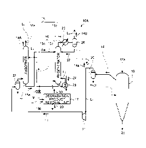
[0016] A direct reduced iron manufacturing system
according to an embodiment by the present invention will be
described with reference to the drawing. FIG. 1 is a
schematic diagram of the direct reduced iron manufacturing
system according to a first embodiment. As illustrated in
FIG. 1, a direct reduced iron manufacturing system 10A
includes a direct reduction furnace (hereinafter referred
to as the "reduction furnace") 13 that reduces iron ore 12a
directly into reduced iron 12b using a high-temperature
reducing gas (hereinafter referred to as the "reducing
gas") 11 including hydrogen and carbon monoxide, an acid
gas removal unit 16 having an acid gas component absorber
(hereinafter referred to as the "absorber") 16a for
removing acid gas components (CO2, H2S) in a reduction
furnace flue gas 14 discharged from the direct reduction
furnace 13 with an acid gas absorbent (hereinafter referred
to as the "absorbent") 15 such as an amine-based solvent,
and a regenerator 16b for releasing the acid gas and
regenerating the absorbent 15, and a degradation product
removal unit 17 for separating and removing degradation
products in the absorbent 15 that is used by circulating
through the absorber 16a and the regenerator 16b.
CA 02853420 2014-04-24
DmketNo.FWNA-14001-POT
6 '
In FIG. 1, a reference numeral 15a denotes a rich
solvent, 15b a lean solvent, 20 a scrubber, 21 a compressor,
22 a cooling scrubber, 23 a reboiler, 24 steam, 25 a cooler,
26 a gas-liquid separator, 27 condensed water, L1 a gas
supply line for introducing the reduction furnace flue gas
14 into the acid gas removal unit 16, L2 a rich solvent
line, L3 a lean solvent line, L4 a lean solvent branch line,
L5 a reboiler line for circulating the lean solvent in a
lower part of the regenerator, L6 a gas release line, L7 a
condensed water line, L8 a recovery gas discharge line, L9
a purified gas discharge line, and L10 a gas discharge line.
The reducing gas 11 is heated up to a predetermined
high temperature (for example, 900 to 1,050 C) when being
introduced into the reduction furnace 13.
[0017] The iron ore 12a is supplied from a top of the
reduction furnace 13 where the reducing gas 11 is
introduced, and the supplied iron ore 12a moves toward the
furnace's bottom side. At this point in time, the iron ore
(iron oxide) 12a is reduced into the reduced iron 12b by
hydrogen (H2) and carbon monoxide (CO), which are main
components of the reducing gas 11, in countercurrent
contact with the high-temperature reducing gas 11
simultaneously supplied from a side of the reduction
furnace 13 as well as the hydrogen (H2) and carbon monoxide
(CO) are respectively inverted into water (H20) and carbon
dioxide (CO2).
The reduced iron ore 12a is taken out as the reduced
iron 12b from a lower side of the reduction furnace 13.
[0018] Moreover, the hydrogen (H2) and carbon monoxide
(CO) in the reducing gas 11 are not used up in the
reduction furnace 13, and the majority of the hydrogen (H2)
and carbon monoxide (CO) stays unused and discharged as the
reduction furnace flue gas 14 into the gas supply line Ll.
CA 02853420 2014-04-24
DocketNo.PMHA-14001-PCT
7
[0019] The reduction furnace flue gas 14 from the
reduction furnace 13 contains dust generated from the
reduction furnace 13, such as iron powder, which has an
adverse effect on the operation of the acid gas removal
unit 16 connected on the downstream side. Therefore, the
scrubber 20 removes the dust as well as the water (H20)
produced in the reduction furnace 13.
[0020] The reduction furnace flue gas 14 is pressurized
by the compressor 21 interposed on the gas supply line 1,1
and then introduced into the cooling scrubber 22. In the
cooling scrubber 22, the gas is decreased in temperature by
cooling water, and then introduced into the absorber 16a of
the acid gas removal unit 16.
In the absorber 16a, the acid gas of CO2 and H2S is
removed from the reduction furnace flue gas 14 by a
chemical absorption reaction of the absorbent 15 to form a
purified gas 14A from which the acid gas has been removed,
and the purified gas 14A is discharged into the purified
gas supply line L9 from a top side.
The purified gas 14A contains the unused H2 and CO and
accordingly it may be configured such that the purified gas
14A joins the reducing gas 11 and is reused as the reducing
gas 11 (which is described below).
[0021] In order to avoid the accumulation of CH4 and N2
being system inert components contained in the reduction
furnace flue gas 14 in the system, it is configured such
that a part 14a of the gas emitted from the scrubber 20 is
discharged out of the system through the gas discharge line
L10 branching from the gas supply line L1 on a downstream
side of the scrubber 20.
[0022] In the absorber 16a in the acid gas removal unit
16, the absorbent 15 absorbs and removes the acid gas
components of CO2 and H2S from among CO, H2, CO2, and H2S
CA 02853420 2014-04-24
DmketNaPMHML4N)1-PCT
' 8
contained in the reduction furnace flue gas 14.
The absorbent 15 that has absorbed CO2 and H2S in the
absorber 16a is referred to as the rich solvent 15a. The
rich solvent 15a is supplied to the regenerator 16b side
through the rich solvent line L2. The rich solvent 15a
introduced into the regenerator 16b releases the absorbed
CO2 and H2S in the regenerator by the heat of steam heated
in the reboiler 23 to form the lean solvent 15b. The lean
solvent 15b is returned again to the absorber 16a through
the lean solvent line L3 to be circulated and reused.
[0023] A cooling part (not illustrated) for removing the
entrained absorbent in the purified gas 14A is provided on
an upper side of the absorber 16a.
Moreover, in the regenerator 16b, a recovery gas 14B
mainly including the CO2 and H2S that have been released
from the rich solvent 15a is discharged out of the system
from its top through the gas release line L6.
[0024] The recovery gas 14B is cooled in the cooler 25
interposed on the gas release line L6. The condensed water
27 is then separated from the recovery gas 14B in the gas-
liquid separator 26. The separated condensed water 27 is
returned into the regenerator 16b through the condensed
water line L7.
[0025] The reduction furnace flue gas 14 from the
reduction furnace 13 contains a lot of CO and iron
components, and those that cannot be removed in the
scrubber 20 interposed on the gas supply line L1 may mix in
the acid gas removal unit 16.
Moreover, a part of the absorbent 15 causes a chemical
reaction with such CO and iron components by the long-time
operation and accordingly degradation products are produced
and processing capacity is reduced.
[0026] The degradation product from CO produces formic
CA 02853420 2014-04-24
DocketNo.PMHA-14001-PCT
' 9
acid by dissolving CO in the reduction furnace flue gas 14
in the absorbent 15, and the formic acid reacts with the
absorbent such as an amine-based solvent to form salts,
which are heat stable salts and are accumulated in the
absorbent 15.
The heat stable salts are accumulated in the absorbent
system to cause, for example, an increase in the boiling
point of the absorbent.
If the boiling point is increased, an increase in
temperature in the reboiler 23 of the regenerator 16b
promotes the heat degradation of the solvent and reduces
the heat efficiency of the reboiler 23, which are not
preferable.
Moreover, if viscosity is increased, a pressure loss
is increased and foaming occurs, which are not preferable.
[0027] Moreover, the degradation product from iron is
produced by the degradation of the absorbent. For example,
if an amine-based solvent is used as the absorbent, its
degradation leads to the production of glycines such as
bicine (N,N-Bis(2-hydroxyethyl)glycine). Such glycines
form iron and a chelate complex to prevent film formation
on an iron surface while involving a trivelent iron complex
in a reduction-oxidation reaction to encourage the
dissolution of iron and promote corrosion in an
accelerative manner, which are not preferable.
Especially, dust from the iron ore, which flows from
the reduction furnace 13, has a large specific surface area.
Accordingly, a sudden formation of an iron complex is
expected.
Moreover, the absorbent 15 itself is decomposed by
being heated in the reboiler 23 to produce a degradation
component. Accordingly, the absorption capacity of the
acid gas is reduced.
CA 02853420 2014-04-24
DocketNo.PMHA-14001-PCT
[0028] The absorbent 15 is circulated/reused as the rich
solvent 15a and the lean solvent 15b. Accordingly, the
above degradation products are accumulated in the absorbent
15, which causes a reduction in processing capacity and
5 corrosion of equipment.
[0029] Hence, the present invention is configured so as
to provide the lean solvent branch line L4 that branches
from the lean solvent line L3 for returning the absorbent
from the regenerator 16b to the absorber 16a, provide the
10 degradation product removal unit 17 to the lean solvent
branch line L4, separate/remove the degradation products,
and regenerate the absorbent. The lean solvent 15b
supplied to the lean solvent branch line L4 is controlled
in accordance with the opening/closing of a valve V
interposed on the lean solvent branch line L4.
[0030] The degradation product removal unit 17 is
provided to reduce the concentration of the degradation
products accumulated in the absorbent 15, recover or
maintain the performance of the absorbent 15, and maintain
and control the performance of the absorbent 15 over a long
period of time.
[0031] For the degradation product removal unit 17,
there are an absorbent regeneration method by distillation
using a difference in boiling point between the absorbent
15 used and the degradation products, a method for
concentrating and separating the degradation products by
electrodialysis, a method for separating the degradation
products by ion exchange, and their combination.
A reclaimer of the absorbent regeneration method
includes, for example, a heat exchanger reclaimer.
[0032] If the degradation products are to be removed,
when one or both of the degradation products from CO and
the degradation products from Fe exceed their reference
CA 02853420 2014-04-24
DocketNo.PMHA-14001-PCT
' 11 =
values, the valve V is opened to supply a part of the lean
solvent 15b to the degradation product removal unit 17, and
start the operation of removing the degradation products.
When the concentration of the degradation products in
the lean solvent 15b is reduced below a predetermined value,
the operation of removing the degradation products is
stopped.
[0033] It may be configured such that the operation can
be performed when the degradation products from CO (the
concentration of the heat stable salt) exceed a degradation
product removal start reference value, for example, two wt%.
[0034] Moreover, it can be configured such that the
operation can be performed when the degradation products
from Fe (for example, glycines such as bicine) exceed a
degradation product removal start reference value, for
example, five ppm.
[0035] It can be configured to start the degradation
product removal operation when either of the degradation
products from CO (the concentration of heat stable salt) or
the degradation products from Fe (glycines such as bicine)
reaches its reference value if both of the values of the
degradation products are measured.
The concentrations of the degradation products are
examples, and are changed as appropriate according to the
kind of the absorbent such as an amine-based solvent of the
absorbent 15, and conditions in the acid gas removal unit
16.
A sudden increase in iron concentration is expected.
Accordingly, it is necessary to perform concentration
monitoring separately and frequently.
[0036] The degradation products may be monitored by an
automatic or manual analysis operation and determined by
unillustrated determination means.
CA 02853420 2014-04-24
DocketNaPMHA-1M-PCT
12
[0037] It is preferred that an amine-based solvent be
used as the absorbent 15 that absorbs the acid gas
components (CO2, H2S). Examples of the amine-based solvent
include methylethylamine (MEA).
Especially, solvents based on amines with low boiling
points such as 1DMA2P (1-dimethylamino-2-propanol: boiling
point 124 C), DMAE (N,N-dimethylaminoethanol; boiling point
134 C), MPZ (1-methylpiperazine: boiling point 138 C), PZ
(piperazine: boiling point 146 C), 2MPZ (2-
methylpiperazine: boiling point 155 C), DEAE (N,N-diethy1-
2-aminoethanol: boiling point 161 C), AMP (2-amino-2-
methyl-1-propanol: boiling point 166 C), EAE (2-
ethylaminoethanol: boiling point 170 C), monoethanolamine
(MEA: boiling point 170 C), nBAE (2-butylaminoethanol:
boiling point 200 C), 4AMPR (4-piperidinemethaneamine:
boiling point 200 C) are used to facilitate, for example,
the evaporation and separation of the degradation products.
This is because even if it is an amine-based solvent,
if a solvent based on an amine with a high boiling point
(247 C) such as MDEA (N-methyldiethanolamine) is used, the
evaporation and separation of the degradation products by
evaporation using steam are difficult and recycling is not
efficient.
[0038] A degraded concentrate 29 concentrated in the
degradation product removal unit 17 is discharged out of
the system.
A stripped gas 30 of the absorbent produced when being
concentrated in the degradation product removal unit 17 is
returned to the lower side of the regenerator 16b.
[0039] As described above, according to the embodiment,
the degradation product removal unit 17 can separate the
CA 02853420 2014-04-24
DocketNo.PMHA-14001-PCT
13
degradation products in the absorbent 15 that circulates
through the absorber 16a and the regenerator 16b and
accordingly the need of frequent replacement of the
absorbent 15 is eliminated, which enables the promotion of
a dramatic reduction in the amount of use of the solvent
compared with before.
[0040] Moreover, the concentration of the solvent
degradation products is continuously controlled.
Accordingly, it is possible to suppress the occurrence of
foaming, achieve stable operation, and also suppress
corrosion of equipment.
The stabilization of the operation makes it possible
to achieve the safe operation of the entire direct reduced
iron process, and a reduction in cost by a reduction in the
consumption amount of the solvent.
Second Embodiment
[0041] A direct reduced iron manufacturing system
according to an embodiment by the present invention will be
described with reference to the drawing. FIG. 2 is a
schematic diagram of a direct reduced iron manufacturing
system according to a second embodiment. The same
reference numerals are assigned to the same configurations
as the direct reduced iron manufacturing system 10A
according to the first embodiment illustrated in FIG. 1,
and their overlapping descriptions will be omitted.
As illustrated in FIG. 2, a direct reduced iron
manufacturing system 10B of the embodiment includes, in the
direct reduced iron manufacturing system 10A of the first
embodiment illustrated in FIG. 1, a bag filter 31 and a
heat exchanger 32, which are installed on the gas supply
line L1 that supplies the reduction furnace flue gas 14.
The installation of the bag filter 31 promotes the
efficiency of removing dust in the reduction furnace flue
CA 02853420 2014-04-24
DmketNo.FWIFIA-VM-POT
14 '
gas 14 prior to the process in the scrubber 20. Moreover,
the dust in the reduction furnace flue gas 14 supplied to
the heat exchanger 32 is removed to maintain the heat
exchange efficiency of the heat exchanger 32.
[0042] The reboiler 23 and the degradation product
removal unit 17 each need a heat source. However, in the
embodiment, it makes it possible to generate the steam 24
by the heat exchanger 32 installed as the heat source on
the gas supply line L1 and use the vapor of the generated
steam 24.
Third Embodiment
[0043] A direct reduced iron manufacturing system
according to an embodiment by the present invention will be
described with reference to the drawing. FIG. 3 is a
schematic diagram of a direct reduced iron manufacturing
system according to a third embodiment. The same reference
numerals are assigned to the same configurations as the
direct reduced iron manufacturing systems 10A and 10B
according to the first and second embodiments illustrated
in FIGs. 1 and 2, and their overlapping descriptions will
be omitted.
As illustrated in FIG. 3, a direct reduced iron
manufacturing system 10C of the embodiment includes, in the
direct reduced iron manufacturing system 10B illustrated in
FIG. 2, a lean solvent bypass line Lll that bypasses a part
of the lean solvent 15b to be introduced into the absorber
16a from the regenerator 16b, and a filter 41 interposed on
the lean solvent bypass line L11.
[0044] The filter 41 is installed in the system to
further remove degradation products, impurities, and the
like that cannot be removed in the degradation product
removal unit 17, which enables long-term maintenance of the
performance of the absorbent 15 such as an amine-based
CA 02853420 2014-04-24
DocketNo.PMHA-141M-PCT
solvent.
The components that cannot be removed in the
degradation product removal unit 17 include a volatile
degradation promoting substance with a boiling point lower
5 than the absorbent such as an amine-based solvent.
[0045] In the embodiment, an activated carbon filter is
used as the filter 41. However, as long as the filter can
remove impurities, the filter is not limited to the
activated carbon filter.
10 The amount of the lean solvent 15b to be bypassed to
the lean solvent bypass line L11 is set to approximately
one-tenth of the total amount. However, it may be adjusted
as appropriate depending on the concentration of impurities.
Fourth Embodiment
15 [0046] A direct reduced iron manufacturing system
according to an embodiment by the present invention will be
described with reference to the drawings. FIG. 4 is a
schematic diagram of a direct reduced iron manufacturing
system according to a fourth embodiment. FIG. 5 is a
schematic diagram of another direct reduced iron
manufacturing system according to the fourth embodiment.
The same reference numerals are assigned to the same
configurations as the direct reduced iron manufacturing
systems 10A to 100 according to the first to third
embodiments illustrated in FIGs. 1 to 3, and their
overlapping descriptions will be omitted.
As illustrated in FIG. 4, a direct reduced iron
manufacturing system 10D of the embodiment illustrates a
case of using natural gas as the reducing gas 11.
[0047] It is configured such that if gas from natural
gas 50 is reformed to supply the reducing gas 11, a gas
reformer (hereinafter referred to as the "reformer") 51 for
reforming the natural gas 50 is provided, and the steam 24
CA 02853420 2014-04-24
ENKM.4No.F1AFIPOLM-PCT
16
is supplied to cause a steam reforming reaction, a carbon
dioxide reforming reaction, or a reaction of their
combination, which leads to the inversion of the natural
gas 50 into hydrogen (H2) and carbon monoxide (CO), and a
reformed gas 52 mainly including hydrogen (H2) and carbon
monoxide (CO) is obtained.
[0048] The reformed gas 52, which has been reformed in
the reformer 51, is gas-cooled in a gas cooler 53.
Afterward, condensed water 55 is separated from the
reformed gas 52 in a gas-liquid separator 54.
The reformed gas 52 from which the water has been
separated is introduced into a gas heater 56, heated to a
predetermined temperature (for example, 900 to 1,050 C),
and supplied as the reducing gas 11 into the reduction
furnace 13.
[0049] Moreover, if the purified gas 14A, which has been
purified in the absorber 16a, joins the natural gas 50 side
in the direct reduced iron manufacturing system 10D of the
fourth embodiment, as illustrated in FIG. 5, a purified gas
supply line (*1) is provided such that the purified gas 14A
joins the reformed gas 52 after the separation of the
condensed water 55 in the gas-liquid separator 54.
It is configured such that if the purified gas 14A
joins the reformed gas 52, the gas is adjusted to have a
reducing gas composition ideal for a reduction reaction in
the reduction furnace 13 and introduced into the reformer
51.
[0050] Moreover, the recovery gas 14B released from the
regenerator 16b mainly includes CO2 and H2S, and is
introduced into a reforming furnace of the gas reformer 51
or a furnace of the gas heater 56 by providing a recovery
gas supply line (*2).
H2S is then burned in the furnace to form sulfur
CA 02853420 2014-04-24
DocketNaPMHAPCT
17 '
dioxide (SO2), which is diluted by a large amount of
combustion gas discharged from the furnaces, and then an
appropriate process (for example, a desulfurization
process) is performed thereon as flue gasses from the
furnaces to be released into the atmosphere.
[0051] Consequently, H2S in the recovery gas 14B to be
released from the regenerator 16b is prevented from being
discharged directly out of the system. Moreover, if H2S is
treated, for example, with a catalyst, the catalyst used is
degraded. Accordingly, it is necessary to replace the
catalyst as occasion demands. However, if a combustion
process is performed as in the embodiment, the replacement
becomes unnecessary, which is economic.
[0052] The steam generated by waste heat of the
reforming furnace, and the steam generated by the heat
recovered in the cooler 53 for removing water in the
reformed gas 52 emitted from the gas reformer 51 can be
used as the steam 24 of the reboiler 23 and the degradation
product removal unit 17 described above.
[0053] Moreover, in order to avoid the accumulation of
CH4 and N2 being system inert components in the system, the
part 14a of the gas emitted from the scrubber 20 is
introduced into the reforming furnace of the gas reformer
51 or the furnace of the gas heater 56 by providing a
reduction furnace flue gas supply line (*3), and the
combustion process can be performed here on the part 14a.
[0054] Moreover, waste heat of the flue gas of the gas
reformer 51 or the furnace of the gas heater 56 is fully
recovered by, for example, heat recovery means such as a
heat exchanger, and the flue gas is then discharged. For
example, steam is manufactured by the heat recovery means,
and can be used in heat requiring units in the system, such
as the reboiler 23 and the degradation product removal unit
CA 02853420 2014-04-24
DocketNo.PMHA-14001-PCT
' 18 '
17, used as the power of the compressor 21 by driving a
steam turbine, or used as electric power by generating
electric power.
Fifth Embodiment
[0055] A direct reduced iron manufacturing system
according to an embodiment by the present invention will be
described with reference to the drawings. FIG. 6 is a
schematic diagram of a direct reduced iron manufacturing
system according to a fifth embodiment. FIG. 7 is a
schematic diagram of another direct reduced iron
manufacturing system according to the fifth embodiment.
The same reference numerals are assigned to the same
configurations as the direct reduced iron manufacturing
systems 10A to 10D according to the first to fourth
embodiments illustrated in FIGs. 1 to 5, and their
overlapping descriptions will be omitted.
As illustrated in FIG. 6, a direct reduced iron
manufacturing system 10E of the embodiment illustrates a
case of using coal gasification gas 60 other than natural
gas as the reducing gas 11.
In the embodiment, coal is gasified in a gasifier (not
illustrated), and purified to obtain the coal gasification
gas 60, which is heated by the gas heater 56 to be used as
the reducing gas 11.
Moreover, it is also possible to use purified coke
oven gas as the reducing gas 11 other than the coal
gasification gas 60.
[0056] If the purified gas 14A joins the coal
gasification gas 60 in the direct reduced iron
manufacturing system 10E of the fifth embodiment, as
illustrated in FIG. 7, it is configured such that the
purified gas supply line (*1) is provided to cause the
purified gas 14A to join the coal gasification gas 60, and
CA 02853420 2014-04-24
DocketNo.PMHA-14001-PCT
19
the purified gas 14A is then heated up to a predetermined
temperature in the gas heater 56 to form the reducing gas
11, and introduced into the reduction furnace 13.
[0057] Moreover, the recovery gas supply line (*2) is
provided to introduce the recovery gas 14B released from
the regenerator 16b into the furnace of the gas heater 56.
H2S is then burned in the furnace to form sulfur
dioxide (SO2), which is diluted by a large amount of
combustion gas discharged from the furnaces, and then an
appropriate process (for example, a desulfurization
process) is performed thereon as flue gasses from the
furnaces to be released into the atmosphere.
[0058] Moreover, in the fifth embodiment of FIGs. 6 and
7, the gas heater 56 may be omitted. If the gas heater 56
is omitted, it may be configured on an upstream side of the
reduction furnace 13 such that a partial oxidation reaction
is caused on the coal gasification gas 60 or the like by
the introduction of a fuel 70 such as oxygen and natural
gas to increase the amount of the reducing gas 11 as well
as to internally heat the reducing gas 11 up to the
necessary temperature (900 to 1050 C), and then introduced
into the reduction furnace 13.
The fuel 70 such as oxygen and natural gas may be
supplied when necessary and increase the amount of the
reducing gas 11 also in the direct reduced iron
manufacturing system 10D of the fourth embodiment.
[0059] Moreover, also in the fifth embodiment, it may be
configured such that in order to avoid the accumulation of
CH4 and N2 being the system inert components in the system,
the reduction furnace flue gas supply line (*3) is provided
to introduce the part 14a of the gas emitted from the
scrubber 20 into the furnace of the gas heater 56, and
perform the combustion process therein.
CA 02853420 2014-04-24
Docket No. PMHA-14001-PCT
. 20 '
Reference Signs List
[0060] 10A to 10E DIRECT REDUCED IRON MANUFACTURING
SYSTEM
11 HIGH-TEMPERATURE REDUCING GAS
12a IRON ORE
12b REDUCED IRON
13 DIRECT REDUCTION FURNACE
14 REDUCTION FURNACE FLUE GAS
ACID GAS ABSORBENT (ABOSORBENT)
10 16 ACID GAS REMOVAL UNIT
16a ACID GAS COMPONENT ABSORBER (ABSORBER)
16b REGENERATOR
17 DEGRADATION PRODUCT REMOVAL UNIT