Language selection

Search

Patent 2853644 Summary

Third-party information liability

Some of the information on this Web page has been provided by external sources. The Government of Canada is not responsible for the accuracy, reliability or currency of the information supplied by external sources. Users wishing to rely upon this information should consult directly with the source of the information. Content provided by external sources is not subject to official languages, privacy and accessibility requirements.

Claims and Abstract availability

Any discrepancies in the text and image of the Claims and Abstract are due to differing posting times. Text of the Claims and Abstract are posted:

  • At the time the application is open to public inspection;
  • At the time of issue of the patent (grant).
(12) Patent Application: (11) CA 2853644
(54) English Title: STEEL CORD FOR EXTRUSION PROCESS, AN APPARATUS AND METHOD AND USE OF SAID STEEL CORD
(54) French Title: CABLE METALLIQUE POUR PROCEDE D'EXTRUSION, APPAREIL ET PROCEDE D'UTILISATION DUDIT CABLE METALLIQUE
Status: Deemed Abandoned and Beyond the Period of Reinstatement - Pending Response to Notice of Disregarded Communication
Bibliographic Data
(51) International Patent Classification (IPC):
  • B29C 48/154 (2019.01)
(72) Inventors :
  • CHENG, ZHICHAO (China)
  • WANG, PENGFEI (China)
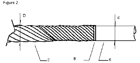
  • YANG, LINGLONG (China)
(73) Owners :
  • BEKAERT ADVANCED CORDS AALTER NV
(71) Applicants :
  • BEKAERT ADVANCED CORDS AALTER NV (Belgium)
(74) Agent: KIRBY EADES GALE BAKER
(74) Associate agent:
(45) Issued:
(86) PCT Filing Date: 2012-11-23
(87) Open to Public Inspection: 2013-06-06
Availability of licence: N/A
Dedicated to the Public: N/A
(25) Language of filing: English

Patent Cooperation Treaty (PCT): Yes
(86) PCT Filing Number: PCT/EP2012/073460
(87) International Publication Number: WO 2013079404
(85) National Entry: 2014-04-25

(30) Application Priority Data:
Application No. Country/Territory Date
PCT/CN2011/083051 (China) 2011-11-28

Abstracts

English Abstract

A steel cord (2) for an extrusion process, where a steel wire (6) is connected to the leading end of the steel cord (2). The steel wire (6) is easy to insert through an extruder head (12) and leads the steel cord (2) through the extruder head (12), to facilitate the change-over of steel cord (12) on an extruder (10) to reduce the change-over time. Also an apparatus (10), a change-over process, and the use of the steel cord (2) for an extrusion process is disclosed.


French Abstract

L'invention concerne un câble métallique (2) pour un procédé d'extrusion, un fil de fer (6) étant relié à l'extrémité avant du câble métallique (2). Le fil de fer (6) s'introduit facilement dans une tête d'extrusion (12) et conduit le cable métallique (2) à travers la tête d'extrusion (12), pour faciliter le changement du câble métallique (12) sur un extrudeur (10) afin de réduire le temps de changement. L'invention concerne également un appareil (10), un procédé de changement et l'utilisation d'un câble métallique (2) pour un procédé d'extrusion.

Claims

Note: Claims are shown in the official language in which they were submitted.

6
Claims
1. A steel cord, characterized in that a steel wire is connected to the
leading end
of said steel cord.
2. A steel cord according to claim 1, wherein the steel wire is welded to the
leading end of said steel cord.
3. A steel cord according to claim 1, wherein the diameter of the steel wire
is not
greater than the diameter of the steel cord.
4. A steel cord according to claim 3, wherein the diameter of the steel wire
is
between 60% to 100% of the diameter of the steel cord.
5. A steel cord according to claim 4, wherein the diameter of the steel wire
is
between 90% to 98% of the diameter of the steel cord.
6. A steel cord according to claim 1, wherein the surface of the steel wire is
harder than zinc.
7. A steel cord according to claim 6, wherein the steel wire is a stainless
steel
wire.
8. A steel cord according to claim 6, wherein the steel wire is coated with a
coating harder than zinc.
9. A steel cord according to claim 8, wherein the coating is a copper coating,
a
brass-coating, a nickel coating, or a chromium coating.
10. A steel cord according to claim 1, wherein the leading end of the steel
wire is
chamfered or rounded.
11. An assembly of a steel cord according to claim 1 and an extruder, said
extruder having an extruder head, wherein the length of the steel wire is
greater than the length of extruder head.
12. A process of change steel cord on an extruder, characterized by following
steps:
a. stop the extruder and remove remaining steel cords;
b. insert the steel wire of the steel cord according to claim 1 through the
extruder
head;
c. pull the steel wire and lead the steel cord through the extruder head;
d. cut off the steel wire;
e. start the extruder and resume production.
13. Use of a steel cord as claimed above for extrusion process.

Description

Note: Descriptions are shown in the official language in which they were submitted.


CA 02853644 2014-04-25
WO 2013/079404 PCT/EP2012/073460
1
STEEL CORD FOR EXTRUSION PROCESS, AN APPARATUS AND METHOD
AND USE OF SAID STEEL CORD
Description
Technical Field
[1] The invention relates to a steel cord for extrusion process, and in
particular to a steel cord where a steel wire is connected to the leading
end of the steel cord. This invention also provides an apparatus, a
change-over process, and the use of steel cord incorporating present
invention.
Background Art
[2] Elevator rope as disclosed in W02004/076327A1, and cable as disclosed
in W003/044267A1 are widely used, wherein a steel cord is coated with a
polymer material through extrusion process, as disclosed in 6E1006346.
In the extrusion process, the change over time for re-load new steel cord
is too long, because new steel cord cannot go through the extruder head
when the extruder head is full of polymer, while the polymer will burn
inside the extruder head when the heating is not turn off during change
over. Therefore, the change-over may comprise following step: stop the
extruder, turn off the heating, cool the extruder head, remove the extruder
head, open the extruder head and remove the remaining polymer inside,
reload the extruder head, insert new steel cord through the extruder head,
turn on the heating, start the extruder, fine tune the process parameter to
resume production. Since there may be 2 to 140 and more steel cords for
the extrusion process, the change-over of steel cord on an extruder is long.
In a typical application, where 12 steel cords are to be coated with polymer
simultaneously, the change-over time is around 8 hours because the
extruder head needs to be re-heated to about 500 C in an oven to remove
the PU remained inside. Therefore, industry is looking for solutions to cut
the change-over time and boost the productivity.
Disclosure of Invention
[3] The primary object of the invention is to provide a steel cord to
facilitate
the change ¨over of extrusion process. It is also the objective of present

CA 02853644 2014-04-25
WO 2013/079404 PCT/EP2012/073460
2
invention to provide the use of the steel cord for abovementioned
extrusion process.
[4] According a first aspect of the invention a product is claimed that a
steel
cord is characterized in that a steel wire is connected to the leading end of
said steel cord, wherein the leading end means the end of steel cord
which is on the surface of steel cord spool.
[5] The inventive product relates to the combination of features as
described
in claim 1. Specific features for preferred embodiments of the invention are
set on in the dependent claims.
[6] According to present invention, the steel wire is welded to the leading
end
of said steel cord. Besides, other ways of connection can be brazing,
soldering, and gluing.
[7] According to present invention, the diameter of the steel wire is not
greater
than the diameter of the steel cord. Preferably the diameter of the steel
wire is between 60% to 100% of the diameter of the steel cord, and more
preferably the diameter of the steel wire is between 90% to 98% of the
diameter of the steel cord.
[8] According to present invention, the surface of the steel wire is harder
than
zinc, and preferably the steel wire is either a stainless steel wire or a
steel
wire coated with a coating harder than zinc, wherein the coating can be a
copper coating, a brass-coating, a nickel coating, or a chromium coating.
[9] According to present invention, the leading end of the steel wire is
chamfered or rounded to facilitate the insertion of steel wire through the
extruder head.
[10] According a second aspect of the invention an apparatus is claimed
that
an assembly of steel cord according to claim 1 and an extruder having an
extruder head, wherein the length of the steel wire is greater than the
length of extruder head.
[11] According a third aspect of the invention a process is claimed that a
process for change steel cord on an extruder is characterized by following
steps:
[12] a. stop the extruder and remove remaining steel cords
[13] b. insert the steel wire of the steel cord according to claim 1
through the
extruder head;

CA 02853644 2014-04-25
WO 2013/079404
PCT/EP2012/073460
3
[14] c. pull the steel wire and lead the steel cord through the extruder
head;
[15] d. cut off the steel wire;
[16] e. start the extruder and resume production.
[17] According a fourth aspect of the invention a method is claimed that
the
use of a steel cord as claimed in claim 1 for extrusion process.
Brief Description of Figures in the Drawings
[18] Figure 1 describes a first preferred embodiment of the invention.
[19] Figure 2 describes a magnified view of first preferred embodiment.
[20] Figure 3 describes an apparatus of the invention.
Mode(s) for Carrying Out the Invention
[21] Preferred embodiments of the present invention will be described
herein
below with reference to the accompanying figures.
[22] A first embodiment is illustrated in Figure 1, wherein a steel cord 2
is
wound on a steel cord spool 4, and a steel wire 6 is connected to the
leading end 8 of the steel cord 2.
[23] The steel wire 6 can be welded to the leading end 8 of the steel cord
2 as
disclosed in W02003/100164A1, while other ways of connection can be
brazing, soldering, and gluing as disclosed in W02004/007833A1. Since
leading steel cord through extruder head may needs a few hundred
newton, welding and other ways of connections will do. Compared with
other ways of connection, welding is a very good option, because in the
extrusion process the connection will go through the extruder head which
is heated at a temperature as high as 230 C and the connection between
the steel cord and steel wire can be maintained.
[24] Figure 2 illustrates a magnified view of the connection between steel
cord
2 and steel wire 6, wherein D is the diameter of the steel cord 2 and d the
diameter of the steel wire 6. The diameter of the steel wire 6 is not greater
than the diameter of the steel cord 2, because in the extrusion process the
gap between the steel cord and the inner surface of the extruder head is
usually about 0.05mm to 0.5mm, and it is better to have a leading wire
with smaller diameter to guide the steel cord through the extruder head.
The diameter of the steel wire is preferred between 60% to 100%, and
more preferred between 90% to 98%, of the diameter of the steel cord,

CA 02853644 2014-04-25
WO 2013/079404
PCT/EP2012/073460
4
because we need more area between the steel cord 2 and steel wire 6 to
maintain a strong connection.
[25] A mechanical test on a specimen shows following data
Steel cord diameter 1.61mm
Steel wire diameter 1.56mm
Steel wire diameter / steel cord diameter 97%
Steel cord break load 3000N
Weld connection break load 1311N
Weld connection break load / steel cord break load 44%
[26] While the According to present invention, the surface of the steel
wire is
harder than zinc, and preferably the steel wire is either a stainless steel
wire or a steel wire coated with a coating harder than zinc, wherein the
coating can be a copper coating, a brass-coating, a nickel coating, or a
chromium coating.
[27] Firstly, the surface of the steel wire is harder than zinc, because
the steel
wire is to be inserted through the extruder head and the hard surface of
the steel wire is to guarantee that the steel wire is not to be cut and jam
inside the extruder head. Secondly, a stainless steel wire is a good option,
because not only stainless steel wire itself is strong enough but also the
surface of stainless steel wire is hard enough to go through the extruder
head. Thirdly, a steel wire coated with a coating harder than zinc, for
example, a copper coating, a brass-coating, a nickel coating, or a
chromium coating, is also a good option, because not only steel wire itself
is strong enough but also the surface of the coated steel wire is hard
enough to go through the extruder head.
zo [28] According to present invention, the leading end of the steel
wire is
chamfered or rounded to facilitate the insertion of steel wire through the
extruder head.
[29] Figure 3 illustrates an apparatus 10 of present invention, wherein
steel
wire 6, connected to the leading end of steel cord 2, is inserted through an
extruder head 12. L the length of the steel wire 6 is greater than H the
length of the extruder head 12, because steel wire should be longer than
the extruder head to insert through.

CA 02853644 2014-04-25
WO 2013/079404
PCT/EP2012/073460
[30] The process for change steel cord incorporating present invention on
an
extruder is characterized by following steps:
[31] a. stop the extruder and remove remaining steel cords;
[32] b. insert the steel wire of the steel cord according to claim 1
through the
5 extruder head;
[33] c. pull the steel wire and lead the steel cord through the extruder
head;
[34] d. cut off the steel wire;
[35] e. start the extruder and resume production.
[36] Since the steel wire is strong and can be easily inserted through the
extruder head, it is not necessary to stop the heating of the extruder,
because the changeover of steel cord can be done in a minute.
[37] The use of the steel cord incorporating present invention for
extrusion
process.

Representative Drawing
A single figure which represents the drawing illustrating the invention.
Administrative Status

2024-08-01:As part of the Next Generation Patents (NGP) transition, the Canadian Patents Database (CPD) now contains a more detailed Event History, which replicates the Event Log of our new back-office solution.

Please note that "Inactive:" events refers to events no longer in use in our new back-office solution.

For a clearer understanding of the status of the application/patent presented on this page, the site Disclaimer , as well as the definitions for Patent , Event History , Maintenance Fee  and Payment History  should be consulted.

Event History

Description Date
Inactive: IPC deactivated 2021-10-09
Inactive: First IPC assigned 2019-11-07
Inactive: IPC assigned 2019-11-07
Inactive: IPC expired 2019-01-01
Time Limit for Reversal Expired 2018-11-23
Application Not Reinstated by Deadline 2018-11-23
Deemed Abandoned - Failure to Respond to Maintenance Fee Notice 2017-11-23
Inactive: Abandon-RFE+Late fee unpaid-Correspondence sent 2017-11-23
Letter Sent 2016-06-08
Inactive: Single transfer 2016-06-02
Inactive: Cover page published 2014-06-30
Inactive: Correspondence - PCT 2014-06-20
Inactive: Inventor deleted 2014-06-11
Inactive: IPC assigned 2014-06-11
Inactive: First IPC assigned 2014-06-11
Inactive: Notice - National entry - No RFE 2014-06-11
Application Received - PCT 2014-06-11
National Entry Requirements Determined Compliant 2014-04-25
Application Published (Open to Public Inspection) 2013-06-06

Abandonment History

Abandonment Date Reason Reinstatement Date
2017-11-23

Maintenance Fee

The last payment was received on 2016-10-24

Note : If the full payment has not been received on or before the date indicated, a further fee may be required which may be one of the following

  • the reinstatement fee;
  • the late payment fee; or
  • additional fee to reverse deemed expiry.

Please refer to the CIPO Patent Fees web page to see all current fee amounts.

Fee History

Fee Type Anniversary Year Due Date Paid Date
Basic national fee - standard 2014-04-25
MF (application, 2nd anniv.) - standard 02 2014-11-24 2014-10-28
MF (application, 3rd anniv.) - standard 03 2015-11-23 2015-10-21
Registration of a document 2016-06-02
MF (application, 4th anniv.) - standard 04 2016-11-23 2016-10-24
Owners on Record

Note: Records showing the ownership history in alphabetical order.

Current Owners on Record
BEKAERT ADVANCED CORDS AALTER NV
Past Owners on Record
LINGLONG YANG
PENGFEI WANG
ZHICHAO CHENG
Past Owners that do not appear in the "Owners on Record" listing will appear in other documentation within the application.
Documents

To view selected files, please enter reCAPTCHA code :


To view images, click a link in the Document Description column. To download the documents, select one or more checkboxes in the first column and then click the "Download Selected in PDF format (Zip Archive)" or the "Download Selected as Single PDF" button.

List of published and non-published patent-specific documents on the CPD .

If you have any difficulty accessing content, you can call the Client Service Centre at 1-866-997-1936 or send them an e-mail at CIPO Client Service Centre.


Document
Description 
Date
(yyyy-mm-dd) 
Number of pages   Size of Image (KB) 
Description 2014-04-25 5 202
Abstract 2014-04-25 1 60
Claims 2014-04-25 1 39
Drawings 2014-04-25 1 33
Representative drawing 2014-06-12 1 6
Cover Page 2014-06-30 1 37
Notice of National Entry 2014-06-11 1 193
Reminder of maintenance fee due 2014-07-24 1 112
Courtesy - Abandonment Letter (Request for Examination) 2018-01-04 1 167
Courtesy - Abandonment Letter (Maintenance Fee) 2018-01-04 1 175
Courtesy - Certificate of registration (related document(s)) 2016-06-08 1 102
Reminder - Request for Examination 2017-07-25 1 116
PCT 2014-04-25 4 117
Correspondence 2014-06-20 6 213