Note: Descriptions are shown in the official language in which they were submitted.
WO 2013/066930 PCT/US2012/062674
METHODS AND MATERIALS FOR MODULATING START-UP TIME AND
AIR REMOVAL IN DRY SENSORS
10
Background of the Invention
1. Field of the Invention.
This invention relates to sensors useful in aqueous environments such as
glucose
sensors used in the management of diabetes.
2. Description of Related Art.
Sensors are used to monitor a wide variety of compounds in different aqueous
environments, including in vivo analytes. The quantitative determination of
analytes in
body fluids is of great importance in the diagnoses and maintenance of a
number of
pathological conditions. Illustrative analytes that are commonly monitored in
a large
number of individuals include glucose, lactate, cholesterol, and bilirubin.
The
determination of glucose concentrations in body fluids is of particular
importance to
diabetic individuals, individuals who must frequently check glucose levels in
their body
fluids to regulate the glucose intake in their diets. The results of such
tests can be crucial
in determining what, if any, insulin and/or other medication needs to be
administered.
Analyte sensors typically include components that convert interactions with
analytes into detectable signals that can be correlated with the
concentrations of the
analyte. For example, some glucose sensors use competitive binding assays, the
readout
of which is a detectable optical signal. These assays can include components
such as
glucose binding molecules coupled to elements (e.g. fluorophores) that
generate different
optical signals in the presence of glucose. Other glucose sensors use
amperometric
1
CA 2853665 2019-02-12
CA 02853665 2014-04-25
WO 2013/066930 PCT/US2012/062674
means to monitor glucose in vivo. Such amperometric glucose sensors typically
incorporate electrodes coated with the glucose oxidase, an enzyme that
catalyzes the
reaction between glucose and oxygen to yield gluconic acid and hydrogen
peroxide
(H202). The H202 formed in this reaction then alters electrode current to form
a
detectable signal.
A number of sensors designed for use in aqueous environments are placed into a
dry form following their manufacture in order to, for example, facilitate
sensor
sterilization and/or sensor packaging and/or sensor storage. In this context,
methods
and materials that facilitate the hydration of such dry sensors in aqueous
environments,
as well as other characteristics associated with sensor function in such
environments, are
desirable.
Summary of the Invention
Embodiments of the invention provide sensor systems that include compositions
disposed in specific regions of sensor architectures in order to provide
sensors with
enhanced functional and/or material properties, for example faster start-up
times.
Embodiments of the invention further provide methods for making and using such
sensor systems. While typical embodiments of the invention pertain to glucose
sensors,
the systems, methods and materials disclosed herein can be adapted for use
with a wide
variety of sensors known in the art.
The invention disclosed herein has a number of embodiments. A typical
embodiment of the invention is a sensor system comprising a sensor having an
exterior
surface and an internal matrix comprising at least one sensing complex adapted
to sense
analytes within aqueous environments. The sensor is substantially free of
water prior to
use, and includes a hygroscopic composition disposed on one or more parts of
the
sensor in order to effect certain functional characteristics. In particular,
the hygroscopic
composition is coupled to one or more regions of the sensor so as to modulate
(e.g.
increase) the rate of hydration of the sensing complex when the sensor is
disposed within
an aqueous environment. In this way, embodiments of the invention exhibit
functional
profiles (e.g. quicker start-up times) that are highly desirable to those
using such systems
2
CA 02853665 2014-04-25
WO 2013/066930 PCT/US2012/062674
(e.g. diabetic patients monitoring their physiological glucose
concentrations). For
example, in certain embodiments of the invention disclosed herein, the period
of time
between sensor contact with the aqueous environment (e.g. implantation in
vivo) and
generation of an observable analyte signal is less than 4, 3, 2 or 1 hours.
A number of aqueous analyte sensors are placed into a dry format in order to,
for
example, facilitate sensor sterilization and storage (e.g. in situations where
a sensor is
stored within a sealed, dry and sterile package environment). Processes
involving the
manufacture, packaging and storage of such sensors can result in the presence
of air
within the sensor, a phenomena that can, for example, increase the amount of
time that
the sensor must be disposed in an aqueous environment before the sensor is
able to
generate an observable analyte signal (e.g. one indicative of a concentration
of blood
glucose). In this context, certain embodiments of the invention comprise
compositions
designed to force air out of the sensors. In an illustrative embodiment of one
such
sensor system, the sensor includes a gas evolving composition coupled to one
or more
regions of the sensor and adapted to generate a gas (typically carbon dioxide)
upon
exposure to water (e.g. when the sensor is disposed within the aqueous
environment) and
in this way, displace the air so that it is forced out of the sensor. In
certain embodiments
of the invention disclosed herein, 90% of the air is forced out of the sensor
in less than
4, 3, 2 or 1 hours following sensor exposure to an aqueous environment.
Typically the sensor system embodiments adapted to include a gas evolving
composition also include a composition adapted to sequester, remove, solvate
etc., the
gas generated by the gas evolving composition. In an illustrative embodiment,
the gas
generated is carbon dioxide and the sensor system includes a carbonic
anhydrase (CA)
composition coupled to one or more regions of the sensor. In such embodiments,
the
carbonic anhydrase converts the carbon dioxide gas into soluble bicarbonates
and
protons that subsequently diffuse out of the sensor and into the aqueous
environment.
As discussed in detail below, the sensor systems of embodiments of the
invention can
include a number of other compositions, for example, those which can modulate
sensor
characteristics including those discussed above such as hydration, gas
generation and/or
gas removal. In some embodiments of the invention, the sensor comprises an
acidic
3
CA 02853665 2014-04-25
WO 2013/066930 PCT/US2012/062674
composition or a basic composition coupled to one or more regions of the
sensor and
adapted to modulate the pH within the sensor when the sensor is disposed
within the
aqueous environment. In some embodiments of the invention, the sensor
comprises a
convection composition coupled to one or more regions of the sensor and
adapted to
generate convection within the sensor when the sensor is disposed within the
aqueous
environment.
The compositions used in embodiments of the invention exhibit a surprising
degree of flexibility and versatility, characteristics which allow them to be
adapted for use
a wide variety of sensor structures. Optionally the sensor comprises a
cylindrical
structure in the form of a tubular capsule formed from a biocompatible polymer
and
having a diameter of less than 1 mm, less than 0.5 mm or less than 0.25 mm. In
some
embodiments of the invention, the internal matrix of a cylindrical sensor
comprises one
or more cavities, for example an encapsulated longitudinal cavity. In
certain
embodiments of the invention, the sensing complex, the hygroscopic
composition, the
gas evolving composition, the composition adapted to sequester, remove,
solvate etc., the
gas generated by the gas evolving composition, the convection composition
and/or the
pH modulating composition is disposed in the one or more of these cavities.
In other embodiments of the invention, the sensor structure comprises planar
layered elements and, for example, comprises a conductive layer including an
electrode,
an analyte sensing layer disposed over the conductive layer (e.g. one
comprising glucose
oxidase), and an analyte modulating layer disposed over the analyte sensing
layer. In
some embodiments of the invention, the hygroscopic composition is disposed
within a
planar layer (e.g. entrapped within a polymer of the layer), for example in
the analyte
sensing layer or the analyte modulating layer. In certain embodiments of the
invention,
the sensor electrode is disposed within a housing (e.g. a lumen of a catheter)
and the
hygroscopic composition coats a region of the housing. In one illustrative
embodiment
of the invention, the hygroscopic composition is entrapped within a
composition
disposed on an inner wall of a catheter lumen.
In many embodiments of the invention, the sensors comprise a biocompatible
region adapted to be implanted in vivo. In some embodiments, an external
sensor
4
CA 02853665 2014-04-25
WO 2013/066930 PCT/US2012/062674
structure is formed from one or more biocompatiblc polymers (e.g. those that
allow thc
diffusion of glucose thcrethrough) and is adapted to be completely implanted
in vivo. In
other embodiments, the sensor comprises a discreet probe that pierces an in
vivo
environment while other portions of the sensor remain in the external
environment. In
embodiments of the invention, the biocompatible region can comprise a polymer
that
contacts an in vivo tissue. Optionally, the polymer is a hydrophilic polymer
(e.g. one that
absorbs water). In this way, sensors used in the systems of the invention can
be used to
sense a wide variety of analytes in different aqueous environments. In common
embodiments of the invention, the sensing complex is adapted to sense glucose.
A related embodiment of the invention is a method for modulating the time
period between placement of a sensor within an aqueous environment and
generation of
a sensor signal that can be correlated with the concentration of a sensed
analyte. The
method comprises selecting the sensor to have an exterior surface and an
internal matrix
comprising at least one sensing complex adapted to sense analytes within
aqueous
environments; and a hygroscopic composition coupled to one or more regions of
the
sensor so as to modulate the rate of hydration of the sensing complex when the
sensor is
disposed within the aqueous environment (e.g. to increase the rate of
hydration as
compared to a control sensor that lacks the hygroscopic composition). This
method
further comprises placing the sensor into an aqueous environment where the
hygroscopic composition influences hydration of the sensing complex. In such
methods,
the use and positional placement of the hygroscopic composition(s) within the
sensors
can be used to modulate the time period between: (1) sensor placement in the
aqueous
environment; and (2) generation of a sensor signal that can be correlated with
the
concentration of the analyte.
Certain methodological embodiments of the invention comprise forcing air out
the internal matrix of a sensor (e.g. a cavity, such as one comprising the
sensing
complex), for example, by using a sensor that is formed to comprise a gas
evolving
composition coupled to one or more regions of the sensor, wherein the gas
evolving
composition is adapted to form carbon dioxide when the sensor is disposed
within the
aqueous environment, thereby forcing air out of the internal matrix of the
sensor.
5
CA 02853665 2014-04-25
WO 2013/066930 PCT/US2012/062674
Typically these methods include removing carbon dioxide atoms generated when
the
sensor is disposed within the aqueous environment, for example, by using a
sensor that is
formed to comprise carbonic anhydrasc, allowing the carbonic anhydrasc to
convert the
carbon dioxide into soluble bicarbonates and protons, and then allowing these
molecules
to diffuse out of the sensor into the aqueous environment. Some methodological
embodiments of the invention comprise selecting and using sensors comprising
compositions that provide other functional properties. For
example, in some
embodiments, the method comprises generating convection within the internal
matrix of
the sensor by using a sensor that is formed to comprise a convection
composition,
wherein the convection composition is coupled to one or more regions of the
sensor so
as to generate convection within the sensor (e.g. so as to facilitate mixing
of other sensor
constituents).
Optionally, the convection composition comprises a hygroscopic
composition. In addition, in some embodiments, the method comprises modulating
a
pH of a sensor region by using a sensor that is formed to include compositions
that
modulate pH in aqueous environments (e.g. buffering compounds, acid and basic
compounds and the like).
Methodological embodiments of the invention can be used with sensors having a
variety of configurations and/or sensing complexes. In
certain methodological
embodiments of the invention, the sensor comprises a cylindrical polymeric
material
having a diameter of less than 1 mm, less than 0.5 mm or less than 0.25 mm,
the internal
matrix comprises an encapsulated longitudinal cavity, and the sensing complex
comprises
a carbohydrate binding lectin (e.g. mannose binding lectin which binds
glucose) coupled
to one or more fluorophores. In other methodological embodiments of the
invention,
the sensor comprises an electrode coated with glucose oxidase and a glucose
limiting
membrane disposed over the glucose oxidase, wherein the glucose limiting
membrane
modulates the diffusion of glucose therethrough. In addition, methods of the
invention
can be performed in a variety of environments under conditions selected to be
appropriate for a particular environment. For example, in certain embodiments
of the
invention, the aqueous environment comprises an in vivo tissue and the method
is
performed at a temperature between 36 and 38 degrees centigrade (e.g. human
body
6
CA 02853665 2014-04-25
WO 2013/066930 PCT/US2012/062674
temperature).
Embodiments of the invention also provide articles of manufacture and kits for
observing a concentration of an analytc. In an illustrative embodiment, the
kit includes a
sensor comprising an exterior surface and an internal matrix comprising at
least one
sensing complex adapted to sense analytcs within aqueous environments and one
or
more hygroscopic compositions. In illustrative embodiments of the invention,
the
hygroscopic composition can comprise a saccharide compound (e.g., a
monosaccharidc,
an oligosaccharide etc.) and/or a polyol such as a polyvinyl alcohol or a
polyethylene
glycol, and/or a salt (e.g. one or more salts commonly used in pharmaceutical
compositions). Optionally the sensor includes one or more gas (e.g. carbon
dioxide)
evolving compositions in combination with one or more gas removing
compositions. In
illustrative embodiments of the invention, the gas evolving composition
comprises a
compound selected from the group consisting of NaHCO3, Na2CO3, NH4HCO3,
(NH4)2CO3, KHCO3 and K2CO3, and a carbon dioxide gas removing composition
comprises a composition selected from the group consisting of carbonic
anhydrase and
carbonic anhydrase analogues. In some embodiments, the sensing complex
comprises a
carbohydrate binding lectin coupled to a fluorophore. Alternatively, the
sensing complex
comprises an electrode coated with a glucose oxidase composition. In some
embodiments, the sensors are disposed in the kit within a sealed, sterile, dry
package that
is impermeable to CO2.
Other objects, features and advantages of the present invention will become
apparent to those skilled in the art from the following detailed description.
It is to be
understood, however, that the detailed description and specific examples,
while indicating
some embodiments of the present invention are given by way of illustration and
not
limitation. Many changes and modifications within the scope of the present
invention
may be made without departing from the spirit thereof, and the invention
includes all
such modifications.
Brief Description of the Figures
Figure 1A shows a sensor design comprising a tubular capsule that is implanted
under the skin and provides optical sensor in response to analyte (glucose).
Figure 1B
7
CA 02853665 2014-04-25
WO 2013/066930 PCT/US2012/062674
shows a view of this capsule. Figure 1C shows the relative sizc of this
capsule. Figure
1D shows a diagram of shows an alternative sensor design, one comprising an
amperometric analyte sensor formed from a plurality of planar layered
elements.
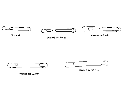
Figure 2A provide a series of photographs taken over time of two freeze dried
tubular capsule sensors that were immersed into Tris buffer (50 mM) at room
temperature. As shown in these photographs, hygroscopic, CO2 gas evolving and
CO2
gas solvating compositions can be used to modulate hydration as well as
eliminate air
from sensors immersed in an aqueous environment. The two sensors in these
photographs are: Top sensor: sensors designated "S279" and formed from a
cylindrical
polymeric material having longitudinal cavity in which the compositions are
disposed, in
addition to a sensing complex. In particular, the top sensor comprises a
cavity that
includes a glucose sensing complex and 0.2 M NaHCO. The bottom sensor: is a
S297
sensor comprising a glucose sensing complex as well as CA, 0.2 M NH4HCO3, 0.5M
Sucrose and 0.5M Galactose. Figure 2B provides a series of photographs taken
over
time of a freeze dried tubular capsule sensor having a selected combination of
hygroscopic, CO2 generating and CO2 solvating compositions (see, e.g. Table 1
below)
that has been immersed in aqueous environments.
Figure 3A provides a graph of data illustrating the startup of a freeze dried
tubular capsule sensors lacking hygroscopic compounds in an in vitro setup.
The top
curves show the response from three wet sensors and three dry sensors. As seen
the
sensor startup of the dry sensors is much longer than the already filled wet
sensors. The
startup time of the dry sensors is found to be approximately 36 hours. Figure
3B
provides a graph of data showing the startup of a freeze dried tubular capsule
sensors
comprising hygroscopic compound in an in vitro setup. The curves show the
response
from three dry sensors. As seen the sensor startup of the dry sensors is
reduced to
approximately 4 hours simply by adding two disaccharides to the composition of
the
sensor. Figures 3C-3E provides graphs of data showing how specific
combinations of
different compositions can be used to modulate sensor startup times.
Figure 4 provides a table of data which illustrates to artisans how various
combinations of the compositions disclosed herein (as well as conditions such
as
8
CA 02853665 2014-04-25
WO 2013/066930 PCT/US2012/062674
pressure) can be used to control the time required to fill a cavity/void space
(e.g. one
comprising a sensing complex) within a tubular capsule sensors. Combinations
of
compositions that fill this space in a relatively short period of time (and
which therefore
are useful in contexts where fast sensor start-up is desired) are circled.
Figure 5 provides a diagram of amperometric sensor systems having various
configurations. As illustrated by this figure, in certain embodiments of the
invention, the
sensor is disposed within tubular housing (e.g. a lumen of a catheter). In
some
embodiments of the invention, the hygroscopic composition coats a region of
this
housing. The rectangles observed through these apertures are working,
reference and
counter electrodes. In some embodiments of the invention, the hygroscopic
composition is disposed in a layer of material coated over an electrode.
Detailed Description of the Embodiments
Unless otherwise defined, all terms of art, notations and other scientific
terms or
terminology used herein are intended to have the meanings commonly understood
by
those of skill in the art to which this invention pertains. In some cases,
terms with
commonly understood meanings are defined herein for clarity and/or for ready
reference, and the inclusion of such definitions herein should not necessarily
be
construed to represent a substantial difference over what is generally
understood in the
art. Many of the techniques and procedures described or referenced herein are
well
understood and commonly employed using conventional methodology by those
skilled in
the art. As appropriate, procedures involving the use of commercially
available kits and
reagents are generally carried out in accordance with manufacturer defined
protocols
and/or parameters unless otherwise noted. A number of terms are defined below.
The term "analyte" as used herein is a broad term and is used in its ordinary
sense, including, without limitation, to refer to a substance or chemical
constituent in a
fluid such as a biological fluid (for example, blood, interstitial fluid,
cerebral spinal fluid,
lymph fluid or urine) that can be analyzed. Analytes can include naturally
occurring
substances, artificial substances, metabolites, and/or reaction products. In
common
embodiments, the analyte is glucose. However, embodiments of the invention can
be
9
CA 02853665 2014-04-25
WO 2013/066930 PCT/US2012/062674
used with sensors designed for detecting a wide variety other analytcs.
Illustrative
analytes include but are not limited to, lactate as well as salts, sugars,
proteins fats,
vitamins and hormones that naturally occur in vivo (e.g. in blood or
interstitial fluids).
The analyte can be naturally present in the biological fluid or endogenous;
for example, a
metabolic product, a hormone, an antigen, an antibody, and the like.
Alternatively, the
analyte can be introduced into the body or exogenous, for example, a contrast
agent for
imaging, a radioisotope, a chemical agent, a fluorocarbon-based synthetic
blood, or a
drug or pharmaceutical composition, including but not limited to insulin. The
metabolic
products of drugs and pharmaceutical compositions are also contemplated
analytcs.
The term "sensor" for example in "analyte sensor," is used in its ordinary
sense,
including, without limitation, means used to detect a compound such as an
analyte. A
"sensor system" includes, for example, elements, structures and architectures
(e.g.
specific 3-dimensional constellations of elements) designed to facilitate
sensor use and
function. Sensor systems can include, for example, compositions such as those
having
selected material properties, as well as electronic components such as
elements and
devices used in signal detection (e.g. optical detectors, current detectors,
monitors,
processors and the like). The term "sensing complex" as used herein refers to
the
elements of a sensor that interact with and generate a signal indicative of, a
particular
analyte (e.g. glucose and the like). The term "matrix" is used herein
according to its art-
accepted meaning of something within or from which something else is found,
develops,
and/or takes form.
As discussed in detail below, typical embodiments of the invention relate to
the
use of a sensor that measures a concentration of an aqueous analyte of
interest or a
substance indicative of the concentration or presence of the analyte in vivo.
In some
embodiments, the sensor is a subcutaneous, intramuscular, intraperitoneal,
intravascular
or transdermal device (e.g. is in the form of a capsule and/or fiber).
Typically the sensor
can be used for continuous analyte monitoring. In some embodiments, the device
can
analyze a plurality of intermittent blood samples. The sensor embodiments
disclosed
herein can use any known method, including invasive, minimally invasive, and
non-
invasive sensing techniques, to provide an output signal indicative of the
concentration
WO 2013/066930 PCT/US2012/062674
of the analyte of interest.
Embodiments of the invention disclosed herein provide sensors designed to
include compositions disposed in specific areas of the sensor in order to
provide the
sensors with enhanced functional and/or material properties. The disclosure
further
provides methods for making and using such sensors. Embodiments of the
invention
described herein can be adapted and implemented with a wide variety of known
sensors.
Such sensors include, for example, those having sensing complexes that
generate an
optical signal that can be correlated with the concentration of an analyte
such as glucose.
A number of these sensors are disclosed, for example in U.S. Patent
Application
Publication Nos. 20080188723, 20090221891, 20090187084 and 20090131773.
Embodiments of the
invention described herein can also be adapted and implemented with
amperometric
sensor structures, for example those disclosed in U.S. Patent Application
Publication
Nos. 20070227907, 20100025238, 20110319734 and 20110152654,
A number of aqueous analyte sensors are placed into a dry format in order to,
for
example, facilitate sensor sterili7ation and storage (e.g. in situations where
a sensor is
stored within a sealed, dry and sterile package environment). In addition to
being dry,
processes involving the manufacture, packaging and storage of such sensors can
result in
the presence of air within the sensor, a phenomena that can, for example,
increase the
amount of time that the sensor must be disposed in an aqueous environment
before the
sensor is able to generate an observable analyte signal (e.g. one indicative
of a
concentration of blood glucose). The air inside certain sensor designs can
take days to
remove if the sensor is simply immersed into a buffer of the same osmotic
pressure as a
buffer inside the sensor.
Certain conditions can be applied to such sensors to facilitate air removal by
increasing a rate of hydration and/or gas solubility and/or the dissolution of
entrapped
gases (e.g. air). Conditions include lowered temperatures, which are known to
increase
the gas solubility in general, as well as increased pressures (increased
pressures increase
gas solubility a characterized by according to Henry's law). However, the
manipulation
11
CA 2 853 6 65 2 02 0-0 1-2 4
CA 02853665 2014-04-25
WO 2013/066930 PCT/US2012/062674
of these conditions is not always compatible with sensor use in certain
contexts, for
example in certain uses in vivo. For example with in vivo sensors (e.g.
glucose sensors), a
desirable start-up time would entail air removal within an hour or less,
without cooling
the sensor or pressurizing the sensor during the startup procedure. In
addition, in certain
contexts, it is desirable that dry sensors be used, as compared, for example
to semi-filled
wet sensors. Unfortunately, the dry state places even larger demands on
solutions into
which a sensor is placed. It is highly desirable to be able to both wet a
sensor, and while
wetting, remove air from inside the sensor. In many desirable contexts, such
processes
should be able to occur inside the body of a patient i.e. at relatively high
temperatures.
The invention disclosed herein is designed to meet such challenges and the
instant disclosure provides a number of working embodiments for doing so. A
typical
embodiment of the invention is a sensor system comprising a sensor having an
exterior
surface and an internal matrix comprising at least one sensing complex adapted
to sense
analytes within aqueous environments. The sensor in this system is
substantially free of
water prior to use, and includes compositions disposed on one or more parts of
the
sensor in order to effect certain desirable functional characteristics.
In certain embodiments of the invention, one or more hygroscopic compositions
can be coupled to one or more regions of a sensor so as to modulate (e.g.
increase) the
rate of hydration of the sensing complex when the sensor is disposed within an
aqueous
environment. The term "coupled' as used in this context, means localization of
the
composition to a defined area (e.g. one comprising a sensing complex), either
temporarily, or permanently. Compositions can be coupled to a defined area in
a variety
of ways. Illustrative, but non limiting ways in which a composition can be
coupled to an
area include, for example, disposing a composition within an enclosed void or
cavity (see,
e.g. the working example) and/or otherwise disposing a composition within a
material
(e.g. within a polymer matrix) and/or coating a surface of a material with a
composition
etc.
As used herein, "hygroscopic compositions" comprise those materials that can
draw water into an area. As disclosed herein, the wetting of sensors can be
greatly
enhanced by formulating the sensor using hygroscopic compositions. A wide
variety of
12
CA 02853665 2014-04-25
WO 2013/066930 PCT/US2012/062674
hygroscopic compositions are known in the art which can be adapted for use
with
embodiments of the invention. The working embodiments of the sensors disclosed
herein use various salts and sugars as well as polyols such as poly vinyl
alcohol (PVA). In
certain embodiments of the invention, the hygroscopic composition comprises
combinations of monosaccharides (e.g. glucose) and disaccharides (e.g.
sucrose, lactose
and the like).
Hygroscopic compositions useful in embodiments of the invention can include,
but are not limited to, these carbohydrates including monosaccharides,
disaccharides and
polysaccharides. These include monosaccharides such as glucose, dextrose
(anhydrous
and monohydrate), galactose, mannitol, D-mannose, sorbitol, sorbose and the
like;
disaccharides such as lactose, maltose, sucrose, trehalose, and the like;
trisaccharides such
as raffinose and the like; and other carbohydrates such as starches
(hydroxyethylstarch),
cyclodextrins, maltodextrins and hyaluronic acid. Hygroscopic compositions can
also
include salts such as one or more pharmaceutically acceptable salts, for
example those
disclosed in Remington: The Science and Practice of Pharmacy, University of
the
Sciences in Philadelphia (Ed), 21st Edition (2005). In some embodiments of the
invention, a hygroscopic composition comprises a salt selected from the group
consisting
of sodium chloride, potassium chloride calcium chloride, magnesium chloride,
zinc
chloride, potassium carbonate, potassium phosphate, carnallite, ferric
ammonium citrate,
potassium hydroxide, and sodium hydroxide.
As noted above, depending upon the sensor structure and function desired,
hygroscopic compositions useful with the invention can include a wide variety
of
combinations of sugars, salts, water soluble electrolytes, small organic
compounds, and
osmotic adjusting compositions to increase the osmotic pressure within an area
and
attract water. Other examples of hygroscopic compositions include polyethylene
glycols,
microcrystalline cellulose (AVICEL PH 200, AVICEL PH 101), Ac-Di-Sol
(Croscarmelose Sodium) and PVP-XL (a crosslinked polyvinylpyrrolidone),
starches and
modified starches, polymers, and gum such as arabic and xanthan, and
hydroxyalkyl
cellulose such as hydroxymethylcellulo se,
hydroxypropylcellulos e and
hydroxyopropylmethylcellulose. Certain hygroscopic compositions of the
invention
13
CA 02853665 2014-04-25
WO 2013/066930 PCT/US2012/062674
include hydrogels (highly absorbent natural or synthetic polymers) such as
those
constructed from networks of biocompatiblc polymers, such as poly(ethylene
glycols).
As shown in Figures 2-4, hygroscopic compounds such as saccharides (e.g.
monosaccharides, disaccharides, trisaccharides, oligosaccharides and the like)
as well as
polyols (e.g. poly vinyl alcohols, mannitol, sorbitol and the like),
polyethylene glycol
(PEG) molecules of various molecular weights, as well as salts (e.g. NaC1, KC1
and the
like) can be used to greatly enhance the startup time of sensors. The data
presented in
Figures 3A and 3B shows that hygroscopic compositions can decrease the start-
up time
period for an illustrative sensor from 36 hours (i.e. the time period for a
control sensor
lacking these compositions) down to under 4 hours when the same sensor is
formulated
to comprise the hygroscopic compositions sucrose and trehalose.
The data presented in FIG. 3 shows that the addition of hygroscopic
compositions can be use to modulate (typically to increase) startup time of
the sensor.
This shows for example, that disposing such compositions at particular sensor
areas, for
example, by forming a sensor matrix (one that is ultimately dried) to include
hygroscopic
compounds within a cavity/void in which a sensing complex (e.g. one comprising
a
binding assay) is also disposed helps to increase startup time. Different
compositions
can be used with different sensors in order to modulate conditions in specific
ways. For
example in some embodiments of the invention, osmotic pressure of the
compositions
used during the wetting can be modulated by using hygroscopic compounds which
are
selected for an ability to migrate from a site at which they were originally
disposed by, for
example, diffusing away from the site following sensor placement in an aqueous
environment (e.g. by selecting low molecular weight saccharides that can
diffuse through
a polymeric matrix without being entrapped). Alternatively, hygroscopic
compounds can
be adapted or selected to remain in a specific area of a sensor for some
extended period
of time, for example by irreversibly coupling them to a fixed location, or by
using a high
molecular weight hygroscopic compounds they have difficulty diffusing through
a
polymeric matrix (e.g. polyols of selected molecular weights) and/or sugars
having
selected molecular weights etc. and, in this way, maintain an osmotic pressure
at a
location for a controlled period of time (e.g. to produce a faster startup
time). Polymers
14
WO 2013/066930
PCT/US2012/062674
useful for forming sensors of the invention include hydrogels, acrylates and
the like (see,
e.g. U.S. Patent Application Publication Nos. 20080188723, 20090221891,
20090187084
and 20090131773.
Embodiments of the invention include materials and methods for removing gases
within a sensor (i.e. air, combinations of 02 and N2 and other minor
constituents) as well
as other gases (e.g. N2, He or Ne gasses introduced into sensors and/or
packaging due to
their relatively inert nature and/or solubility profiles) from inside a wetted
polymer
structure by using osmotic forces generated by hygroscopic compositions, gas
evolution
to increase pressure and an efficient method to remove the evolved gas from
gas phase
to solvated phase at ambient pressure and body temperature. Embodiments of the
invention exhibit functional profiles (e.g. quicker start-up times) that are
highly desirable
to those using such systems (e.g. diabetic patients who play an active role in
monitoring
physiological glucose concentrations). For example, in certain embodiments of
the
invention disclosed herein, the period of time between sensor contact with the
aqueous
environment (e.g. implantation in am) and generation of an observable analyte
signal is
less than 4, 3, 2 or 1 hours.
In this context, certain embodiments of the invention comprise compositions
designed to force air out of the sensors. In an illustrative embodiment of one
such
sensor system, the sensor includes a gas evolving composition coupled to one
or more
regions of the sensor and adapted to generate a gas upon exposure to water
(e.g. when
the sensor is disposed within the aqueous environment) and in this way,
displace the air
so that it is forced out of the sensor. In certain embodiments of the
invention disclosed
herein, 90% of the air is forced out of the sensor in less than 4, 3, 2 or 1
hours following
sensor exposure to an aqueous environment. As discussed below, typical
embodiments
of the invention, a gas evolving composition produces carbon dioxide. In some
embodiments of the invention, a gas within the sensor, for example one
introduced
during manufacturing, is selected to have a relatively high solubility as
compared to gases
found in air (e.g. He, Ne and the like). In certain embodiments, one or more
gases
introduced into the sensor and/or produced by a gas evolving composition is
elected for
high solubility due to an equilibrium in water (e.g. NH3/NH4+) and/or an
ability to
CA 2853665 2019-02-12
CA 02853665 2014-04-25
WO 2013/066930 PCT/US2012/062674
form soluble compounds when exposed to an aqueous environments (optionally in
combination with acidic or basic cxcipient compositions).
A working embodiment of the invention that is disclosed herein uses
bicarbonates (hydrogen carbonates) that are capable of liberating CO2 gas
under acidic
conditions as gas evolving compositions. In this context, acidic conditions
during the
startup can be generated by adding acidic excipicnts in to the composition.
Similarly, the
presence of high concentrations of sugars or other hydroscopic compositions
also
change the activity coefficients solutions making them acidic (e.g. adding 0.5
M sucrose
to a 50 mM Tris buffer pH 7.68 changes the pH to approx. 3.5 in the resulting
solution).
In view of this, certain embodiments of the invention use high sugar
concentrations and
bicarbonates to liberate CO2 gas during wetting and hence increase the gas
pressure
inside the sensor. Optionally, a CO2 gas generating composition comprises a
compound
selected from the group consisting of NaHCO3, Na2CO3, NH4HCO3, (NH4)2CO3,
KHCO3 and K2CO3. In certain embodiments of the invention, the sensors are
sealed
within gas impermeable packaging in order to, for example, inhibit any loss of
CO2 from
such carbonates (and change the carbonate content).
After the generation of CO2 gas, the dissolution of this CO2 in to water is a
relatively slow process. Consequently, merely exchanging 02 and N2 (i.e. air)
with CO2
does not necessarily help to increase startup time. Consequently, as disclosed
herein,
certain sensor system embodiments are adapted to include a gas evolving
composition
also include a composition adapted to sequester, solvate or otherwise remove
the gas
generated by the gas evolving composition. In this context a number of
materials that
sequester gases such as CO2 are known in the art (see, e.g. Huang et al., Proc
Nati_ Acad
Sci 2011 108(4): 1222-1227). In addition, the slow process of dissolving CO2
gas in
water is in nature catalyzed by an enzyme Carbonic Anhydrase (CA) or carbonate
dehydratase (EC 4.2.1.1). The carbonic anhydrases (or carbonate dehydratases)
form a
family of enzymes that catalyze the rapid interconversion of carbon dioxide
and water to
bicarbonate and protons (or vice versa), a reversible reaction that occurs
rather slowly in
16
CA 02853665 2014-04-25
WO 2013/066930 PCT/US2012/062674
the absence of a catalyst (CO2 + H20 (-2 H2CO3). One of the functions of this
enzyme
in animals is to interconvert carbon dioxide and bicarbonate to maintain acid-
base
balance in blood and other tissues, and to help transport carbon dioxide out
of tissues.
The rate of conversion is diffusion controlled i.e. the fastest possible
reaction is obtained
by the presence of CA. CA is found in all higher organisms is all
compartments. In
laboratories the CA is commonly used to keep CO2/H2CO3 equilibrium when
working
with mammalian cell lines (in CO2 incubators). CA is readily available from
SIGMA
ALDRICH, for example as both bovine and human variants.
Formulating the sensor with CA, a disaccharide, monosaccharide and HCO3-
yields a composition that can remove air relatively quickly as compared to a
sensor
containing only the hygroscopic compounds and/or gas evolving compositions.
Results
from control experiments shown in Table 1 below confirm that a hygroscopic
composition, a gas evolving composition and CA can be use to obtain fast
startup. The
results from illustrative experiments are as follows:
TABLE 1
Composition of composition 90% air removal
0.5 M Sucrose + CA > 4 hour
0.5 M Sucrose + 0.2 M NaHCO3 > 4 hours
0.2 M NaHCO3 + CA > 10 hours
0.5 M Sucrose + 0.2 M NaHCO3
+ CA 30 minutes
As shown above, by incorporating a composition comprising 0.5 M disaccharide,
0.5 M monosaccharide and 0.2 M HCO3- and excess of CA inside of a
representative
sensor, 90% of air is removed in approximately 30 minutes. As shown in FIG. 4,
using
such information, artisans can make optimized concentrations for a variety of
sensors
and/or usc an optimized combination of compositions (such as di- and
monosaccharides) for a desired application, for example an optimal bicarbonate
17
CA 02853665 2014-04-25
WO 2013/066930 PCT/US2012/062674
concentration needed to keep the reactions proceeding at a desired rate until
all air is
removed. Ways to optimize the rate of hydration and/or the air removal in
various
sensor structures include the three dimensional placement and/or distribution
of the
compositions within a sensor structure, for example to drive fluids in a
specific direction
or generate (or solvate) gas in a specific location (e.g. towards a sensing
complex) etc. As
discussed below, depending upon the nature of the sensor in which embodiments
of the
sensor are used, additional ways to optimize the rate of hydration and/or the
air removal
in various sensor structures include, for example: (1) controlling pH during
startup in
order to optimize the gas evolution; (2) varying the concentrations of the
various
compositions; (3) selecting specific combinations of compositions, for example
combining highly soluble compounds (fast dissolution) with compounds having
lower
solubility (slower dissolution); and (4) selecting the specific site (e.g. an
internal cavity)
and manner in which such compositions are disposed within the sensor (e.g. to
make
them diffuse away from the site a specific rate or, to entrap them at that
site etc.). For
example, as is known in the art, higher concentrations of excipients can
produce higher
osmotic pressures and hence the faster the air removal. Other factors relating
to the
mechanisms of the invention can be considered as well. For example, some
embodiments of the invention are designed so that the "osmolality" of the
compositions
is in a concentration range from 2M to 4M in total including a disaccharide, a
mono
saccharide and a bicarbonate.
As noted above, in an illustrative embodiment of the invention, the gas
generated
is carbon dioxide and the sensor system includes a carbonic anhydrase
composition
coupled to one or more regions of the sensor. In such embodiments, the
carbonic
anhydrase converts the carbon dioxide gas into soluble bicarbonates and
protons that
subsequently diffuse out of the sensor and into the aqueous environment. As
disclosed
herein, the sensor systems of embodiments of the invention can include a
number of
other compositions, for example those which can modulate sensor
characteristics
including those discussed above such as hydration, gas generation and/or gas
removal.
In some embodiments of the invention, the sensor comprises a composition that
forms
an acidic excipient or a basic excipient coupled to one or more regions of the
sensor and
18
CA 02853665 2014-04-25
WO 2013/066930 PCT/US2012/062674
adapted to modulate the pH within the sensor when the sensor is disposed
within the
aqueous environment. "Acidic excipicnt" as that term is used herein refers to
any
organic acid. These cxcipients can be added as the acid, or as the salt form
of the
conjugate base of the acid. For example, the acidic excipient citric acid can
be added
either in the acid form, citric acid, or as the salt form of the conjugate
base, for example,
the mono-, di-, or trisodium salt of the citric acid. Illustrative acidic
excipicnts include
citric acid, ascorbic acid, acetic acid, ethylenediaminetctra acetic acid,
saturated fatty acids,
bile acids, dicarboxylic acids, and combinations thereof. Illustrative basic
excipients
include a number of inorganic or organic bases which are physiologically
harmless, that
is, pharmaceutically acceptable, at least in the dosage ranges used, such as
sodium
hydroxide, potassium hydroxide, ammonia, tert.-sodium phosphate,
diethanolamine,
ethylenediamine, N-methylglucamine or L-lysine.
As disclosed herein, the sensor can also include a variety of other compounds
such as surfactants (e.g. Tween-80, Triton X100 used in the working examples).
These
can be anionic, cationic, nonionic, and Zwitterionic surfactants. In some
embodiments
of the invention, the sensor comprises a colloid composition selected to
increase the
solubility of a gas generated by a gas generating composition. In certain
embodiments of
the invention, the sensor comprises a convection composition coupled to one or
more
regions of the sensor and adapted to generate convection within the sensor
when the
sensor is disposed within the aqueous environment.
As disclosed for example in Figure 4, various combinations of compositions can
be used in embodiments of this invention (e.g. those including Sucrose +
NaHCO3 +
CA), combinations which can be selected in view of the specific sensor
structures in
which they are used as well the specific functional effect that is desired for
that sensor.
With embodiments of the tubular capsule sensors that are shown in Figures 1
and 2,
where fast hydration and air removal is desired, it is observed that
embodiments work
well with combinations of monosaccharides and disaccharides when one sugar is
selected
to be highly soluble (see, e.g. Sucrose>Lactose>Trehalose and related
solubility
comparisons). In situations where sensors comprise an internal cavity that
includes a
solubilizable sensor complex, a complex/assay distributed on entire inside
surface of the
19
CA 02853665 2014-04-25
WO 2013/066930 PCT/US2012/062674
sensor cavity in order to provide selected results. Sucrose (or glucose) are
highly soluble
sugars that contribute to ensure wetting and dissolution/distribution of the
assay inside
the sensor cavity (and raise the osmotic pressure). PVAs of various molecular
weights
(c.g.6 kDa or 195 kDa etc.) can also be employed to decrease the time for air
removal.
The compositions used in embodiments of the invention exhibit a surprising
degree of flexibility and versatility, characteristics which allow them to be
adapted for use
in a wide variety of sensor structures. In this context, embodiments of the
invention can
use sensors and/or sensor elements selected to have shapes and sizes and
materials that
influence diffusion through the sensor. For example, in some embodiments of
the
invention, the sensor is designed to have a geometry that facilitates in vivo
placement and
analyte diffusion into the sensor, and is, for example spherical, ellipsoid,
tubular or the
like. In certain embodiments of an invention the size of the sensor is kept
below a
minimum size in order to facilitate the diffusion of compounds therethrough.
In some
embodiments of the invention, one or more sensor elements can comprise a
structure
formed from a polymeric composition through which water and other compounds
such
as analytes (e.g. glucose) can diffuse. Illustrative polymeric compositions
are disclosed in
U.S. Patent Publication No. 20090221891 and include, for example, material
(e.g. one
that is biodegradable) comprising a polymer having hydrophobic and hydrophilic
units.
Specific polymers can be selected depending upon a desired application. For
example,
for mobility of glucose, a material can be selected to have a molecular weight
cut-off limit
of no more than 25000 Da or no more than 10000 Da. Components disposed within
such polymeric materials (e.g. sensing complexes) can be of high molecular
weight, for
example proteins or polymers, in order to prevent their loss from the sensor
by diffusion
through the polymeric materials. In an illustrative embodiment, hydrophilic
units of a
polymeric material comprise an ester of polyethylene glycol (PEG) and a
diacid, and the
molecular weight cut-off limit is affected by the PEG chain length, the
molecular weight
of the polymer and the weight fraction of the hydrophilic units. The longer
the PEG
chains, the higher the molecular weight cut-off limit, the higher the
molecular weight of
the polymer, the lower the molecular weight cut-off limit, and the lower the
weight
fraction of the hydrophilic units, the lower the molecular weight cut-off
limit.
CA 02853665 2014-04-25
WO 2013/066930 PCT/US2012/062674
Sensor components can be selected to have properties that facilitate their
storage
and or sterilization. In some embodiments of the invention, all components of
the
sensor are selected for an ability to retain sensor function following a
sterilization
procedure (e.g. c-beam sterilization). In some embodiments of the invention,
all
components of the sensor are selected for an ability to retain sensor function
following a
drying procedure (e.g. lyophilization).
In illustrative embodiments of the invention, the sensor comprises a
cylindrical/tubular architecture and has a diameter of less than 1 mm, 0.9 mm,
0.8 mm,
0.7 mm, 0.6 mm, 0.5 mm, 0.4 mm, 0.3 mm or 0.2 mm. Illustrative sensors of this
type
are shown in FIG. 1. In certain examples, the sensor has a diameter of about
0.5 mm or
about 0.25 mm. In some embodiments, the body of sensor is formed from a
polymeric
material. Optionally, the sensor is in the form of a fiber. In some
embodiments of the
invention, the internal matrix of a cylindrical sensor comprises one or more
cavities or
voids, for example a encapsulated longitudinal cavity. In certain embodiments
of the
invention, the sensing complex, the hygroscopic composition, the gas evolving
composition, the composition adapted to sequester, remove, solvate etc., the
gas
generated by the gas evolving composition, the convection composition and/or
the pH
modulating composition is disposed in the one or more of these cavities/voids.
Optionally the sensing complex produces an optical signal that can be
correlated
with an analyte of interest, for example, glucose. A sensing complex (e.g. one
comprising
a binding assay) generating the optical signal should preferably be reversible
such that a
continuous monitoring of fluctuating levels of analyte can be achieved.
Optionally, the
detectable or measurable optical signal is generated using a proximity based
signal
generating/modulating moiety pair so that a signal is generated or modulated
when a first
member of the pair is brought into close proximity with a second member of the
pair. In
one illustrative embodiment, the analyte binding agent (e.g. a lectin such as
mannose
binding lectin as disclosed in WO 2006/061207) is labelled with one of a
proximity based
signal generating/modulating moiety pair and the analyte analogue is labelled
with the
other of the proximity based signal generating/modulating moiety pair, and
there is a
.. detectable difference in signal when the analyte analogue and analyte
binding agent form
21
WO 2013/066930 PCT/US2012/062674
the complex and when the analyte analogue is displaced by the analyte from the
complex.
Typically, the proximity based signal generating/modulating moiety pair is an
energy
donor moiety and energy acceptor moiety pair. Energy donor moieties and energy
acceptor moieties arc also referred to as donor and acceptor chromophores (or
light
absorbing materials) respectively. An energy acceptor which does not emit
fluorescence
is referred to as a quenching moiety. In such embodiments, a lectin can be
labelled with
one of an energy donor and energy acceptor moiety pair and the analyte
analogue is
labelled with the other of the energy donor and energy acceptor moiety pair.
The
detectable difference in signal corresponds to a detectable difference in
energy transfer
from the energy donor moiety to the energy acceptor moiety. Optionally, the
analyte
analogue bears the energy acceptor moiety and the analyte binding agent bears
the energy
donor moiety. In certain embodiments of the invention, the sensor of the
invention
incorporates an assay which generates an optical readout using the technique
of
fluorescence resonance energy transfer (FRET).
In one illustrative embodiment of the sensors discussed in the paragraph
above,
the variants of the competitive binding assay each comprise: an analyte
binding agent
labelled with a first light-absorbing material; a macromolecule labelled with
a second
light-absorbing material and comprising at least one analyte analogue moiety;
wherein the
analyte binding agent binds said at least one analyte analogue moiety of the
macromolecule to form a complex from which said macromolecule is displaceable
by
said analyte, and wherein said complex is able to absorb light energy and said
absorbed
light energy is able to be non-radiatively transferred between one of the
light-absorbing
materials and the other of the light-absorbing materials with a consequent
measurable
change in a fluorescence property of said light absorbing materials when
present in said
complex as compared to their said fluorescence property when said
macromolecule is
displaced by said analyte from said complex, and wherein the different
variants of the
assay are distinguished by the number of analyte analogue moieties present in
the
macromolecule. Such sensors are disclosed, for example in U.S. Patent
Application
Publication Nos. 20080188723, 20090221891, 20090187084 and 20090131773.
22
CA 2853665 2019-02-12
WO 2013/066930 PCT/US2012/062674
In other embodiments of the invention, the sensor comprises planar layered
elements and, for example comprises a conductive layer including an electrode,
an analyte
sensing layer disposed over the conductive layer (e.g. one comprising glucose
oxidase);
and an analyte modulating layer disposcd over the analyte sensing layer. In
some
embodiments of the invention, the hygroscopic composition is disposed within a
planar
layer (e.g. entrapped within a polymer of the layer), for example in the
analyte sensing
layer or the analyte modulating layer. In certain embodiments of the
invention, the
sensor electrode is disposed within a housing (e.g. a lumen of a catheter) and
the
hygroscopic composition coats a region of the housing. Illustrative
embodiments of this
nature are shown in Figure 5. In one illustrative embodiment of the invention,
the
hygroscopic composition is entrapped within a polymeric composition disposed
on an
inner wall of a catheter. In another illustrative embodiment of the invention,
the
hygroscopic composition is entrapped within a composition disposed over a
sensor
electrode
The sensor embodiment shown in Figure 1D is a amperometric sensor 100
having a plurality of layered elements including a base layer 102, a
conductive layer 104
which is disposed on and/or combined with the base layer 102. Typically the
conductive
layer 104 comprises one or more electrodes. An analyte sensing layer 110
(typically
comprising an enzyme such as glucose oxidase) is disposed on one or more of
the
exposed electrodes of the conductive layer 104. A protein layer 116 disposed
upon the
analyte sensing layer 110. An analyte modulating layer 112 is disposed above
the analyte
sensing layer 110 to regulate analyte (e.g. glucose) access with the analyte
sensing layer
110. An adhesion promoter layer 114 is disposed between layers such as the
analyte
modulating layer 112 and the analyte sensing layer 110 as shown in FIG. 1D in
order to
facilitate their contact and/or adhesion. This embodiment also comprises a
cover layer
106 such as a polymer coating can be disposed on portions of the sensor 100.
Apertures
108 can be formed in one or more layers of such sensors. Amperometric glucose
sensors
having this type of design are disclosed, for example are disclosed, for
example, in U.S.
Patent Application Publication Nos. 20070227907, 20100025238, 20110319734 and
20110152654.
23
CA 2853665 2019-02-12
CA 02853665 2014-04-25
WO 2013/066930 PCT/US2012/062674
In many embodiments of the invention, the sensors comprise a biocompatiblc
region adapted to be implanted in vivo. In some embodiments the whole sensor
is
adapted to be implanted in vivo. In other embodiments, the sensor comprises a
discreet
probe that pierces an in vivo environment. In embodiments of the invention,
the
biocompatiblc region can comprise a polymer that contacts an in vivo tissue.
Optionally,
the polymer is a hydrophilic polymer (e.g. one that absorbs water). In this
way, sensors
used in the systems of the invention can be used to sense a wide variety of
analytcs in
different aqueous environments. In common embodiments of the invention, the
sensing
complex is adapted to sense glucose.
A related embodiment of the invention is a method for making a sensor having
properties that allow it to modulate a time period between placement of a
sensor within
an aqueous environment and generation of a sensor signal that can be
correlated with the
concentration of a sensed analyte. Typically the method comprises forming the
sensor to
have an exterior surface and an internal matrix comprising at least one
sensing complex
adapted to sense analytes within aqueous environments; and a hygroscopic
composition
coupled to one or more regions of the sensor so as to modulate the rate of
hydration of
the sensing complex when the sensor is disposed within the aqueous environment
(e.g. to
increase the rate of hydration as compared to a control sensor that lacks the
hygroscopic
composition). In such methods, the specific compounds used, their
concentrations and
positional placement of the hygroscopic composition(s) within the sensors
during their
manufacture can be used to modulate the time period between: (1) sensor
placement in
the aqueous environment; and (2) generation of a sensor signal that can be
correlated
with the concentration of the analyte.
Certain methodological embodiments of the invention comprise a method for
making a sensor having properties that allow it to force air out the internal
matrix of the
sensor, for example, by forming the sensor to comprise a gas evolving
composition
coupled to one or more regions of the sensor, wherein the gas evolving
composition is
adapted to form carbon dioxide when the sensor is disposed within the aqueous
environment, thereby forcing air out of the internal matrix of the sensor.
Typically these
methods include making a sensor that can remove carbon dioxide atoms generated
when
24
CA 02853665 2014-04-25
WO 2013/066930 PCT/US2012/062674
the sensor is disposed within the aqueous environment by, for example, forming
thc
sensor to comprise carbonic anhydrasc which can convert the carbon dioxide
into
bicarbonate that will diffuse out of the sensor into the aqueous environment.
Some
methodological embodiments of the invention comprise making the sensor to
include
compositions having other desirable properties. For example, in some
embodiments, the
method comprises making a sensor having properties that allow it to generate
convection
within the internal matrix of the sensor by forming the sensor to include a
convection
composition (e.g. so as to facilitate mixing of other sensor constituents). In
addition, in
some embodiments, the method comprises making a sensor which can modulate the
internal pH of the sensor, for example, by forming the sensor to include
compositions
that modulate the pH of aqueous environments (e.g. buffering compounds, acidic
and
basic compounds and the like).
Yet another embodiment of the invention is a method of sensing an analyte
(e.g.
glucose) within the body of a mammal, the method comprising implanting an
analyte
sensor system disclosed herein in to the mammal and then sensing a signal
(e.g. an optical
signal, a electrical signal or the like), and correlating the signal with the
presence of the
analyte, so that the analyte is sensed.
Methodological embodiments of the invention can be used with sensors having a
variety of configurations and/or sensing complexes. In
certain methodological
.. embodiments of the invention, the sensor comprises a cylindrical polymeric
material
having a diameter of less than 1 mm, less than 0.5 mm or less than 0.25 mm,
the internal
matrix comprises an encapsulated longitudinal cavity, and the sensing complex
comprises
a carbohydrate binding lectin (e.g. mannose binding lectin which binds
glucose) coupled
to a fluorophore pair. In other methodological embodiments of the invention,
the
.. sensor comprises an electrode coated with glucose oxidase and a glucose
limiting
membrane disposed over the glucose oxidase, wherein the glucose limiting
membrane
modulates the diffusion of glucose therethrough. In addition, methods of the
invention
can be performed in a variety of environments under conditions selected to be
appropriate for a selected environment. For example, in certain embodiments of
the
invention, the aqueous environment comprises an in vivo tissue and the method
is
CA 02853665 2014-04-25
WO 2013/066930 PCT/US2012/062674
performed at atmospheric pressure and at a temperature between 36 and 38
degrees
centigrade.
Embodiments of the invention also provide articles of manufacture and kits for
observing a concentration of an analyte. In an illustrative embodiment, the
kit includes a
sensor comprising an exterior surface and an internal matrix comprising at
least one
sensing complex adapted to sense analytes within aqueous environments and one
or
more hygroscopic compositions. In illustrative embodiments of the invention,
the
hygroscopic composition can comprise a saccharide compound (e.g., a
monosaccharide,
a disaccharide, a trisaccharide, an oligosaccharidc) and/or a polyol such as a
polyvinyl
alcohol or a polyethylene glycol) and/or a salt (e.g. a salt used in
pharmaceutical
compositions). Optionally the sensor includes one or more gas (e.g. carbon
dioxide)
evolving composition in combination with one or more gas removing
compositions. In
illustrative embodiments of the invention, the gas evolving composition
comprises a
compound selected from the group consisting of NaHCO3, Na2CO3, NH4HCO3,
(NH4)2CO3, KHCO3 and K2CO3, and the carbon dioxide gas removing composition
comprises an composition selected from the group consisting of carbonic
anhydrase and
carbonic anhydrase analogues (see, e.g. Bergquist et al., J. Am. Chem. Soc.,
2003, 125
(20), pp 6189-6199). In some embodiments, the sensing complex comprises a
carbohydrate binding lectin coupled to a Iluorophore. Alternatively, the
sensing complex
comprises an electrode coated with a glucose oxidase composition. In typical
embodiments, the sensors are disposed in the kit within a sealed sterile dry
package.
Optionally the kit comprises an insertion device that facilitates insertion of
the
sensor. The kit and/or sensor set typically comprises a container, a label and
an analyte
sensor as described above. Suitable containers include, for example, an easy
to open
package made from a material such as a metal foil, bottles, vials, syringes,
and test tubes.
The containers may be formed from a variety of materials such as metals (e.g.
foils) paper
products, glass or plastic. The label on, or associated with, the container
indicates that
the sensor is used for assaying the analyte of choice. The kit and/or sensor
set may
include other materials desirable from a commercial and user standpoint,
including
buffers, diluents, filters, needles, syringes, and package inserts with
instructions for use.
26
WO 2013/066930
PCT/US2012/062674
Various publication citations are referenced throughout the specification.
All numbers recited in the specification and associated claims that refer to
values that can be numerically characterized can be modified by the term
"about".
27
111 CA 2853665 2019-02-12