Note: Descriptions are shown in the official language in which they were submitted.
CA 02853964 2014-04-29
WO 2013/067161 PCT/US2012/063032
APPARATUS AND METHOD FOR PACKAGING LOOSE PRODUCT
Cross Reference to Related Application
[0001] This application claims priority under 35 U.S.C. 119(e) to U.S.
provisional Application No. 61/554,303, filed on November, 1, 2011, the entire
content of which is incorporated herein by reference.
Working Environment and Problem Addressed
[0002] Smokeless tobacco products can be packaged and sold in round
metal, plastic or paperboard cans which have removable metal or plastic lids.
A new
development is to package smokeless tobacco products, including pouched MST
(snus) in hinge-lid boxes.
[0003] Machine handling of snus during packaging presents difficulties,
because of its tackiness and pillow shape. Boxing operations may include
placement
of a desired portion (or lot or quantity) into a bag and then placing the bag
into a box
or other container.
[0004] The use of bags requires establishment of "head room" in the bag so
that product is not caught in sealing of the bag at its top. The presence of
head room
in the box creates an impression upon opening of the box being only partially
filled
and frustrates easy removal of the first several pieces. The latter is
particularly true
for small boxes such as those which are to be used with snus.
[0005] It is desirable to achieve packaging methods and articles which
avoid a need for head room and its disadvantages.
- 1 -
CA 02853964 2014-04-29
WO 2013/067161 PCT/US2012/063032
Summary
[0006] In a preferred embodiment, an apparatus for high speed packaging
of loose product is provided. The apparatus comprises a loading station, a box
forming station, and an unloading station. The loading station includes chutes
in
spaced apart relation. Each chute has an open top, an open upstream end, and
an
open downstream end. The open top is con figured to receive loose product
while
moving along a first feed path.
[0007] The box erecting apparatus is operable to erect boxes in spaced
apart relation with first and second open sides and align the first open side
of each
box with the open downstream end of a corresponding chute while traveling
along a
second feed path, which is parallel to the first feed path.
[0008] The unloading station includes a stationary vacuum head in
communication with the second open side of each box. The vacuum head provides
a
continuous vacuum source along the second feed path. Preferably, the unloading
station also includes a plunger in communication with the open upstream end of
the
chute. Loose product is transferred from the chute through the open downstream
end and to the box at the unloading station.
[0009] In the preferred embodiment, the apparatus can also include a lid
operable to cover the open top of each chute when positioned at the box
erecting
apparatus. Also preferably, the lid includes at least one air inlet operable
to deliver
air from a pressurized air source to each chute so as to agitate any remaining
loose
product contained in the chute and urge the loose product from the chute.
- 2 -
CA 02853964 2014-04-29
WO 2013/067161 PCT/US2012/063032
[0010] Preferably, an inner surface of the chute includes a non-stick
coating. The vacuum head includes a screen having openings sized to
substantially
prevent suction of loose products into the vacuum head. Preferably, the
plunger
moves reciprocally from a first upstream position to a second downstream
position
when aligned with the open upstream end or the chute. Also preferably, the
loading
station includes cups operable to dump loose product into the open top of the
chute.
[0011] In the preferred embodiment, the box erecting apparatus further
includes a conveyor for moving boxes along the second feed path. Preferably,
the
box erecting apparatus also includes a support bar operable to hold erected
boxes
open while traveling along the second feed path.
[0012] In another preferred embodiment, a method of loading boxes with
loose products is provided. The method includes loading loose products into
chutes
in spaced apart relation. Each chute has an open top, an open upstream end,
and an
open downstream end. The open top is operable to receive loose product while
moving along a first feed path. The method also includes aligning boxes in
spaced
apart relation, each box having a first and second open side, and aligning the
first
open side of each box with the open downstream end of a corresponding chute
while
moving the boxes along a second feed path. The second feed path is parallel to
the
first feed path. The method can also include unloading loose product from each
chute into a corresponding box by communicating vacuum through the second open
side of each box so as to pull loose product from the chute and into the box.
[0013] Preferably, the method can also include advancing a plunger
through the upstream end of the chute, through the downstream end of the
chute, and
- 3 -
CA 02853964 2014-04-29
WO 2013/067161 PCT/US2012/063032
into the corresponding box thereby assuring a complete transfer of loose
product to
the box. In the preferred embodiment, the method can include covering the open
top
of each chute with a lid prior to applying suction and providing at least one
air inlet
in the lid operable to deliver air from a pressurized air source to each
chute. Also
preferably, the plunger is plunged about 2 mm to about 4 mm into the erected
box.
Brief Description of the Drawings
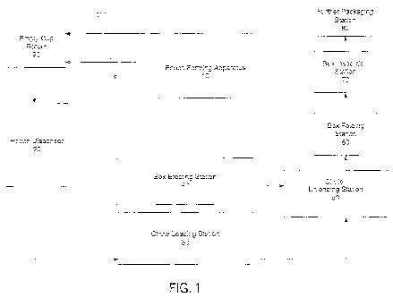
[0014] Figure 1 is a flow diagram of an apparatus and method for loading
pouch products in boxes.
[0015] Figure 2 is a top view of an apparatus for loading pouch products in
boxes.
[0016] Figure 3 is perspective view of a chute for use with the apparatus of
Figure 2.
[0017] Figure 4 is a top view illustrating the path of the plungers shown in
Figure 2.
[0018] Figure 5 is a front view of the vacuum head for use in the apparatus
of Figure 2.
[0019] Figure 6 is an illustration showing a box blank being partially
erected at a box erecting station as described herein.
[0020] Figures 7A and 7B are illustrations of the chute loading station
utilizing a cup transport system as described herein.
[0021] Figure 8 is an illustration of further packaging steps that can be
performed at the further packaging station of Figure 1.
[0022] Figure 9 is an illustration of the unloading station of Figure 1.
- 4 -
CA 02853964 2014-04-29
WO 2013/067161 PCT/US2012/063032
[0023] Figure 10 is a perspective view of an individual cup of the preferred
embodiment.
Detailed Description
[0024] In the preferred embodiment, as shown in Figure 1, a snus forming
and packaging system 101 is provided which preferably comprises a chute (or
bucket) loading station 30, a box erecting station 40 and a chute unloading
station
50. Preferably, loose product 122 (shown in Figure 2) is loaded into chutes at
the
chute loading station 30, boxes are at least partially erected at the box
erecting
station 40, and the loose product 122 is transferred from each chute into a
corresponding box at the chute unloading station 50.
[0025] In the preferred embodiment, the loose product 122 comprises oral
tobacco or non-tobacco pouch products such as those described in commonly-
owned
U.S. Patent No. 7,980,251 issued July 19, 2011 and U.S. Patent No. 7,950,399
issued May 31, 2011, the entire content of each of which is incorporated
herein by
this reference thereto.
[0026] Preferably, the pouch products are formed at a pouch forming
apparatus 10, which can be a high speed vertical form, fill and seal apparatus
or
other suitable pouch forming apparatus. In the preferred embodiment, the pouch
forming apparatus such as a vertical filling machine obtainable from Merz
Verpackungmachinen GmbH of Germany. Other suitable machines may be sourced
from Ropak Manufacturing Company of Alabama, USA, among others.
[0027] After formation, the pouch products are moved to a pouch dispenser
20, which dispenses a predetermined quantity of pouch products into individual
cups
- 5 -
CA 02853964 2014-04-29
WO 2013/067161 PCT/US2012/063032
225 (shown in Figures 7A, 7B and 10). Preferably, the predetermined quantity
is
chosen to coincide with the number of pouch products to be placed in an
individual
consumer package. In the preferred embodiment, the pouch dispenser 20
comprises
the dispenser provided on the Merz machine.
[0028] Referring now to Figure 10, the cup 225 preferably comprises a
cupped body constructed of a hard plastic of proportions akin to those of a
bottom
portion of a commercially available snus can (such as in the packaging of
loose
moist snus tobacco). Such configuration of the cup 225 promotes compatibility
of
the cup 225 with snus loading and canning machines and associated conveyors.
In
the preferred embodiment, each cup 225 is provided with an annular recess 297,
preferably adjacent its base, although other locations might be practiced.
Each cup
is opened at its top 299 and provides sufficient volume to receive a
predetermined,
desired count (or lot) of snus product.
[0029] In the preferred embodiment, the cups 225 move to the chute
loading station 30 via a cup transport system. A suitable cup transport system
is a
hook type system shown in Figures 7A and 7B. As shown in Figure 7A, cups 225
loaded with loose product are transported to the cup transport system where a
star
wheel 500 pushes each cup 225 into position for pickup by a hook 227. Each cup
225 can be picked up around a periphery 226 thereof by the hook 227 and
carried
along a third feed path 502 which is parallel to and directly above a first
feed path 4
on which the chutes 120 travel as shown in Figure 7B. Preferably the hooks 227
are
sized to releasably engage each cup 225 at its recess 297. Preferably,
multiple hooks
- 6 -
CA 02853964 2014-04-29
WO 2013/067161 PCT/US2012/063032
227 are attached to a conveyor 504 that travels horizontally in a continuous
loop in a
path resembling a racetrack. However, other suitable arrangements are
possible.
[0030] The star wheel 500 preferably moves continuously and includes a
plurality of claws 501, each of which engages a trailing side of a cup 225 as
the
latter is released from the inclined chute 505 by retraction of a pin 506,
whose
retraction is synchronized with the rotation of the wheel 500. A rail (guide)
508
guides each cup into an intersecting relation with an arriving hook 227. The
end
portion 510 of the rail 508 is spaced from working surfaces of the wheel 500
such
that the respective cup 225 is momentarily held in slight compression so that
the
arriving hook 227 engages and clasps the cup 225 about its recess 297 (Figure
10).
A biased detent 510 at the base of the hook 227 assures a releasable retention
of the
cup 225 on the hook 227.
[0031] Preferably, the hooks 227 flip the cups 225 sequentially, one at a
time, as each cup 225 is positioned above a chute 120 to dump loose product
122
into an open top 124 of the chute 120 positioned beneath and continuously
moving
with the cup 225. The empty cups are returned to the pouch dispenser 20 and
filled
again. Alternatively, the pouch products can be moved to the chute loading
station
30 by other methods and arrangements. For example, a predetermined quantity of
pouch products can be placed directly from the pouch forming apparatus 10
directly
into the chute 120 at the chute loading station 30. Arrangements with trap
doors and
other expedients are also envisioned.
[0032] At the chute loading station 30, a plurality of a chutes 120 move
horizontally along a continuous loop such that each chute 120 is repeatedly
loaded
- 7 -
CA 02853964 2014-04-29
WO 2013/067161 PCT/US2012/063032
with loose product at the chute loading station 30 and unloaded at the
unloading
station 50. In the preferred embodiment, the chutes 120 travel in spaced apart
relation along the first feed path 4 and are releasably attached to a conveyor
that
travels horizontally along a rectilinear path at the chute loading station 30
and the
chute unloading station 50. Once the chutes 120 are unloaded at the unloading
station 50, the conveyor turns downwardly so as to return the chutes 120 to
the
upstream end portion 514 of the chute loading station 30.
[0033] Preferably, each chute 120 (shown in Figures 2 and 3) is loaded
with the loose product from a single cup 225 (shown in Figure 7). The chute
120
then moves along the first feed path 4 to the chute unloading station 50 where
the
loose product is transferred from the chute 120 into a corresponding box 44.
[0034] As shown in Figure 3, each chute 120 has an open top 124, an open
upstream end 126, and an open downstream end 128. The open top 124 is sized
and
configured to allow for placement of loose product 122 into the chute 120 at
high
speed as the chute moves along the first feed path 4 and the cup 225 moves
along the
third feed path 502. Moreover, the open top 124 can include substantially
vertical
sidewal Is 164 extending around the periphery of the open top 124 and inclined
end
walls 125, 127. The sidewalls 164 can be formed at an angle so as to form a
funnel
through which the loose product 122 travels as it enters the chute 120.
Moreover,
the sidewalls 164 can be preferably about 0.5 inch to about 3.0 inches in
height.
[0035] Preferably, the inner surface 220 of each chute 120 includes a non-
stick coating so as to substantially prevent loose product from sticking to
the inner
- 8 -
CA 02853964 2014-04-29
WO 2013/067161
PCT/US2012/063032
surface 220 of the chute 120. Preferably, each chute 120 is releaseably
attached to
its conveyor to facilitate removal for cleaning.
[0036] As noted above, loose product 122 is released into the open top 124
from a corresponding cup 225 as the cup 225 travels in a superposed relation
to a
respective chute 120. In the preferred embodiment, each cup 225 and a
respective
chute 120 are superposed and travel at the same speed. Thus, the cups 225
travel
along a linear path (the third feed path 502), which is parallel to the first
feed path 4
along which the chutes 120 travel. The apparatus is arranged such that each
cup 225
is flipped over to release product while a chute 120 is aligned beneath the
cup.
[0037] Referring now to Figure 7B, each hook 227 preferably is subject to
the action of a cam follower 851; which when progressed into a recess 853 of
the
guide 855, causes the hook 225 to flip. The cup 225 then continues along in an
upside down relation with the hook 227 now leading the cup 225. This
relationship
is maintained until the cup 227 is plowed off the hook by a rail or other
suitable
contrivance onto a conveyor, which returns the cups 225 to the pouch dispenser
20
in an upside down condition. Return conveyance in an upside-down condition
avoids collection of dust or dirt and assures emptiness for the next loading
cycle.
The pouch dispenser 20 includes a rail to flip each cup 225 into right-side up
orientation prior to reloading of the cup 225.
[0038] At or about the same time as the chute 120 is loaded with loose
product 122, a box 44 (shown in Figure 2) is at least partially erected at a
box
erecting station 40. In the preferred embodiment, each box 44 is a side-
loading,
inner box such as that described in commonly-owned Non-Provisional Patent
- 9 -
CA 02853964 2014-04-29
WO 2013/067161 PCT/US2012/063032
Application Serial No. 13/325,803 filed December 14, 2011, the entire content
of
which is incorporated herein by reference thereto. Alternatively, the box 44
can be
loaded via a top or bottom openings or the box 44 can be an outer box.
[0039] In the preferred embodiment, the box blank is in a flattened
condition, with top and front panels superimposed over and connected with
bottom
and back panels, and with dust flaps 159 and side flaps 160 disposed within
the
general plane of the flattened blank.
[0040] Preferably, a rotary blank feed 42 feeds box blanks from a hopper
43. Each blank 162, as shown in Figures 2 and 6, is erected to form a box 44
along
a second feed path 8, which is substantially parallel to the first feed path
4. Once the
box 44 is erected, plows and tuckers open the dust flaps 159 and the side
flaps 160
outwardly to expose a first open side 150 and a second open side 152. The
erected
box 44 then moves along the second feed path 8 to the chute unloading station
50.
[0041] In the preferred embodiment, the box erecting station 40 further
includes a conveyor 400 (shown in Figure 2) for moving boxes 44 along the
second
feed path 8. Preferably, the box erecting apparatus also includes a support
bar 506
(shown in Figure 9) which is operable to hold erected boxes 44 open while
traveling
along the second feed path 8.
[0042] Preferably, the second feed path 8 travels substantially parallel to
and at the same speed as the first feed path 4 so that each box 44 has a
corresponding chute 120 with which to mate at the chute unloading station 50.
Thus, at the chute unloading station 50, the second open side 152 of the box
44 is
- 10-
CA 02853964 2014-04-29
WO 2013/067161 PCT/US2012/063032
aligned with a downstream end 128 of the chute 120 and the first open side 150
of
the box is in contact or proximate with a face 200 of a vacuum head 200.
[0043] Referring now to Figures 2 and 9, once the chutes 120 reach the
chute unloading station 50, the chutes 120 travel under a stationary lid 105,
which
may contact upper edges 95 of the open top 124 and/or sidewalls 164 of the
chute
120. Typically, the lid 105 does not form a seal, but does substantially close
off the
open top 124 of the chute 120. Preferably, the lid 105 includes multiple
spaced apart
air inlets 110, each of which lines up with the open top 124 of a chute 120 as
it
passes underneath the lid 105. Preferably, the air inlets 110 are connected to
a
pressurized air source 112, which provides a pulse of air to the chute 120.
Preferably, the pulse of air is timed with alignment of the chute 120
underneath the
air inlet 110. The pulse of air agitates the loose product 122 disposed within
the
chute 120 as vacuum is applied so as to ensure that the entire predetermined
quantity
of loose product 122 is transferred from the chute 120 into the confines of
the
opened box 44. The agitation also assures that product does not form a
blocking
mass of product or "bridges" the chute 120. Agitation can be achieved instead
by or
supplemented with mechanical arrangements (e.g., vibratory plates or pins) or
electromechanical arrangements such as with ultrasonic devices. The pulses of
air
of the preferred embodiment are preferably at or about approximately 2 or 3
psi,
when packaging snus.
[0044] Also preferably, the unloading station 50 includes a stationary
vacuum head 200 in communication with the second open side 150 of each box 44.
The vacuum head 200 in the preferred embodiment is about 1 foot to about 4
feet in
- 11 -
CA 02853964 2014-04-29
WO 2013/067161
PCT/US2012/063032
length when packaging pouched snus and each box 44 travels along the length of
the
vacuum head 200 while suction is applied.
[0045] In the preferred embodiment, a source of vacuum 102 comprises a
vacuum pump connected to the vacuum head (plenum) 200 to provide a continuous
vacuum source along the second feed path 8. When packaging pouched snus, the
vacuum pump preferably is capable of drawing air at a rate in the range of
approximately 300 to 500 cubic feet per minute. In practice, a vacuum pump of
10
horsepower with a rating of 420 cfm and capability to draw vacuum of 100
inches of
water should suffice for snus product. Such arrangement provides sufficient
vacuum
to the product through the vacuum head 200 at the second open side 150 of each
box
44 so as to pull loose product 122 from the chute 120 into the interior of
each box
44, essentially without compressing the product.
[0046] In the
preferred embodiment, as shown in Figure 5, the vacuum
head (plenum) 200 has a face 100 which includes a screen 101 having openings
sized to substantially prevent suction of loose product 122 into the vacuum
head 200
as vacuum is applied.
[0047] Preferably, the vacuum plenum 200 is located downstream of where
loose product 122 is released from a cup 225 into a chute 120. Preferably,
agitation
of product occurs as vacuum begins to be communicated through the chute 120 to
the product 122.
[0048] In the preferred embodiment, about three chutes 120 are unloaded at
a time. However, more or fewer chutes 120 could be unloaded at a time
depending
upon the length of the vacuum head 200 and the spacing between the chutes 120.
- 12 -
CA 02853964 2014-04-29
WO 2013/067161
PCT/US2012/063032
[0049] Also in the preferred embodiment, as shown in Figure 2, the open
upstream end 126 of the chute 120 is sized to accept a plunger 114
therethrough.
Preferably, the apparatus includes a plurality of plungers 114, which travel
along a
fourth feed path 505. In the preferred embodiment there are three plungers.
The
plungers 114 are reciprocal and move forward to position B' (shown in Figure
4)
after suction has been applied and the loose product 122 has substantially
been
moved from the chute 120 and into the box. 44. Each plunger 114 moves forward
and through each corresponding chute 120 such that the plunger 114 enters the
corresponding box 44 only slightly, preferably only about 2 mm to about 4 mm.
The plungers do not travel further into the box 44 to avoid compression of the
loose
product 122. After moving into the box 44, the plunger 114 then moves with the
chute 120 to position B" before moving out of the chute 120 to position B" and
finally back to initial position B" where the plunger 114 waits for the next
corresponding chute 120. The three plungers of the preferred embodiment move
with the chutes to which they correspond and move together to return to
position B".
Action of the plungers assures clearance of product from the chutes 120 and
complete delivery into the interior spaces of the opened boxes.
[0050] Once the box 44 is filled with loose product 122, the box dust and
side and flaps 159, 160 are optionally glued and folded at the box folding
station 60
to close and optionally seal the box 44. The box 44 is then inspected at the
box
inspection station 70 to check for holes, improper seals, and the like.
[0051] As shown in Figure 8, the box 44 can then travel to the further
packaging station 80, where the box 44, can be placed in an outer box 82. In
- 13 -
CA 02853964 2014-04-29
WO 2013/067161
PCT/US2012/063032
addition, overwrap can be applied to the outer box 82 to maintain freshness of
the
loose product 122. The overwrap can be formed of any suitable plastic or foil
material. Meanwhile, the cups used to deliver product to the chutes are
returned 90
to the pouch dispenser 20.
[0052] By such arrangement as described above, snus and other loose
product may be loaded into a box or other container with a more complete,
uniform,
homogeneous and efficient disposition of the loose product within the
container.
Undesirable and troublesome headspace is avoided. Smaller containers can be
used
for the same amount of product, which may lead to significant savings in
packaging
materials and space requirements in displaying product at retail. The
arrangement
provides high speed production capability, particularly with boxing of pouched
snus
product.
[0053] In another preferred embodiment, a method of filling or loading
boxes with loose product(s) is provided. Broadly speaking, the method includes
establishing a procession of package structures, each of which has first and
second
openings and an interior space or volume. Establishing the procession of
package
structures may also include folding open flaps of a package. In addition, the
method
includes repetitively establishing predetermined quantities of loose product
and
repetitively disposing said quantities at locations adjacent said first
openings. That
repetitive disposition of quantities may include loading loose products into
chutes in
spaced apart relation. Each chute has an open top, an open upstream end, and
an
open downstream end. The open top is operable to receive loose product while
moving along a first feed path. The method also includes aligning boxes in
spaced
- 14-
CA 02853964 2014-04-29
WO 2013/067161 PCT/US2012/063032
apart relation, each box having a first and second open side, and aligning the
first
open side of each box with the open downstream end of a corresponding chute
while
moving the boxes along a second feed path. Preferably, the second feed path is
parallel to the first feed path.
[0054] Also preferably, the method includes transferring or unloading
disposed quantities of loose product from each chute into the interior space
of a
corresponding box by applying or communicating a vacuum through the second
open side of each box so as to pull loose product from the chute and into the
box.
The transferring step may further include moving the open package along a
vacuum
plenum.
[0055] Preferably, the step of transferring of loose product by
communicating a vacuum includes agitating the loose product while applying
vacuum. In the preferred embodiment, the method can include covering the open
top of each chute with a lid as or prior to applying vacuum and providing at
least one
air inlet in the lid operable to deliver air from a pressurized air source to
each chute
to agitate product as vacuum is applied.
[0056] Preferably, the method can also include purging the chute or
passage or errant product by advancing a plunger through the upstream end of
the
chute, through the downstream end of the chute, and into the corresponding box
thereby assuring complete transfer of loose product to the box. Preferably the
plunger is advanced into the interior of the box slightly, such that
mechanical
compression of product is avoided or minimized. Also preferably, the plunger
is
plunged only about 2 mm to about 4 mm into the erected box.
- 15 -
CA 02853964 2014-04-29
WO 2013/067161 PCT/US2012/063032
[0057] When the product has been loaded into the box, the method also
includes closing the first and second openings of the box.
[0058]In this specification, the word "about" is often used in connection with
numerical values to indicate that mathematical precision of such values is not
intended. Accordingly, it is intended that where "about" is used with a
numerical
value, a tolerance of 10% is contemplated for that numerical value.
[0059] While the foregoing describes in detail an apparatus and method for
packaging loose product with reference to a specific embodiment thereof, it
will be
apparent to one skilled in the art that various changes and modifications and
equivalents to the apparatus and method may be employed, which do not
materially
depart from the spirit and scope of the invention.
-16-