Note: Descriptions are shown in the official language in which they were submitted.
CA 02854652 2014-05-06
WO 2013/067599
PCT/AU2012/001389
- 1 --
WAVELENGTH VERSATILE VECSEL RAMAN LASER
FIELD Of THE INVENTION
[0001] The present invention relates to methods and apparatus for enhancing
the
spectral coverage of optically pumped semiconductor lasers. The present
invention
further relates to tuneable Raman laser apparatus and methods of operation of
tuneable
Raman laser systems.
BACKGROUND
[00021 Any discussion of the background art throughout the specification
should in no
way be considered as an admission that such art is prior art, nor that such
background art
is widely known or forms part of common general knowledge in the field.
[0003] Optically-pumped semiconductor vertical-external-cavity surface-
emitting
lasers (VECSELs) have evolved rapidly during the past decade. An extensive
discussion
is contained in M. Kuznetov, Semiconductor Disk Lasers: Physics and
Technology. Wiley
Online Library. Chap. 1 (2010). VECSELs are a very versatile type of laser,
because a
wide range of semiconductor materials can deliver a selection of emission
wavelengths
and tunability, and because the open cavity design enables easy integration of
intracavity
components and nonlinear processes. From a single VECSEL, the direct emission
has
ranged from violet at 390 nm [21 to mid-infrared [3], and output powers up to
40 W
output power have been reported to date [4].
[00041 Intracavity second harmonic generation (SHG) is well established as
a means of
substantially expanding the spectral coverage of VECSELs, and the yellow
region is one
that has been particularly targeted [5]. Intracavity-doubled VECSELs also
benefit from
the short carrier life time in semiconductors (typically a few ns) and the
lack of spatial
hole burning in the periodic gain structure, and therefore their output has
low amplitude
noise. This is in contrast to the so-called "green problem" [6], in which
longitudinal-mode
competition often causes strong intensity noise in intracavity doubled
conventional solid-
CA 02854652 2014-05-06
WO 2013/067599
PCT/A1J2012/001389
¨ 2 ¨
state lasers. Other inh-acavity second-order nonlinear processes that have
been reported
for VECSELs are optical parametric oscillation [7] and difference frequency
generation [8].
[0005] Recently, l'arrotta et al. has demonstrated a VECSEL- pumped
intracavity
continuous ¨wave (cw) Raman laser [9], in a new approach to combine the
tunability from
VECSELs with wavelength shifting from stimulated Raman scattering (SRS). They
pumped a KGW crystal within a VECSEL cavity and shifted the fundamental
emission
around 1.06 p.m to 1.14 pm, with a tunable range from 1133-1157 nun.
SUMMARY OF THE INVENTION
[0006] It is an object of the present invention to provide an improved form
of optically
pumped semiconductor laser. It is another object of the invention to provide
an improved
form of tunable laser system.
[0007] It is a further object of the present invention to overcome or
ameliorate at least
one of the disadvantages of the prior art, or to provide a useful alternative.
[00081 In accordance with a first aspect of the present invention, there is
provided a
tunable lasing device. The tunable lasing device may comprise a vertical
external cavity
surface emitting laser, adapted to generate a fundamental laser beam in
response to
pumping from a pump source, the fundamental laser beam having a tunable
fundamental
wavelength and a fundamental linewidth. The tunable lasing device may further
comprise a fundamental resonator cavity adapted to resonate the fundamental
beam
therein. The tunable lasing device may further comprise a first optical
element located
within the fundamental resonator cavity for control of the fundamental
linewidth of the
fundamental beam. The first optical element may additionally be adapted for
tuning the
wavelength of the fundamental beam. The fundamental resonator cavity may
comprise
said external cavity of said vertical external cavity surface emitting laser.
The tunable
lasing device may further comprise a Raman resonator cavity located at least
partially in
the fundamental resonator cavity and coupled therewith. The Raman resonator
may be
adapted to receive the fundamental beam, The Raman resonator may comprise a
solid
state Raman active medium located therein for generating at least a first
Stokes beam
CA 02854652 2014-05-06
WO 2013/067599
PCT/AU2012/001389
¨ 3 ¨
from the fundamental beam. The Raman resonator cavity may be adapted to
resonate the
Stokes beam therein. The Raman resonator may be further adapted to emit an
output
beam. The Raman resonator may further comprise a nonlinear medium located
therein
for nonlinear frequency conversion of at least one of the beams present in
said Raman
resonator cavity thereby generating a frequency converted beam. The tunable
lasing
device may further comprise an output coupler adapted to emit an output beam.
The
output beam may be at least a portion of the frequency converted beam derived
from at
least one of the resonating beams in either the fundamental or Raman resonator
cavities.
[0009] According to an arrangement of the first aspect, there is provided a
tunable
lasing device comprising: a vertical external cavity surface emitting laser,
adapted to
generate a fundamental laser beam in response to pumping from a pump source,
the
fundamental laser beam having a tunable fundamental wavelength and a
fundamental
linewidth; a ; a fundamental resonator cavity adapted to resonate the
fundamental beam
therein; a first optical element located within the fundamental resonator
cavity for control
of the fundamental linewidth of the fundamental beam; a Raman resonator cavity
located
at least partially in the fundamental resonator cavity and coupled therewith,
the Raman
resonator adapted to receive the fundamental beam and comprising therein: a
solid state
Raman active medium for generating at least a first Stokes beam from the
fundamental
beam wherein said Raman resonator cavity is adapted to resonate said Stokes
beam
therein and further adapted to emit an output beam; and a nonlinear medium
located
therein for nonlinear frequency conversion of at least one of the beams
present in said
Raman resonator cavity thereby generating a frequency converted beam; said
tunable
lasing device further comprising an output coupler adapted to emit an output
beam, the
output beam comprising at least a portion of said frequency converted beam
derived from
at least one of the resonating beams in the fundamental or the Raman resonator
cavities..
[00101 The solid state Raman active medium may be located within both the
Raman
resonator cavity and the fundamental resonator cavity. The fundamental beam
may be a
continuous wave (cw) beam. In alternate arrangements the fundamental beam may
be a
pulsed beam. In a particular arrangement the fundamental cavity may comprise a
Q-
CA 02854652 2014-05-06
WO 2013/067599
PCT/AU2012/001389
¨ 4 ¨
switch element for generating the pulsed fundamental beam The Q-switch may be
located in the fundamental resonator cavity. In particular arrangements, the Q-
switch
element may be either an active Q-switch, a passive Q-switch or alternative
element for
generating a Q-switched fundamental beam as would be a appreciated by the
skilled
addressee. In alternate arrangements the fundamental beam may be a modelocked
beam
and the fundamental resonator cavity may comprise a mode-locking element for
generating the modelocked fundamental beam pulses. In particular arrangements
the
modelocked beam may be generated by one or more elements in the fundamental
resonator cavity to form a Kerr-lens modelocked fundamental beam.
Alternatively, the
fundamental resonator may comprise a saturable absorber to generate the mode-
locked
fundamental beam pulses. Therefore, the Stokes beam and the frequency
converted beam
may also be cw or pulsed beams depending on whether the fundamental beam is a
cw or
pulsed beam respectively. The fundamental resonator cavity may be a high
finesse
resonator cavity at the wavelength of the fundamental beam. The fundamental
resonator
cavity may be a high finesse resonator cavity at the wavelengths of the
fundamental
beam. The fundamental resonator cavity my simultaneously be a low finesse
resonator
cavity at the wavelength(s) of the frequency converted beam. The Raman
resonator may
be a high finesse resonator cavity at the wavelength(s) of the Raman-shifted
(Stokes)
beam(s) (e.g. the first Stokes beam or higher order Stokes beams generated by
cascaded
Raman shifting of previously Raman shifted beam(s) in the resonator cavity
e.g. having
for example second- or third-Stokes wavelengths). The Raman resonator cavity
may
simultaneously be a low finesse resonator cavity at the wavelength(s) of the
frequency
converted beam. Raman resonator at least partially overlaps the fundamental
resonator ¨
the portion of the Raman resonator which contains the Raman material must be
within
the fundamental resonator R res can extend beyond.
[0011] The Raman resonator cavity may be coupled to the fundamental
resonator
cavity. The Raman resonator cavity may be at least partially contained within
the
fundamental resonator. For example, the Raman resonator cavity may be wholly
located
within the fundamental resonator. Alternatively, the Raman resonator cavity
may be only
partially located within the fundamental resonator cavity. For example the
Raman
CA 02854652 2014-05-06
WO 2013/067599
PCT/AU2012/001389
¨ 5 ¨
resonator cavity may partially located external to the fundamental resonator
cavity. For
instance, the fundamental cavity may comprise a mirror (reflector) located
therein which
comprises a first end mirror for the Raman resonator cavity ¨ the first end
mirror typically
will be highly transmissive at the wavelengths of the tunable fundamental beam
and
simultaneously highly reflective at the wavelengths of the Raman shifted
beam(s) - and a
further mirror (reflector) may be located external to the fundamental
resonator which
comprises a second end mirror for the Raman resonator cavity. In this
arrangement, the
Raman resonator typically will comprise therein a mirror (reflector) which
comprises an
end mirror of the fundamental resonator cavity. The end mirror of the
fundamental
resonator cavity located within the Raman resonator will typically be highly
transmissive
at the wavelength(s) of the Raman shifted beam(s) and simultaneously highly
reflective at
the wavelengths of the fundamental beam.
[0012] The first optical element for control of the fundamental linewidth
of the
fundamental beam may, for example, be one or more birefringent filters and/or
one or
more intracavity etalons located in the fundamental resonator cavity.
[0013] The vertical external cavity surface emitting laser (VECSEL) may be
a
semiconductor device capable of generating a laser emission when optically
pumped
from an external pump source. The laser emission generated by the optically
pumped
semiconductor device may comprise the fundamental laser beam. The laser
emission
generated by the optically pumped semiconductor device may be tunable thereby
providing a tunable fundamental laser beam. The tunable fundamental beam may
resonate (i.e. circulate) within the fundamental resonator cavity.
[0014] The tunable lasing device may be adapted to generate a tunable
output beam
having a wavelength in the visible optical spectrum. The wavelength of the
output beam
may be between about 470nm and about 630ruu. The tunable lasing device may be
adapted to generate a tunable output beam having a wavelength in either the
blue, green
or yellow regions of the visible optical spectrum. The output wavelength of
the tunable
lasing device may be selected from the ranges including, for example, between
about
440nm to 500 nm, or between about 500nm to 550 nm, or between about 550 nm to
590
CA 02854652 2014-05-06
WO 2013/067599
PCT/AU2012/001389
¨ 6 ¨
rim. In an alternate arrangement, the output wavelength of the tunable lasing
device may
be continuously tunable between about 470nm and about 520 urn. In alternate
arrangements the wavelength of the output beam may be selected to lie within
the orange
or red regions of the visible spectrum. That is, the output wavelength of the
tunable
lasing device may alternately be selected from the range including, for
example, between
about between about 590 nm to about 650 nm.
[00151 In a particular arrangement, the tunable lasing device may be
adapted to
generate an output beam having a wavelength selectable from the group
comprising: a
wavelength in the blue region of the spectrum; a wavelength in the green
region of the
spectrum; and a wavelength in the yellow region of the spectrum. For instance,
in a first
mode of operation, the lasing device is configured such that the wavelength of
the output
beam lies within the blue region of the visible optical spectrum; in a second
mode of
operation, the lasing device is configured such that the wavelength of the
output beam
lies within the green region of the visible optical spectrum; and in a third
mode of
operation the lasing device is configured such that the wavelength of the
output beam lies
within the yellow region of the visible optical spectrum. In each mode of
operation, the
wavelength of the output beam may be further tunable about a discrete range of
wavelengths in each of the blue, green or yellow regions of the visible
optical spectrum
with respect to the selected mode of operation. In this manner, the lasing
device disclosed
herein may act as a replacement for three independent laser systems wherein
each of
those independent systems are adapted for output of a single wavelength only
i.e. either a
blue, green or yellow wavelength. Merely by tuning of the lasing device of the
present
application, the lasing device may select a desirable output wavelength for a
particular
task i.e. either a blue, green or yellow wavelength. Tuning of the laser
device to select the
desired wavelength of the output beam may comprise one or more of: tuning of
the
wavelength of the fundamental beam generated by the vertical external cavity
surface
emitting laser; or tuning the Raman-active medium to select a desired Raman-
shift of the
fundamental beam (i.e. in arrangements where multiple Raman transitions are
available
in the Raman-active medium e.g. using KGW as the Raman active medium having
selectable characteristic Raman shifts of either 768cm-I or 901cm-1); or
tuning of the
CA 02854652 2014-05-06
WO 2013/067599
PCT/AU2012/001389
¨ 7 ¨
nonlinear medium for selective frequency conversion of one or more of the
wavelengths
in the Raman resonator cavity (e.g. via SHG, SFG or DFG) thereby to obtain a
frequency
converted beam having the desired wavelength and outputting at least a portion
o f the
frequency converted beam as an output beam having the desired wavelength.
[0016] In a further particular arrangement, the tunable lasing device may
be adapted to
generate an output beam having a wavelength selectable from the group
comprising: a
wavelength in the green region of the spectrum; a wavelength in the yellow
region of the
spectrum; and a wavelength in the red region of the spectrum.
[0017] In a further particular arrangement, the tunable lasing device may
be adapted to
generate an output beam having a wavelength selectable from the group
comprising: a
wavelength in the blue region of the spectrum; and a wavelength in the green
region of
the spectrum.
[0018] In a further particular arrangement, the tunable lasing device may
be adapted to
generate an output beam having a wavelength selectable from the group
comprising: a
wavelength in the green region of the spectrum; a wavelength in the yellow
region of the
spectrum.
[0019] In an alternate arrangement, the tunable lasing device may be
adapted to
generate a tunable output beam having a wavelength in either the green, yellow
or
orange/red regions of the visible optical spectrum. The output wavelength of
the tunable
lasing device may be selected from the ranges including, for example, between
about 510
nm to 550 nm, or between about 555 nm to 575 nm, or between about 575 nm to
650 nm.
In an alternate arrangement, the output wavelength of the tunable lasing
device may be
continuously tunable between about 520 nm and about 560 nm.
[0020] In any of the aspects and arrangements of the tunable lasing device
disclosed
herein, the output wavelength of the tunable lasing device may be selected by
tuning
either: the wavelength of the fundamental beam; or tuning of the Raman-active
medium
to select a desired Raman-shift of the fundamental beam; or tuning (e.g.
either
CA 02854652 2014-05-06
WO 2013/067599
PCT/AU2012/001389
- 8 ¨
temperature or angle tuning) of the nonlinear medium or any combination of two
or more
of such tuning methods..
[0021.] Preferably the device further includes a nonlinear optical crystal
within the
resonator cavity for producing a frequency converted beam derived from either:
the
fundamental beam, the Raman beam, or both the fundamental and Raman beams. The
frequency converted beam may be obtained by second harmonic generation and/or
sum
frequency or difference frequency generation of the fundamental beam and/or
the Stokes
beam within the cavity and outputting thereof. At least one mirror of the
resonator cavity
may be adapted to output the frequency converted beam.
[0022] Preferably, the first filter can comprise a birefringent element,
the Raman
resonator can comprise a Potassium Gadolinium Tungstate (KGW) crystal, and the
nonlinear crystal can be a Lithium Triborate Crystal.
[0023] In accordance with a further aspect of the present invention, there
is provided a
method of extending the frequency of an optically pumped intro cavity tunable
laser, the
method including the steps of: generating intro cavity stimulated Raman
scattering to
generate a first Stokes wavelength; and converting the Stokes wavelength by
intra cavity
sum frequency generation (SFG), difference frequency (DFG)or second harmonic
generation (SHG) to a second wavelength range.
[0024] Preferably, the tunable laser can be optically pumped by a VECSEL
laser. The
method can also include the steps of: generating a second Stokes wavelength;
and
converting the second Stokes wavelength by intra cavity nonlinear frequency
generation
techniques (including, for example, sum frequency generation, second harmonic
generation or third harmonic generation) to thereby generate at least a third
wavelength
range
[0025] In accordance with a further aspect of the present invention, there
is provided
an optically pumped semiconductor VECSEL pumped, intra cavity KGW Raman
tunable
laser with intracavity nonlinear mixing. The intro cavity nonlinear mixing
preferably can
include outputting into two separate tunable emission bands. The tunable
emission
CA 02854652 2014-05-06
WO 2013/067599
PCT/AU2012/001389
- 9 -
bands may comprise a first band generated by sum frequency generation and a
second
band may be generated by second harmonic generation. The tuning may be through
temperature tuning of an intra cavity LBO crystal.
[0026] In accordance with a further aspect, there is provided a laser
system comprising
a vertical-external-cavity surface-emitting laser device adapted for
generating a tunable
laser beam tuneable within one or more frequency ranges. The laser system may
further
comprise a Raman active medium and a nonlinear medium adapted for selectably
generating one or more frequency converted beams derived from said fundamental
laser
beam thereby to permit the laser system to output laser wavelengths tunable
within a
plurality of discrete frequency ranges.
[0027] In an arrangement of any one of the above aspects, the Raman
resonator cavity
may have a high finesse at the optical wavelengths of the Raman beam and,
simultaneously, a low finesse at the optical wavelength of the frequency
converted beam.
The finesse of the Raman resonator cavity at the wavelength of the Raman beam
may be
greater than 100. In other arrangements, the finesse of the Raman resonator
cavity at the
wavelength of the Raman beam may be greater than 500, or greater than 1000,
greater
than 2000, greater than 3000, greater than 4000, greater than 5000, greater
than 6000,
greater than 7000, greater than 8000, greater than 9000, greater than 10000,
greater than
15000, greater than 20000, greater than 25000, greater than 30000, greater
than 35000,
greater than 40000, greater than 45000. The finesse of the Raman resonator
cavity at the
wavelength of the Raman beam may be in the range 100 to 50000, 100 to 45000,
100 to
40000, 100 to 35000, 100 to 30000, 100 to 25000, 100 to 20000, 100 to 15000,
100 to 10000, 100
to 9000, 100 to 8000, 100 to 7000, 100 to 6000, 100 to 5000, 100 to 4000, 100
to 3000, 100 to
2000, 100 to 1000, or 100 to 500, and may be approximately 100, 150, 200, 250,
300, 350, 400,
450, 500, 550, 600, 650, 700, 750, 800, 850, 900, 950, 1000, 1100, 1200, 1300,
1400, 1500, 1600,
1700, 1800, 1900, 2000, 2250, 2500, 2750, 3000, 3250, 3500, 3750, 4000, 4250,
4500, 4750, 5000,
6000, 7000, 80000, 9000, 10000, 11000, 12000, 13000, 14000, 15000, 16000,
17000, 18000,
19000, 20000, 25000, 30000, 35000, 40000, 45000, 50000. In an arrangement of
any one of
the above aspects, the Raman resonator cavity has a high Q at the wavelengths
of the
CA 02854652 2014-05-06
WO 2013/067599
PCT/AU2012/001389
- 10 ¨
optical wavelengths of the Raman beam. The Raman resonator cavity may
simultaneously have a low finesse at the optical wavelength of the frequency
converted
beam. The Raman resonator cavity may have both a high finesse and a high Q at
the
optical wavelengths of the optical wavelengths of the Raman beam. The Raman
resonator
cavity may have both a low finesse and a low Q at the optical wavelength of
the
frequency converted beam. In an arrangement of any one of the above aspects,
the
Raman resonator cavity may have a finesse at the wavelength of the frequency
converted
beam in the range of approximately 0 to 5. In a further arrangement, the Raman
resonator
cavity finesse at the wavelength of the frequency converted beam may be in the
range of
approximately 0 to 4.5, 0 to 4, 0 to 3.5, 0 to 3, 0 to 2.5, 0 to 2.4, 0 to
2.3, 0 to 2.2, 0 to 2.1, 0 to
2.0, 0 to 1.9, 0 to 1.8, 0 to 1.7, 0 to 1.6, 0 to 1.5, 0 to 1.4, 0 to 1.3, 0
to 1.2, 0 to 1.L 0 to 1.0, 0 to
0.9, 0 to 0.8, 0 to 0.7, 0 to 0.6, 0 to 0.5, 0 to 0.4, 0 to 0.3, 0 to 0.2, 0
to 0.1, 0.5 to 5, 0 to 4.5, 0 to
4, 0.5 to 3, 0.5 to 3.5, 0,5 to 2, 0.5 to 1.5, 0.5 to 1.0, Ito 4, 0 to 3, 1 to
2.5, 1 to 2, and the
resonator finesse at the wavelength of the frequency converted beam may be
approximately 0.1, 0.2, 0.3, 0.4, 0.5, 0.6, 0.7, 0.8, 0.9, 1.0, 1.1, 1.2, 1.3,
1.4, 1.5, 1.6, 1.7, 1.8, 1.9,
2,0, 2.1, 2.2, 2,3, 2.4, 2.5, 2,6, 2.7, 2.8, 2.9, 3.0, 3.5, 4.0, 4.5 or 5.
[0028] In an
arrangement of any one of the above aspects, the Raman resonator cavity
may have a roundtrip resonator loss, 4, at the wavelength of the Raman beam in
the
range of 0% to 5%. As discussed below, the round-trip resonator loss, Lx,
comprises all
intracavity optical losses experienced by a laser beam resonating in the
resonator cavity at
a particular wavelength, i.e. the round-trip resonator loss, Lx, comprises
loss components
from the mirror reflectivities of the cavity mirrors as well as additional
loss components
due to elements within the resonator cavity including for example,
scattering/reflection
losses from the elements of the resonator cavity. That is, the round-trip
resonator loss, L,
comprises all losses experienced by a resonating beam in the cavity as it
circulates
through the resonator cavity and the elements contained therein. In further
arrangements, the roundtrip resonator loss at wavelength of the Raman beam may
be in
the range of 0% to 4.5%, 0% to 4%, 0% to 3.5%, 0% to 3%, 0% to 2.5%, 0% to 2%,
0% to
1.9%, 0% to 1.8%, 0% to 1.7%, 0% to 1.6%, 0% to 1.5%, 0% to 1.4%, 0% to 1.3%,
0% to 1.2%,
0% to 1.1%, 0% to 1.0%, 0% to 0.9%, 0% to 0.8%, 0% to 0.7%, 0% to 0.6%, 0% to
0.5%, 0% to
11
0.3%, 0% to 0.2%, or 0% to 0.1%. In an arrangement of any one of the above
aspects, the
roundtrip resonator loss at the wavelength of the Raman beam may be
approximately 0%,
0.1%, 0.2%, 0.3%, 0.4%, 0.5%, 0.65%, 0.7%, 0.8%, 0.9%, 1.0%, 1.1%, 1.2%, 1.3%,
1.4%, 1.5%,
1.6%, 1.7%, 1.8%, 1.9%, 2.0%, 2.5%, 3.0%, 3.5%, 4.0%, 4.5%%, or 5%.
[0028a] In accordance with a further aspect there is provided a tunable lasing
device
comprising: a vertical external cavity surface emitting laser (VECSEL),
adapted to
generate a fundamental laser beam in response to pumping from a pump source,
said
fundamental laser beam having a fundamental wavelength and a fundamental
linewidth;
a fundamental resonator cavity defined by at least first and second reflective
elements
adapted to resonate the fundamental laser beam therein; a first optical
element
comprising one or more birefringent filters and/or one or more etalons located
within the
fundamental resonator cavity adapted for control of the fundamental linewidth
of the
fundamental laser beam; a Raman resonator cavity located at least partially in
said
fundamental resonator cavity and coupled therewith, the Raman resonator cavity
being
defined by at least two reflective elements, wherein at least one of the
reflective elements
is different from the first and second reflective elements and wherein the
first optical
element is separate from the Raman resonator cavity, the Raman resonator
adapted to
receive the fundamental laser beam and comprising therein: a solid state Raman
active
medium located in said Raman resonator cavity for generating at least a first
Stokes beam
from the fundamental laser beam, wherein said Raman resonator cavity is
adapted to
resonate said Stokes beam therein and produce a continuous wave output beam,
and
a nonlinear medium located in said Raman resonator cavity for nonlinear
frequency
conversion of at least one of the beams present in said Raman resonator cavity
thereby
generating at least one continuous wave frequency converted beam,
CA 2854652 2018-12-21
- ha-
wherein one of said reflective elements is an output coupler that is
transmissive at one or
more predefined wavelengths ranges corresponding to the wavelengths of said
output
beam, said output beam comprising at least a portion of said frequency
converted beam
derived from at least one of the beams resonating in said fundamental
resonator cavity or
said Raman resonator cavity, and wherein said output beam is continuously
tunable
within the one or more predefined wavelength ranges by selective adjustment of
one or
both of the nonlinear medium and the first optical element.
[0028b] In accordance with a further aspect there is provided a method of
extending the
frequency output of an optically pumped intra cavity tunable laser, the method
comprising the steps of: pumping a semiconductor device configured to generate
a
tunable fundamental laser beam as a result of said pumping; providing a
fundamental
resonator cavity for resonating the tunable fundamental laser beam; providing
a Raman
resonator cavity at least partially overlapping with the fundamental resonator
cavity;
providing a Raman active medium within said Raman resonator cavity for
generating
intra cavity stimulated Raman scattering to generate a first Stokes wavelength
derived
from the fundamental laser beam; providing a nonlinear medium within the Raman
resonator cavity for converting the Stokes wavelength by intra cavity sum
frequency
generation or second harmonic generation to a frequency converted wavelength
range;
and outputting the frequency converted wavelengths.
CA 2854652 2018-12-21
- lib-
BRIEF DESCRIPTION OF THE DRAWINGS
[0029] Preferred embodiments of the invention will now be described, by way
of
example only, with reference to the accompanying drawings in which:
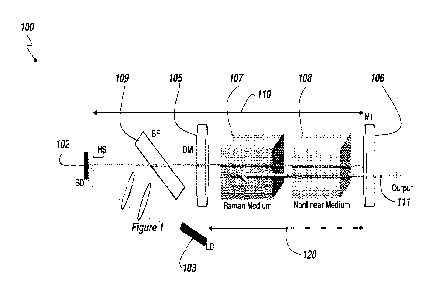
[0030] Figure 1 illustrates schematically an arrangement of a VECSEL pumped
CW
Raman laser;
[0031] Figure 2 illustrates the output and intra cavity power of the Stokes
and
fundamental wavelength versus absorbed pump power, with the insert showing the
normalized Stokes output tuning by BF rotation;
[0032] Figure 3 illustrates the tuning of visible emissions from 577.5-596
nm by SHG
and from 548.5-566 nm by SFG;
[0033] Figure 4 illustrates a power transfer diagram for 592.5 and 560.0nm
emissions;
and
[0034] Figure 5 illustrates an optical spectrum with and without SRS.
[0035] Figure 6 illustrates the linewidth of the fundamental laser beam
generated by
the VECSEL laser source when filtered by one or two birefringent filters of
varying
thickness;
[0036] Figure 7 illustrates the Stokes output power achieved which
different
configurations of birefringent filters to control the linewidth of the
fundamental beam;
Figures 8A and B illustrate the range of visible output wavelengths obtainable
from the
Raman laser of Figure 1 with a tunable VECSEL fundamental wavelengths of 980
nm
(Figure 8A) and 1060 nm (Figure 8B).
CA 2854652 2018-12-21
CA 02854652 2014-05-06
WO 2013/067599
PCT/AU2012/001389
¨ 12 ¨
[0038] Figures. 9A to 9D are graphs showing the resonator finesse as a
function of
roundtrip resonator losses.
DETAILED DESCRIPTION
[0039] In particular arrangements if the laser system(s) disclosed herein
there is
provided a continuous-wave (cw) VECSEL Raman laser with and output beam having
a
wavelength tunable in the lime-yellow-orange region of the visible optical
spectral. In
alternate arrangements the laser system(s) disclosed herein may also provide a
pulsed
VECSEL Raman laser system.
[0040j In a laser system according to the arrangements of the present
invention, there
may potentially be a plurality of different wavelengths of laser light
resonating in the
resonator cavity or cavities thereof. This may be achieved by selecting the
reflectivity of
the reflectors which define the cavity such that the resonator cavity is a
high Q cavity (i.e.
high optical quality factor) for all wavelengths that are required to resonate
therein and
not a high Q cavity for wavelengths that are outputted from the resonator
cavity.
Equivalently, the cavity is a high finesse cavity for all wavelengths that are
required to
resonate therein and not a low finesse cavity for wavelengths that are
outputted from the
resonator cavity. There may be one or more of a fundamental wavelength, a
first Stokes
wavelength and a second Stokes wavelength. Further, in cases in which the
Raman active
medium has two or more Raman shifts, there may be a first and a second Stokes
wavelengths from each of the two or more Raman shifted beams generated by the
Raman
active medium. The laser cavity of the invention may also have a non-linear
medium
capable of frequency doubling or sum frequency generation or difference
frequency
generation. Thus each of the above wavelengths may be frequency doubled, or
any two
may be frequency summed or frequency differenced, depending on the tuning of
the non-
linear medium. Therefore the presently disclosed laser system(s) may provide
means to
selectively output a wide variety of different wavelengths from the cavity and
the output
wavelength of the disclosed laser system(s) may be tunable over a wide band of
possible
output wavelengths.
CA 02854652 2014-05-06
WO 2013/067599
PCT/AU2012/001389
¨ 13 ¨
[0041] The pump beam may be a beam from a diode laser or from some other pump
source. The pumping may be end pumping or side pumping. The power of the
output
laser beam from the laser system may be dependent on the frequency of the pump
laser
beam, and the system may have means (such as a frequency controller) for
altering the
frequency of the pump laser beam in order to alter the power of the output
laser beam.
10042] It will be understood by one skilled in the art that the frequency
and
wavelength of a laser beam are connected by the equation:
Speed of light=wavelength*frequeney.
[0043] As a consequence, when reference is made to frequency shifting,
frequency
converting, different frequencies, and similar terms, these are
interchangeable with the
corresponding terms wavelength shifting, wavelength converting, different
wavelengths,
and the like.
[0044] In constructing a laser according to the present invention, it is
crucial that
components of the laser are correctly positioned in order to achieve
acceptable conversion
efficiency to output laser power. The laser according to the present invention
may be a
solid state laser.
[0045] Materials: Typical materials used for the Raman-active medium and
the non-
linear medium are well known in the art. Examples of suitable solid state
Raman-active
media include KGW (potassium gadolinium tungstate), KYW (potassium yttrium
tungstates), barium nitrate, lithium iodate, barium tungstate, strontium
tungstate, lead
tungstate, calcium tungstate, other tungstates and molybdates, diamond,
gadolinium and
yttrium , lithium niobate and other crystalline materials which are Raman-
active. Each of
the Raman-active media produces at least one characteristic Raman shift (to
generate at
least one characteristic Stokes wavelength from an input fundamental beam
having a
fundamental wavelength). A nonlinear material may also be provided for
frequency
conversion of either the fundamental beam or the Raman beam or both (e.g. sum-
frequency mixing). Suitable non-linear media may for example be lithium borate
(LBO),
barium borate (13B0), 131130 or KTP. Tuning the nonlinear medium (for instance
either
CA 02854652 2014-05-06
WO 2013/067599
PCT/AU2012/001389
¨14¨
through angle tuning or temperature tuning) may allow an operator to select
one of the
available possible output wavelengths as required.
[0046] Table 1 shows the Raman shifts for a range of Raman-active media,
and Table 2
shows the Raman shifts and corresponding Stokes wavelengths for several Raman-
active
media.
TABLE 1: Raman shifts for selected Raman-active media Raman-active
Crystal Raman shift (cm4)
Diamond 1342
CaCO3 1085
NaNO3 1066
Ba(NO3)2 1046
YV04 890
GdVO4 882
KDP 915
NaBrO3 795
LiI03 822 and 770
BaW04 926
PbW04 901
CaW04 908
ZnW 04 907
CdW04 890
KY(W04)2 (KYW) 765 and 905
KGd(W042 (KGW) 768 and 901
NaY(W04)2 914
NaBi(W04)2 910
NaBi(M004)2 877
KTA 234 _________
TABLE 2: Raman shifts and corresponding Stokes wavelengths for selected Raman-
active
media pumped by fundamental beam centred at 1064nm
Crystal Raman shift Stokes 2" Stokes 3rd Stokes
(cm") (nm) (nm) (mu)
Diamond 1342 1240 1487 1856
KGW 768 1158 1272 1410
KGW 901 1176 1320 1500
PbW04 911 1177 1316 1494
Ba(NO3)2 1048 1198 1369 1599
=
1 LiI03 745 1156 1264 1396
CA 02854652 2014-05-06
WO 2013/067599
PCT/AU2012/001389
-15¨
[00471 Each non-linear medium may be configured to select which wavelength
will be
converted by frequency doubling, sum frequency generation or difference
frequency
generation.
[0048] Examples of materials used for frequency doubling or sum frequency
generation include crystalline LBO, LTBO, BBO, KTP, RTA, RTP, KTA, ADP, KD*P,
KDP,
CLBO, LiNb03 or periodically poled materials such as lithium niobate, KTP,
KTA, RTA or
other suitable materials. Periodically poled materials may generate frequency
doubled or
summed frequency outputs through quasi-phase matching. Frequency doubling is
most
efficient when "phase-matching" is achieved between a wavelength and its
second
harmonic. A way to configure a non-linear crystal relates to the way the
crystal is "cut"
relative to its "crystal axes". These crystal axes are a fundamental property
of the type of
crystal. The crystal may be manufactured with a "cut" to best provide phase-
matching
between a selected wavelength and its second harmonic. Fine tuning of this
phase-
matching may be achieved by "angle-tuning" the medium. The angle tolerance may
be
less than 0.1 degree, and temperature may be maintained within 0.1 degree.
These
tolerances vary depending on the nature of the crystal. Alternatively the fine
tuning may
be is achieved by tuning the nonlinear medium through changes in the
temperature
thereof.
[0049] A laser according to the present invention may alternatively be
constructed
using a nonlinear Raman crystal (which performs the dual functions of Raman
shifting
material and nonlinear conversion medium). By eliminating the need for a
separate
nonlinear medium, the laser resonator cavities can have important benefits of
lower
resonator losses and shorter resonators. There are two significant potential
drawbacks
associated with nonlinear-Raman media however: first, thermal loading of the
nonlinear/Raman crystal is exacerbated by the additional thermal loading from
the
Raman conversion process; and second, there is no flexibility to separately
optimize the
mode sizes in the Raman and the nonlinear crystals (e.g. in a folded or z-type
resonator
cavity) as may be required for best efficiency. Choice of nonlinear -Raman
material is
therefore very important--the crystal needs to have good thermal properties as
well as a
CA 02854652 2014-05-06
WO 2013/067599
PCT/AU2012/001389
¨ 16 ¨
high Raman gain. Typical nonlinear -Raman materials which would be suitable in
these
arrangements may include KTP, KTA, RTP solid-state crystalline media.
[0050] In embodiment particular arrangement, there is provided a scheme for
frequency extension of VECSELs which typically operate over one tunable
wavelength
band. Intracavity SRS enables the generation of a first Stokes wavelength,
which can then
be converted via intracavity SFG, DFG or SHG to two new visible wavelength
bands.
These are in addition to the band that can be generated by SHG of the
fundamental. The
scheme could also be extended to include generation of a second Stokes, and
thus an
additional two visible bands. The separation of the bands can be managed by
selecting a
Raman crystal with an appropriate Raman shift. The scheme builds on previous
work on
wavelength-selectable crystalline Raman lasers [10] in which multi-Watt output
powers
were demonstrated at 532 nm, 559 rim and 586 nm by intracavity SFG and SHG in
a
Nd:GdVa self-Raman laser.
[0051] Compared to crystalline Raman lasers, using a VECSEL to generate
tunable
fundamental emission enables several tunable bands to be generated, rather
than merely
several discrete wavelengths. The preferred embodiments demonstrate this
scheme using
a VECSEL with fundamental beam having a wavelength tunable from about 1040-
1076
nm, a KGW crystal which generated a Stokes beam emission having a wavelength
tunable
between 1148-1192 rim via SRS of the tunable fundamental beam, and a
temperature-
tuned LBO crystal for SFG, DFG and/or SHG of either (SHG) or both (SFG &DFG)
the
fundamental and Raman beams. Output in two separate tunable visible bands were
achieved, namely 548.5-566 rim for SFG of the fundamental and Stokes
wavelengths, and
577.5-596 rim for SHG of Stokes wavelength. SHG of the fundamental beam was
not
demonstrated here merely due to the high temperature requirement for SHG in
the LBO
nonlinear material (up to 130-150 2C) which was hard to reach with the
available
temperature controller. The maximum powers achieved were 0.8W @560nm for SFG
output and 0.52W @592.5nm for SHG output, with optical conversion efficiencies
(diode
to visible) of 4.2% and 2.9% and slope efficiencies of 5.9% and 4.5%
respectively.
CA 02854652 2014-05-06
WO 2013/067599
PCT/AU2012/001389
- 17 ¨
[0052] The optical
arrangement 100 of an example tunable lasing device according to
the present invention is shown in Figuret The semiconductor disk (SD) 102 was
GaAs
based with a strained InGaAs quantum well structure; it produced tunable
output over
the range 1040-1076 nm. The SD 102 was contacted to a copper mount on one
side, and
optically-bonded to a piece of planar uncoated diamond heat sink (HS) on the
other for
heat removal. A 30 W fiber-coupled laser diode 103 at 808 rim (cP=200 tm,
N.A.=0.22) was
used to optically pump the SD 102, with imaging optics to produce a pumping
spot of
about 150 j.tm radius. A2.5 mm thick MgF birefringent filter (BF) 109 was
placed at
Brewster's angle in the fundamental resonator cavity 110 for wavelength
selection and
tuning of the wavelength of the fundamental beam emitted by the SD 102,and
also for
control of the linewidth of the fundamental laser beam generated by SD 102.
The external
resonator 110 for the fundamental beam was formed by the distributed Bragg
reflector
(DBR) (not shown) integrated into the SD 102 which had high reflectivity
(R>99%) at the
range of wavelengths of the tunable fundamental beam emitted by the
semiconductor
device 102 ¨ and a concave end mirror (having a radius of curvature of 150 mm)
M1 106,
with high-reflectivity (R>99.99%) at both fundamental and Stokes wavelengths.
Taken in
isolation, the SD 102 and external fundamental resonator 110 form a
conventional vertical-
external-cavity surface-emitting laser (VECSEL) system. The wavelength of the
fundamental beam generated by the SD 102 in response to the optical pump light
from
pump source 103 was centred approximately about 1060 nm with a linewidth of
about t5
nm and a tuning bandwidth of approximately 40 nm between about 1040nm to
about.1080nm. A flat dichroic mirror (DM) 105 was inserted into the
fundamental
resonator cavity 110 to form a second, coupled Raman resonator cavity 120
bounded by
dichroic mirror 105 and end mirror M1 106. Tuning of the fundamental beam
generated
by the VECSEL is achieved using an optical component in the fundamental
resonator
cavity 110 which may comprise, for example, one or more birefringent filters
(BF) 109 or
one or more etalons in the fundamental cavity 110. Alternate tuning mechanisms
may
also include a prism or grating appropriately inserted into fht fundamental
resonator
cavity 110 as would be appreciated by the skilled addressee. A solid state
Raman active
medium, e.g. Raman crystal 107, for example KGW, was located in the Raman
resonator
CA 02854652 2014-05-06
WO 2013/067599
PCT/AU2012/001389
¨ 18 --
cavity 120. The Raman active medium is concurrently located within the
fundamental
resonator cavity 110 to take advantage of the high intracavity flux density of
the
fundamental beam and thus for increase efficiency of the Raman conversion
process of
converting the fundamental beam to A first Stokes beam generated by the Raman
active
medium 107.The Raman active crystal 107 of the present example arrangement was
25 mm long, and cut for propagation in the Ng and N. planes. The Raman active
crystal
107 (i.e. a solid-state Raman active medium) was placed in the Raman resonator
cavity
120 in a rotating mount which enabled rotation of the Raman crystal 107 about
its
longitudinal axis (i.e. the optical axis of the Raman resonator cavity 120)
for optimising
the laser output power in output beam 111. The intracavity flat dichroic
mirror (DM) 105
was highly transmitting (T>99.5%) at the wavelengths of the fundamental beam
and
highly reflecting (R>99.9%) at the wavelength of the Stokes beam generated by
the
Raman-active crystal 107, thereby to form a high Q Raman resonator i.e. having
high
finesse at the wavelength of the Raman-shifted Stokes beam. A nonlinear
crystal 108, for
example LBO, was located in both the fundamental resonator 110 and the Raman
resonator 120 and, in the present arrangement, was10 mm long and cut for non-
critical
phase matching (NCPM). End mirror M1 106 was highly transmitting at the
wavelengths
obtainable by SHG frequency conversion of with the fundamental beam, SHG
frequency
conversion of the Stokes beam, and SFG or DFG of both the fundamental and
Stokes
beams such that the frequency converted beam was output from the laser through
end
mirror 106 in output beam 111. Since end mirror 106 was highly transmitting at
the
frequency converted wavelengths, both the fundamental resonator cavity 110 and
the
Raman resonator cavity 120 were both low-Q or low finesse resonator cavities
at the
possible wavelengths achieved by frequency conversion of the resonating
fundamental
and/or Stokes beams. The nonlinear crystal 108 could be temperature-tuned by a
tuner
(not shown) for selection of either intracavity SFG, intracavity DFG or
intracavity SHG
according to requirements, and this is the tuning mechanism employed for the
present
example demonstration.. Alternately, the nonlinear medium 108 my be angle
tuned as
would be appreciated by the skilled addressee. In the present example
arrangement, the
optimum Length of the fundamental resonator cavity 110 was 75 mm in which case
the
CA 02854652 2014-05-06
WO 2013/067599
PCT/AU2012/001389
¨ 19 ¨
TEMoo mode radius for the fundamental beam resonating in fundamental resonator
110
was 150 im in the SD 102, providing a good match to the pump spot on the SD
102 from
pump source 103. The TEMoo mode radius was about 180 um for the fundamental
beam
resonating in the fundamental resonator 110 and about 150 um for Stokes
generated beam
in the Raman active crystal (KGW) 107. The mode sizes of the fundamental and
Stokes
beams in the nonlinear crystal (LBO) 108 were approximately 200 pm for the
fundamental
beam and approximately 165 um for the Stokes beam.
[00531 Arrangements of the laser system described herein comprise at least
one output
coupler adapted to output at least one output beam 111 from the laser system
(e.g. end
mirror 106 of the previous example arrangement). The output beam 111 generally
comprising at least a portion of the frequency converted beam. As would be
appreciated,
since the wavelength of the fundamental beam is tunable over at least one
discreet
wavelength/frequency range, then the corresponding wavelength of the Raman-
shifted
beam generated by Raman active medium 107 is also tunable, and therefore the
wavelength of the frequency converted beam, which comprises the output beam
111 of
the laser system (which is derived from either or both the fundamental or the
Stokes
beams depending on the nonlinear frequency conversion method employed- e.g.
SHG,
SFG or DFG), is also tunable over at least one or more discrete
wavelength/frequency
ranges. Therefore, the wavelength versatility of the VECSEL laser system is
significantly
increased whereby a desirable output wavelength can be selected from a
plurality of
discrete frequency/wavelength ranges.
[00541 Typical output coupling methods comprise selection of a resonator
mirror
having high tranmissivity at the wavelength(s) of the tunable frequency
converted beam
such that the frequency converted beam exits the resonator cavity through the
highly
transmissive output coupler mirror. Other possible output coupling methods are
also
envisaged for example, in a particular arrangement comprising a plurality of
mirrors
forming the resonator cavities, particular output beams 111 having particular
wavelengths may be output from the resonator cavity from different resonator
mirrors.
For example a first one of the resonator mirrors may be highly transmissive
for
CA 02854652 2014-05-06
WO 2013/067599
PCT/AU2012/001389
¨ 20 ¨
wavelengths in a first frequency converted wavelength range (e.g. visible
yellow
wavelengths e.g. between about 570nm to about 590nm) and when the laser system
is
configured to generate a frequency converted beam within this first wavelength
range
(e.g. by SFD of the fundamental beam and the first Stokes shifted beam), the
output beam
111 is provided through this first resonator mirror. Additionally a second
resonator
mirror may be highly transmissive at a second frequency converted wavelength
range
(e.g. visible green wavelengths e.g. between about 520 nun and about 550 nm)
and, when
the laser system is configured to generate a frequency converted beam within
this second
wavelength range (e.g. by SHG of the fundamental laser beam), the output beam
111 is
provided through this second resonator mirror. Such a system may have many
practical
advantages, for example, in an ophthalmic laser system the output beam 111
from each of
the two output coupling mirrors may respectively be directed to two separate
hand-piece
units for different treatment modalities e.g. using either yellow or green
laser
wavelengths. This arrangement may be particularly suited to a laser system
utilising a
folded cavity or z-cavity configuration. The Raman resonator cavity 120 of the
present
example arrangement 100 of the tunable lasing device was a high finesse
resonator at the
wavelengths of the Raman-shifted beam to promote continuous wave operation of
the
Raman beam (and hence provide a continuous wave laser output). The Raman
resonator
120 was simultaneously a low finesse resonator at the wavelengths of the
frequency
converted beams (obtained either through SHG, SFG or DFG of the fundamental
and/or
the Raman beams in the Raman resonator 120). In alternate arrangements, where
a
pulsed output is desired, the finesse requirements of the Raman resonator (in
particular,
that component of the finesse ¨ i.e. resonator loss -determined by the
reflectivity of the
resonator mirrors) may be relaxed as would be appreciated by the skilled
addressee in
relation to pulsed laser systems.
[0055] In further
arrangements, the laser system may be designed to generate multiple
fundamental beams, i.e. within the full gain bandwidth of the semiconductor
chip (as
broad as 40nm in the example case described below), more than one fundamental
beam
may be generated by the SD simultaneously. The number and the spectral
separation of
these fundamental lines may be designed by using one or more birefringent
filters and/or
CA 02854652 2014-05-06
WO 2013/067599
PCT/AU2012/001389
¨ 21 ¨
etalons, and typically the spectral separation will correspond to the free
spectral range.
The same number of Raman lines may also be generated, and thereby many more
frequency converted lines (e.g. in the visible region of the spectrum) can be
generated
through sum frequency generation of the various pairs. These can be generated
"setectably" (as we normally do with a single nonlinear crystal) or more than
one visible
lines may be generated simultaneously by using more than one nonlinear
crystal.
[0056] The transmission properties of the dielectric coatings on the cavity
reflectors
may be optimized to suit the output wavelength(s) of the laser system. Thus
for example
when the system comprises a non-linear medium for converting the frequency of
the laser
beam outputting from the Raman-active medium, the reflector may be
transmissive for
the converted frequency and reflective for all other frequencies generated in
the cavity.
This may be achieved by selecting the reflectivity of the reflectors which
define the cavity
such that the cavity is a high optical Q (high finesse) cavity for all
wavelengths that are
required to resonate therein and not a high Q (i.e. a low Q or low finesse)
cavity for
wavelengths that are outputted from the resonator cavity. Equivalently, the
cavity is a
high finesse cavity for all wavelengths that are required to resonate therein
and a low
finesse cavity for wavelengths that are outputted from the resonator cavity.
[0057] The resonator cavity finesse, F, at a particular wavelength is
related to the round
trip loss, -Lk (as discussed above) experienced by a resonating beam in the
cavity as it
circulates through the resonator cavity and the elements contained therein.
The total
round trip loss, Lk of the resonator at a particular wavelength, 1, can be
determined from
the equation:
7E - LA
F = _____________________________ LA
The resonator round trip loss, Lk, is wavelength dependent and comprises loss
factors
due to the mirror transmitivity/loss (or alternatively, the mirror
reflectivity) at that
wavelength as well as all other losses due to elements within the resonator
cavity (i.e.
scattering/reflection losses from the elements of the resonator cavity or
other round-trip
CA 02854652 2014-05-06
WO 2013/067599
PCT/AU2012/001389
¨22 ¨
losses as would be appreciated by the skilled addressee) which would be
experienced by
a beam with wavelength, 2,, circulating within the resonator cavity. Figures
9A to 9D
show examples of the finesse of a resonator cavity as a function of the total
round-trip
resonator loss, L), (i.e. including all round-trip resonator losses
experienced by a beam
circulating within the resonator, and not just losses due to the wavelength
dependence of
the retlectivities of the resonator mirrors). A high finesse cavity will
generally have F
greater than about 100 at the particular wavelength of interest. In other
arrangements the
high finesse may be greater than F=500 or greater than F=1000. A low finesse
(low Q)
cavity will typically have F less than about 5. The finesse F may be directly
related to the
cavity optical quality factor (cavity optical Q factor) by the relations:
Stored Energy
Q = 27r Erz er.gy Lost per Cycle
=4 ¨
Ato
and
Act)
F
8a)
=
oto
1.4)
= -
CO 0
= Q .¨
tRT
Stored Energy
= 27r . Energy Lost per Round Trip
where wo is the resonance frequency of the cavity, ow is the linewidth (FVVHM)
of the
resonance at the cavity resonance frequency, Au) is the free spectral range of
the cavity,
T=27r/0o0 is the optical cycle time, tici=k, 2d/COQ= (27ra/2,0)(2d/o),) is the
cavity round trip time,
and ko is the wavevector of the travelling wave in the cavity. Note that for
the present
discussion, the skilled address would be able to discern the wavelength or
resonance
frequency for use in the above equations when referring to either the
fundamental,
Raman, or the frequency converted beams as appropriate. Further information on
the Q
and the finesse of a resonator may be found in a number of texts (such as for
example
Koechner "Solid State Laser Engineering, 5th Ed. Chapters 3 and 5).
CA 02854652 2014-05-06
WO 2013/067599
PCT/AU2012/001389
¨ 23 ¨
[0058] Initially, the performance of the Raman laser described herein was
characterized
without inserting the nonlinear crystal (LBO) 108 into the Raman resonator
120. The
Raman active crystal (KGW in the present example) 107 was orientated by
rotating the
crystal about its longitudinal axis i.e. the optical axis of the resonator
cavities 110 and 120
to select the 901 cm-1 Raman shift of the KGW crystal and to obtain the
highest power at
the first-Stokes wavelength. The Stokes wavelength could be tuned from 1148 nm
to
1192nm by rotating the BF 109. The intracavity optical power was estimated by
detecting
the leaking laser output 111 from M1 106. The highest powers were obtained at
a first-
Stokes wavelength of about 1184nm, for which laser performance is shown in
Figure 2.
When absorbing 20 W pumped power, the output power vs. wavelength is shown in
the
inset of Figure 2. From the transmission of the output coupler Ml 106, it is
estimated that
the maximum output power of 150 mW corresponded to approximately 3000 W of
intracavity circulating power at the wavelength of the Stokes beam resonating
in the
Raman resonator cavity 120. Similarly, it is estimated that the residual
fundamental
power, which was measured to be clamped at -20 mW above the SRS threshold,
corresponded to -approximately 400 W of intracavity circulating power at the
fundamental wavelength.
100591 When the nonlinear (e.g. LBO) crystal 108 was inserted into the
Raman
resonator cavity 120, two separate visible emission spectral bands were
obtained. The
temperature of the nonlinear crystal 108 was tuned to between about 79 C to
about 120 C
for lime frequency converted laser emission from the resonator tunable between
about
548.5 and about 566.0 nm. Laser output 111 in this range which was obtained by
SFG of
the fundamental and Stokes optical fields in the Raman resonator 120. When the
nonlinear crystal 109 was tuned to between about 30 C to about 55 C, yellow-
orange
frequency converted laser emission from the resonator with a wavelength of
between
about 577.5 to about 596.0 nm was observed as the result of SHG of the Stokes
intracavity
field 120. The output power of the frequency converted wavelengths as a
function of
wavelength is shown in the inset of Figure 3. The highest output powers
occurred at
560 nm for SFG and 592.5 nm for SHG, and the corresponding power transfers are
shown
in Figure 4. The threshold for both 560 nm and 592.5 nm corresponded to 5 W of
CA 02854652 2014-05-06
WO 2013/067599
PCT/AU2012/001389
¨ 24 ¨
absorbed pump power. For 560 nm, the maximum output power of 0.8 W was
obtained
for 19.2 W of absorbed pump power, with 5.9% slope efficiency and overall
(pump to
visible) conversion efficiency of 4.2%. For 592.5 nm, the maximum output power
of
0.52 W was achieved for 17.7 W absorbed power, corresponding to 4.5% slope
efficiency
and an overall (pump to visible) conversion efficiency of 2.9%. Considering
that both 141
106 and DM 105 had very high transmission (>80%) from 500-600 nm, the output
power
could potentially be almost doubled by re-designing the coating of DM 105 to
have high
reflectivity at the visible frequency converted wavelengths so that the
backwards-
generated visible emission could be usefully coupled out through mirror M1
106. A
similar scheme was previously used successfully for a crystalline solid-state
Raman laser
as described in [11].
[0060] The optical
spectrum of the output beam 111 from output coupler M1 106 was
measured with an optical spectrum analyser (Ocean-optics HR4000, resolution
0.2nm),
and is shown in Figure 5. The linewidth of fundamental changed drarnatially
from
<0.2nm without stimulated Raman scattering (SRS) up to -1.5 nm with SRS. The
linewidth of Stokes and visible were about mm and 0.5nm respectively,
containing about
three to five modulated peaks caused by the etalon effect in the uncoated
diamond heat-
spreader. This spectral broadening phenomena has also been observed in an
intracavity
VECSEL pumped OPO system [7] and SHG systems [12]. The nonlinear process,
whether
OPO, SHG or SRS, increases the loss for the longitudinal mode selected by the
BF 109 and
hence results in the weakening of mode selectivity by the BF 109. For both the
intracavity
OPO [7] and Raman laser, the intracavity power was clamped above the OPO/SRS
threshold, which prevented the further depletion of carriers in the SD. Hence,
the modes
on both sides of the central peak were more likely to surpass the threshold
and broaden
the spectrum. The broadened spectrum compromised the SRS conversion efficiency
because the fundamental power was distributed into more modes rather than
being
concentrated into one. One strategy for maintaining narrow fundamental
linewidth is to
insert more polarizers in the fundamental cavity to increase the loss for
modes on both
sides, as demonstrated in [7].
CA 02854652 2014-05-06
WO 2013/067599
PCT/AU2012/001389
¨ 25 ¨
[0061] To demonstrate the dependence of the efficiency of the laser system
on the
linewidth of the fundamental beam, linewidth narrowing optical components
comprising
one or more birefringent filters 109 of varying thickness were inserted into
the
fundamental resonator cavity 110 (as seen in Figure 1) and a comparison of the
fundamental linewidth and Stokes output power in four experiments using either
one or
two birefringent filters 109 of varying thickness was examined. In the first
three cases a
single birefringent filter (BF) was used of different thickness (2mm, 4mm,
6mm),
respectively. For the last case two BFs (with thicknesses of 2mm & 4mm) were
both
inserted into the fundamental resonator cavity 110 at the same time. Figure 6
shows the
fundamental linewidth (of the fundamental beam) for each of the four cases,
while Figure
7 shows the Stokes output power in each case. It was found that for the case
of a single BF
109 inserted into the fundamental resonator cavity 110, using a thicker BF
results in
narrower fundamental linewidth and therefore higher Stokes output power. The
employment of two BFs can further narrow the fundamental linewidth, but the
additional
insertion loss from the extra BF compromised the Stokes output power i.e. the
second BF
resulted in an additional component to the round-trip resonator loss LA (as
discussed
above) at the wavelength of the fundamental beam resonating in the funsamental
resonator cavity 110 therefore compromising the efficiency of the Raman
conversion
process of the fundamental beam to the first Stokes Raman shifted beam. With
improved
design of single or multi-element BF to optimise the free spectral range and
finesse, even
higher Stokes power can be anticipated.
[0062] Another factor that adversely affected the overall conversion
efficiency was an
insertion loss component to the round-trip resonator loss, LA, at the
wavelength of the
fundamental beam due to the KGW Raman active crystal 107. An output coupler
having
trasmitivity of T=2.5% at the fundamental wavelength was used to characterize
laser
performance at the fundamental wavelength, and it was found that inserting the
Raman
active crystal (KGW) 108 in the Raman cavity 110 led to a 30% drop in output
power if the
BF 109 was in the coupled fundamental cavity 120. The insertion loss was
minimal if the
BF 109 was out of the cavity. This suggests that the KGW Raman active crystal
107 was
also acting as a waveplate, which in combination with the BF 109 resulted in
CA 02854652 2014-05-06
WO 2013/067599
PCT/AU2012/001389
¨ 26 ¨
depolarisation losses for the fundamental beam. In reality, the round-trip
loss/Lk, is
probably only around 1%, however in a high-Q resonator (high finesse
resonator), this is
significant. The first Stokes field resonating in the Raman resonator cavity
120 did not
experience such depolarisation losses since the BF was outside the Raman
resonator
cavity 120.
[0063] In conclusion, there has been demonstrated a scheme for frequency
extension of
VECSELs. Two separate bands of CW, tunable, visible laser emission have been
achieved
by intracavity SFG/SHG of a VECSEL-pumped intracavity KGW Raman laser. A 17.5
nrn
tuning range and maximum output power of 0.about 8W at about 560nm (in the
lime
region of the visible spectrum), and a 18,5 nm tuning range and maximum output
power
ofabout 0.52W at about 592.5nm (in yellow-orange region of the visible
spectrspectrum)
has been achieved, considerably expanding the spectral coverage of a single
VECSEL
device. In the future, improved linewidth control, the use of an intracavity
visible
reflector and selection of suitable Raman-active media to avoid depolarisation
losses
should result in higher conversion efficiencies, similar to those (10-20%)
achieved for
crystalline Raman lasers [10]. Also, since SRS is a cascading process, broader
mirror
coatings should also enable the Second-Stokes wavlength to be generated by the
Raman
active medium 107 and resonated in the Raman resontor cavity 120 [13], which
can then
be frequency converted by a nonlinear medium 108 by either SHG, SFG, DFG or
other
suitable nonlinear frequency conversion process, thereby extending the
spectral coverage
of the VECSEL laser system even further.
[0064] A number of modifications of the preferred embodiment are possible.
For
example, other types of semiconductor materials can be used to choose the
(tunable)
fundamental wavelength range. Further, improved results may be obtained by
narrowing down the linewidth of fundamental to enhance the conversion process
of the
fundamental beam to the Raman shifted first-Stokes beam. For example, through
utilization of customised birefringent filters (tailoring the number of
plates, and the
refractive index and thickness of the plate(s)). Further improvements can also
be obtained
by inserting more optical components such as additional polarizers or etalons
into the
CA 02854652 2014-05-06
WO 2013/067599
PCT/AU2012/001389
¨ 27 ¨
resonator cavities for increased mode-selection discrimination. Single-
longitudinal mode
operation can be achievable. Further, more than one semiconductor chip can be
used
within one laser cavity for power scaling to achieve greater output powers. A
range of
other power scaling mechanisms are known in the art which can be applied to
the laser
systems St devices described herein as would be appreciated by the skilled
addressee.
Further, rather than selection of KGW as the Raman active medium 107, the
Raman active
medium used can by interchanged with a selection of a wide range of alternate
solid state
Raman media which can be used to generate different wavelengths based on the
characteristic Raman-shift of the selected medium. Alternate solid state Raman
active
media may include, for example,Ba(NO3)2, Ba(W04), diamond, various vanadates,
tungstates, molybdates, lithium iodate, lithium niobate etc. Choosing a Raman
crystal
with a large characteristic Raman shift enables tunable operation within two
or more
well-separated bands. By choosing a Raman crystal with a small characteristic
Raman
shift, the tunable bands can be stacked together so they tend to overlap
slightly and in this
way, continuously tunable operation over a wider wavelength range can be
achieved. An
example of this is the tuning range of in the visible wavelength region when a
KTA
Raman-active material (having a characteristic Stokes shift of 234 cm-t) is
selected as can
be seen in Figures 8A and 8B. For example, starting with a fundamental beam
having a
wavelength of 980 nm (Figure 8A) the output visible frequency converted light
111 can be
continuously turned over a range of between about 470 and about 520nm through
the
combination of SHG of either the fundamental beam or the Stokes-sifted beam or
sum-
frequency generation between the fundamental and Stokes beams in the cavity
i.e. the
available frequency converted wavelengths obtainable through either SHG of the
fundamental or Stokes beams or SFG of both fundamental and Stokes beams each
overlap
thereby providing a continuous tuning range of possible output wavelengths. In
Figure
8B it is seen that, for a fundamental wavelength of 1060 nm, the tuning range
available in
the visible region of the spectrum ranges between about 520 nm and about 550
nm using
SFG or SHG of the beams in the Raman resonator cavity 120.
[0065] Figures 8A and 8B also show the expected visible output ranges that
could be
obtained using the VECSEL Raman laser system disclosed herein with selection
of either
CA 02854652 2014-05-06
WO 2013/067599
PCT/AU2012/001389
¨ 28 ¨
Diamond (with a characteristic Raman shift of 1342 cm-1) and KGW (with a
characteristic
Raman shift of 901 cm-1) Raman-active materials combined with a fundamental
beam
(generated by suitable selection of a VECSEL SD 102) having a wavelength of
980nm
(Figure 8A) and 1060 nm (Figure 813) respectively. In these two Figures, the
first band (e.g
bands 701a and 701b using diamond as the selected Raman-active medium) shows
the
possible frequency converted output wavelengths obtained by SHG of the tunable
fundamental beam, the second band (e.g bands 702a and 702b using diamond as
the
selected Raman-active medium) shows the possible frequency converted out
wavelengths
obtained by SFG of the fundamental beam and the First Stokes beam generated by
the
Raman active material, and the third band (e.g bands 703a and 703b using
diamond as the
selected Raman-active medium) shows the possible frequency converted output
wavelengths obtained by SHG of the First Stokes beam generated by the Raman
active
material derived from the tunable fundamental beam.
[0066] Additionally, different resonator cavity configurations may be
utilised as
opposed to the simple linear resonate cavity arrangement shown in Figure 1.
For
example For example z-cavity arrangements may be used which enable finer
control of
the resonator mode sizes for improved mode-matching of the relevant beams
resonating
in and/or generated in the resonator cavity for improved conversion efficiency
as would
be appreciated by the skilled addressee.
[0067] For some Raman crystals which have more than one Raman shift peak on
the
spontaneous Raman scattering spectrum (eg. LiI03 which has characteristic
Raman shifts
of 822cm-1 and 770 cm-1), different Raman shifts can be chosen by,for example,
controlling
the coating parameters of the resonator cavity mirrors. For some Raman
crystals which
have different Raman shifts along different orientations, the different Raman
shifts can be
chosen simply by changing the orientation of the Raman crystal with respect to
the optical
axis of the resonator cavity, for example by rotating the Raman-active crystal
about its
longitudinal-axis (i.e. the optical axis of the resonator cavity). Further,
the Raman
resonator cavity 120 can be designed so that the mode matching between
fundamental
beam and the Raman-shifted Stokes beams inside the Raman crystal 107 is more
accurate.
CA 02854652 2014-05-06
WO 2013/067599
PCT/AU2012/001389
¨ 29 ¨
Further, the Raman resonator cavity 120 could be designed to resonate both the
first,
second, and/or potentially higher Stokes orders. For each additional Stokes
order,
additional tunable visible bands output from the laser device 100 can be
realised (i.e. by
selection of either SFG or SHG of the beams within the Raman resonator cavity
120).
[0068] Intracavity second-harmonic-generation or sum-frequency-generation
can be
provided by selection from many different nonlinear crystals¨ BBO, LBO, BiBO,
KTP,
KTA, LNB, L1103. Periodically-poled materials can be used. Bulk or waveguide
geometries can also be used. Further, either angle-tuning or temperature-
tuning can be
adopted for wavelength switching. Fanned periodically-poled materials can be
used.
Additionally, multiple nonlinear crystals can be used ¨ for example, two (or
more
nonlinear media 108 may be inserted into the Raman resonator cavity 120 and
each may
be tuned independently for nonlinear frequency conversion of a selection of
the beams
within the Raman resonator cavity 120. Crystals that are both Raman active and
useful
for SHG/SFG can be used ¨ e.g. KTA, KT?, LNB,
[0069] Currently the collection efficiency of the generated SHG/SFG beam in
the
constructed prototype described above is about 50%. By using an additional
dichroic
mirror or redesigning the coating for current dichroic mirrors used in the
above described
example arrangement (e.g. dichroic mirror 105 could be modified to
simultaneously be
highly reflecting at the wavelengths of the frequency converted beams), the
backward
propagating (i.e. propagating towards the SD 102 and away from end mirror 106)
visible
emissions can be reflected towards the output coupler (end mirror 106, in the
present
example) to increase the output power of the frequency converted output beam
111 from
the laser system 100.
[0070] The teachings of the preferred embodiment may also be applied to
VECSEL
lasers which are modulated externally or intracavity. This includes Q-switched
and
mode-locked VECSEL lasers which may be utilised to provide a pulsed frequency-
converted output beam 11.1.
CA 02854652 2014-05-06
WO 2013/067599
PCT/AU2012/001389
¨ 30 ¨
[0071] It will be appreciated that the methods/apparatus/devices/systems
described/illustrated above at least substantially provide a tuneable Raman
laser
providing output in the visible region of the optical spectrum
[00721 The laser arrangements, devices, systems, and methods described
herein, and/or
shown in the drawings, are presented by way of example only and are not
limiting as to
the scope of the invention. Unless otherwise specifically stated, individual
aspects and
components of the laser arrangements, devices, systems, and methods may be
modified,
or may have been substituted therefore known equivalents, or as yet unknown
substitutes
such as may be developed in the future or such as may be found to be
acceptable
substitutes in the future. The laser arrangements, devices, systems, and
methods may
also be modified for a variety of applications while remaining within the
scope and spirit
of the claimed invention, since the range of potential applications is great,
and since it is
intended that the present laser arrangements, devices, systems, and methods be
adaptable
to many such variations.
REFERENCES
1. M. Kuznetov, Semiconductor Disk Lasers: Physics and Technology. Wiley
Online
Library. Chap. 1 (2010).
2. S. H. Park, J. Kim, et al., Appl. Phys. Lett., 83, 2121 (2003).
3..N. Schulz, B. Rosener, R. Moser, M. Rattunde, C. Manz, K Kohler, and J.
Wagner,
Appl. Phys. Lett., 93, 181113 (2008).
4. J. China, Q. Z. Slut, H. Zhou, E. Weiss, M. Reed, and L. Spinelli, Proc.
SPIE, 6451,
645109 (2007).
5. M. Fallahi, F. Li, et al., Photon. Tech. Lett., 20 1700 (2008).
6. T. Baer, J. Opt. Soc. Am. B, 3, 1175 (1986).
7. D. J. M. Stothard, J-M. Hopkins, D.Burns and M. H. Dunn, Opt. Exp., 17,
10648 (2009).
CA 02854652 2014-05-06
WO 2013/067599
PCT/AU2012/001389
¨ 31 ¨
8. Hoffmann, and M. R. Hofmann, Laser Photon. Rev., 1, 44 (2007).
9. D. C. Parrotta, W. Lubeigt, A. J. Kemp, D. Burns, M. D. Dawson, and J. E.
Hastie, Opt.
Lett., 36, 1083 (2011).
10. A. J. Lee, D. J. Spence, J. A. Piper, and H. M. Pask, Opt. Exp., 18, 20013
(2010).
11. A. J. Lee, H. M. Pask, P. Dekker, and J. A Piper, Opt. Exp., 16, 21958
(2008).
12. T. D. Raymond, W. J. Alford, M. H. Crawford, and A. A. Allerman, Opt.
Lett., 24, 1127
(1999).
13. A. J. Lee, J. Lin, H. M. Pask, Opt. Lett., 35, 3000 (2010).
INTERPRETATION
[0073] Unless otherwise defined, all terms (including technical and
scientific terms)
used herein have the same meaning as commonly understood by one of ordinary
skill in
the art to which this invention belongs. It will be further understood that
terms used
herein should be interpreted as having a meaning that is consistent with their
meaning in
the context of this specification and the relevant art and will not be
interpreted in an
idealized or overly formal sense unless expressly so defined herein. For the
purposes of
the present invention, additional terms are defined below.
[0074] The terminology used herein is for the purpose of describing
particular
embodiments only and is not intended to be limiting of the invention. As used
herein, the
singular articles "a", "an" and "the" are intended to include the plural forms
as well,
unless the context clearly indicates otherwise and thus are used herein to
refer to one or to
more than one (i.e. to at least one) of the grammatical object of the article.
By way of
example, "an element" refers to one element or more than one element.
[0075] The term "about" is used herein to refer to quantities that vary by
as much as
30%, preferably by as much as 20%, and more preferably by as much as 10% to a
reference
quantity.
CA 02854652 2014-05-06
WO 2013/067599
PCT/AU2012/001389
¨ 32 ¨
[0076] Throughout this specification, unless the context requires
otherwise, the words
"comprise", "comprises" and "comprising" will be understood to imply the
inclusion of a
stated step or element or group of steps or elements but not the exclusion of
any other
step or element or group of steps or elements.
[0077] The following description and figures make use of reference numerals
to assist
the addressee understand the structure and function of the embodiments. Like
reference
numerals are used in different embodiments to designate features having the
same or
similar function and/or structure.
[0078] The drawings need to be viewed as a whole and together with the
associated
text in this specification. In particular, some of the drawings selectively
omit including all
features in all instances to provide greater clarity about the specific
features being
described. While this is done to assist the reader, it should not be taken
that those
features are not disclosed or are not required for the operation of the
relevant
embodiment.
[0079] Reference throughout this specification to "one embodiment" or "an
embodiment" means that a particular feature, structure or characteristic
described in
connection with the embodiment is included in at least one embodiment of the
present
invention. Thus, appearances of the phrases "in one embodiment" or "in an
embodiment" in various places throughout this specification are not
necessarily all
referring to the same embodiment, but may. Furthermore, the particular
features,
structures or characteristics may be combined in any suitable manner, as would
be
apparent to one of ordinary skill in the art from this disclosure, in one or
more
embodiments.
100801 Similarly it should be appreciated that in the above description of
exemplary
embodiments of the invention, various features of the invention are sometimes
grouped
together in a single embodiment, figure, or description thereof for the
purpose of
streamlining the disclosure and aiding in the understanding of one or more of
the various
inventive aspects. This method of disclosure, however, is not to be
interpreted as
CA 02854652 2014-05-06
WO 2013/067599
PCT/AU2012/001389
¨ 33 ¨
reflecting an intention that the claimed invention requires more features than
are
expressly recited in each claim. Rather, as the following claims reflect,
inventive aspects
lie in less than all features of a single foregoing disclosed embodiment.
Thus, the claims
following the Detailed Description are hereby expressly incorporated into this
Detailed
Description, with each claim standing on its own as a separate embodiment of
this
invention.
[0081] References throughout the specification to a 'fundamental'
wavelength, a
'fundamental' beam, 'a 'fundamental' emission and the like refer to a laser
beam
generated by a lasing device having a wavelength capable of being frequency
converted
by one or more elements of the laser system(s) disclosed herein, for example,
the
fundamental beam may be frequency converted by Raman shifting in a Raman-
active
medium (typically by a stimulated Raman scattering (SRS) process whereby the
fundamental beam is typically 'down-converted' or shifted to a laser beam
having a
longer wavelength / lower frequency). A Raman-shifted beam as discussed in the
present
specification refers to a fundamental beam after being frequency converted by
a SRS
process and, where a single Raman shift has occurred, the Raman shifted beam
is referred
to as a first Stokes beam, or more generally, simply a 'Stokes' beam having a
first Stokes
(or simply 'Stokes') wavelength whereby a' Stokes' Raman process refers to
down-
conversion of a fundamental beam to a longer wavelength/lower frequency as
opposed to
the rarer and, in practice, more difficult, Anti-Stokes SRS process of up-
converting a
fundamental beam to an Anti-Stokes beam having a shorter wavelength/higher
frequency
than the fundamental beam. As would be appreciated by the skilled addressee,
the first
stokes beam may in turn be Raman shifted in the same Raman active medium and
by the
same SRS process to generate a second Stokes beam. Similarly higher-order
Stokes beams
may also be generated in the same manner. Alternatively the 'fundamental' beam
may be
'up-converted' or shifted to a shorter wavelength/higher frequency by a
nonlinear process
in a nonlinear medium for example by second harmonic generation (SHG), third
harmonic generation (THG), sum frequency mixing (SFG), difference frequency
mixing
(DFG) or the like.
CA 02854652 2014-05-06
WO 2013/067599
PCT/AU2012/001389
¨ 34 ¨
[0082] Furthermore, while some embodiments described herein include some
but not
other features included in other embodiments, combinations of features of
different
embodiments are meant to be within the scope of the invention, and form
different
embodiments, as would be understood by those skilled in the art. For example,
in the
following claims, any of the claimed embodiments can be used in any
combination.
[0083] In the description provided herein, numerous specific details are
set forth.
However, it is understood that embodiments of the invention may be practiced
without
these specific details. In other instances, well-known methods, structures and
techniques
have not been shown in detail in order not to obscure an understanding of this
description.
[0084] Similarly, it is to be noticed that the term coupled, when used in
the claims,
should not be interpreted as being limited to direct connections only. The
terms
coupled'' and "connected," along with their derivatives, may be used. It
should be
understood that these terms are not intended as synonyms for each other. Thus,
the scope
of the expression a device A coupled to a device B should not be limited to
devices or
systems wherein an output of device A is directly connected to an input of
device B. It
means that there exists a path between an output of A and an input of B which
may be a
path including other devices or means. "Coupled" may mean that two or more
elements
are either in direct physical or electrical contact, or that two or more
elements are not in
direct contact with each other but yet still co-operate or interact with each
other.
[0085] Thus, while there has been described what are believed to be the
preferred
embodiments of the invention, those skilled in the art will recognize that
other and
further modifications may be made thereto without departing from the spirit of
the
invention, and it is intended to claim all such changes and modifications as
fall within the
scope of the invention. For example, any formulas given above are merely
representative
of procedures that may be used. Functionality may be added or deleted from the
block
diagrams and operations may be interchanged among functional blocks. Steps may
be
added or deleted to methods described within the scope of the present
invention.