Note: Descriptions are shown in the official language in which they were submitted.
81777876
=
Shielded Plug Connector and Method for Producing a Shietrfect-Plug Connector
The invention relates to a shielded plug connector and to a method for
producing a
shielded plug connector.
A shielded plug connector is known from generic publication DE 10 2006 012 194
Al, in this case in an L-shaped configuration, which includes an assembly
comprising a
contact carrier surrounded by a shielding sleeve in which mating contact
elements are
arranged at the end of electric leads of a cable which includes a shielding
braid, wherein a
shield casing, formed by the shielding sleeve and by a shielding shell
extending from one end
of the cable, extends from the end of the cable to the contact carrier. A
shielded plug
connector of this type makes it possible to transmit signals, in particular
high frequency
signals, via the electrical leads of the cable and the mating contact elements
situated at the
end of the leads. When the plug connector and a mating plug connector are
connected, it is
necessary not only to connect the mating contact elements of the plug
connector to those of
the corresponding mating plug connector, but it must also be ensured that the
transmitted
signals are continuously shielded from interference emissions. At the same
time, it must be
ensured by means of a continuous shielding along the cable and in the area of
the plug
connection that high-frequency signals are prevented from being emitted
outwardly from the
electric leads. In the generic state of the art, therefore, a plug connecter
is arranged at the end
of a cable, which includes in a known manner a shielding braid or the like.
This plug
connector includes a contact carrier which in turn includes contact clips to
which mating
contact elements are attached. The contact carrier is made of an electrically
non-conductive
material (a plastic, for example) so that the former must be surrounded by a
shielding. This
shield casing, which extends from the end of the cable to the contact carrier
and, optionally to
1
CA 2854840 2018-10-25
CA 02854840 2014-05-07
W02013/068560
a knurled nut or the like, is composed of several parts. For example, a
shielding sleeve made
of an electrically conductive material is disposed coaxially in the axial
direction over the
contact carrier. This shielding sleeve is in electrically conducting contact
with a connection
element, for example, a retaining screw, a knurled nut or the like. This
connection element
ensures that the plug connector, once it has been connected to a mating plug
connector, is
mechanically fixed via this connection element with a corresponding connection
element of
the mating plug connector (in order to avoid unplugging), and at the same time
is electrically
contacted. As a result of this electrical contact, it is ensured that the
shielding also extends
beyond the plug connection.
The generic state-of-the-art shield casing also comprises not only the
shielding sleeve,
but also a further shielding shell, the latter being designed in the form of
two shielding shell
halves. The shielding sleeve has a cylindrical wall, a flange with which the
shielding sleeve is
held on the plug insert by the retaining screw. In addition, the shielding
sleeve includes a
groove in which corresponding folds of the shielding shell halves of the
shielding engage.
Stops are also provided to ensure the correct alignment of the shielding shell
halves. Each of
the shielding shell halves includes an opening for injecting a hot-melt
adhesive, In addition,
the shielding shell halves include pins which engage in corresponding holes in
the associated
shell half. The dimensions are such that the shielding shell halves are press-
fit during
assembly.
This design of the shielding shell in the form of two parts is extremely
difficult to
produce, since the two shield casing halves to be connected to one another
have a delicate
geometry. Moreover, the openings through which the hot-melt adhesive must be
introduced
into the interior of the shielding shell, are disadvantageous from a high
frequency point of
view, since these openings do not form a shielding. Consequently, interference
signals may
penetrate through these openings into the interior of the plug connector or
also exit
2
81777876
outwardly. This means that the requisite high-frequency sealing (shielding) is
not satisfactorily
ensured.
The object of the invention, therefore, is to provide a shielded plug
connector and a
method for producing such a shielded plug connector with which the
aforementioned
disadvantages may be avoided. In particular, an improved shielding effect as
compared to the state
of the art is to be ensured, while at the same time the production of the plug
connector is also
simplified and the number of parts is reduced.
In some embodiments of the invention, there is provided a shielded plug
connector for use
with a cable having a plurality of electrical conductors surrounded by a
shield braid, the connector
comprising: an electrically nonconductive contact support; an electrically
conductive shield sleeve
surrounding the contact support; respective contact members at ends of the
electrical conductors
in the shield sleeve and held by the nonconductive contact support; an
electrically conductive one-
piece shield shell extending from the shield braid at an end of the cable to
the contact support
surrounded by the shield sleeve, in electrical contact with the shield sleeve,
and formed along the
cable with a throughgoing slot so as to be radially compressible; and means
for compressing the
shield shell inward at the slot against the cable and the shield braid
thereof.
In some embodiments of the invention, there is provided a method of
manufacturing a
shielded plug connector for a cable having a plurality of electrical
conductors surrounded by a
shield braid, the method comprising the steps of: surrounding with a shield
sleeve a contact
support in which contact members are provided at the ends of electrical
conductors of the cable;
providing on the shield sleeve a shield shell extending from the shield braid
at an end of the cable
to the contact support and having a slot; and radially inwardly deforming the
shield shell at the
slot inward against the shield braid of the cable.
3
CA 2854840 2018-10-25
81777876
With respect to the design of the shielded plug connector, it is provided for
achieving the
object according to the invention that the shield casing is integrally formed.
In particular, it is
fixed to the cable in a press fit. Thus, the shield casing which in the state
of the art is formed by
the shielding sleeve and the two shield casing halves is replaced by the
shielding sleeve together
with the integrally designed shield casing. This has the advantage that the
number of parts is
reduced. Moreover, the integrally designed shield casing preferably has no
openings for the
purpose of supplying hot-melt adhesive or the like, such that only the
openings are present that are
required for inserting the assembly (shielding sleeve, contact carrier,
connection element and the
like). The shield casing includes no additional openings, so that in terms of
high frequency, it
completely seals off the interior region in which the end portion of the cable
and the contact
carrier are disposed. In the event another opening is present for the purpose
of supplying fill
material (such as hot-melt adhesive), the size selected is so small that a
high-frequency shielding
is ensured as a result. Thus, it is advantageously ensured that no
interference radiation is able to
penetrate the plug connector from the outside, and high frequency signals are
prevented from
being radiated outwardly from the plug connector. In addition, the integrally
designed shield
casing, in particular, is fixed to the cable in a press fit, which simplifies
assembly substantially. By
fixing the shield
3a
CA 2854840 2018-10-25
1 s CA 02854840 2014-05-07
W02013/068560
casing to the cable, namely, the shielding braid of the cable is also
simultaneously contacted _
and strain is simultaneously relieved.
In a refinement of the invention, the shield casing includes a slot. With this
slot it is
possible to insert the assembly together with the cable into the shield casing
and to squeeze
together the portion of the shield casing around the slot to thereby achieve
the press fit, an
end of the cable or also a prepared end portion of the shielding braid of the
cable then being
disposed in the area of the compressed slot.
In a refinement of the invention, a coaxially surrounding crimp sleeve is
disposed in
the area of the slot of the shield casing. With this crimp sleeve, it is
possible to contact the
section of the shield casing in which the slot is located with the shielding
braid. Moreover,
the crimp sleeve, if it is made of an electrically conductive material, has
the advantage that
the unaltered slot of the shield casing is sealed against high frequencies.
This also applies in
the event that [the slot], should it still be minimally present after being
pressed together,
closes the remaining gap and improves even further the high frequency
shielding. Moreover,
the arrangement and the pressing together of the crimp sleeve may also include
a further
simplification in assembly. If, namely, the assembly has been inserted into
the shield casing
and the slot has not yet been pressed together, the crimp sleeve may be slid
over the slot yet
to be pressed together, and both may be pressed together simultaneously.
In a refinement of the invention, the shielding braid fits inside against the
shield
casing and/or outside against the shield casing. This provides multiple
options for attaching
the shielding braid electrically and mechanically to the shield casing. Thus,
it fits
advantageously on the outside if the crimp sleeve is also used. Thus, by
pressing the crimp
sleeve together, the shielding braid is pressed against the outside of the
shield casing and
mechanically fixed in position and, at the same time, electrically contacted
in this process.
Alternatively or in addition, the shielding braid may also be fitted against
the inside of the
4
CA 02854840 2014-05-07
W02013/068560
shield casing. In this case, for example, the end of the cable is prepared in
such a way that the
shielding braid is exposed and is folded back in the direction of the
remaining end of the
cable sheath so that the one end portion of the shield casing, in particular
the portion with the
slot, is situated there and pressed together. Here, as well, the crimp sleeve
may but need not
be used. In both aforementioned cases, very simple variants in terms of
assembly are
available for attaching the shielding braid to the shield casing. Conceivably,
though for
practical purposes less relevant, the shielding braid may be prepared and the
assembly
process carried out in such a way that the shielding braid fits both inside
and outside against
the shield casing. In this context, we note that the term "shielding braid" is
understood to
mean all variants of a shielding of a cable, in particular a coaxial cable.
This means that the
shielding which surrounds at least the one, frequently also several interior
leads of the cable
and which is disposed beneath the cable sheath, is not necessarily formed as a
braid, but may
also be differently formed.
In a refinement of the invention, the shield casing includes at least one
projection in
the area in which the shield casing surrounds the shielding sleeve. Multiple
projections are
particularly advantageously distributed about the circumference of the
shielding shell. As a
result of these projections, preferably in the form of ribs, defined contact
points are produced
between the shielding sleeve (more precisely, the surface thereof) and the
integral shielding
shell (more precisely, the inner surface thereof) when the shielding sleeve is
pressed in.
In a refinement of the invention, a hot-melt adhesive is arranged at least on
the outer
surface and/or in the interior of the shielding shell. This produces a
mechanically stable
connection between the end of the cable, the contact carrier and the shield
casing (formed by
the shielding shell and the shielding sleeve). Filling the hollow space within
the shield casing
with a hot-melt adhesive creates a media-impermeable bond which prevents water
and the
like from entering between the metal parts of the shield casing into the
interior region of the
CA 02854840 2014-05-07
W02013/068560
shielded plug connector. Filling the plug connecter with hot-melt adhesive, in
particular,
gives it a longitudinal water-tight seal.
In a refinement of the invention, at least the shielding shell is surrounded
by an
overmolding at least on the outer surface thereof. Overmolding the plug
connector produces a
housing which extends from the end of the cable (optionally also overlapping a
portion of the
cable) up to the connection element for the mating plug connector (knurled
nut, retention nut
or the like). This may be accomplished automatically in a simple manner in a
plastic injection
molding process, the pre-assembled plug connector being placed in an injection
mold and the
housing being subsequently injection molded with plastic. In the process, it
must be ensured
that the connection element may still freely and movably rotate as before
around the shielding
sleeve.
With respect to the method for producing a shielded plug connector, it is
provided
according to the invention that an integrally formed housing is disposed
between an end
portion of the shielding sleeve and an end portion of the cable, and is fixed
in a press fit to the
shielding braid of the cable which is fitted on the inside of the shield
casing. As previously
discussed, the integrally formed shielding shell allows for a reduction in the
number of parts
and simplified assembly, since only one part is required to be handled during
assembly. This
one part has the advantage that the prepared assembly disposed at the end of
the cable must
be inserted into the integrally formed shielding shell and the latter pressed
together to
produce the press fit By being pressed together, the shielding shell is fixed
at the end of the
cable and, at the same time, is electrically contacted with the shielding
braid of the cable.
In a refinement of the invention, it is provided according to the method that
a slot in
the shielding shell is compressed in such a way that this portion of the
shielding shell is
positionally fixed around the end of the cable. In this way, the portion of
the shielding shell in
which the slot is disposed is fastened to the outer sheath of the cable,
additional measures
6
CA 02854840 2014705-07
W02013/068560
=
being required to electrically contact the shielding braid to the shield
casing, in particular to
the shielding sleeve thereof, or to the shielding shell. Alternatively or in
addition, it is
provided that the portion of the shielding shell in which the slot is situated
is also placed in
electrical contact around the shielding braid. Thus, two steps are required in
order on the one
hand to mechanically affix the shielding shell in position to the cable, and
to electrically
contact the shield casing to the shielding braid. Preferably, this is carried
out in one step,
however. Also provided as an alternative or in addition is that following
compression of the
slot, the shielding braid is placed on the outside around the shielding shell
and is
subsequently surrounded coaxially by a crimp sleeve to be fixed in position
and electrically
connected. With the crimp sleeve it is also possible to seal off the slot (in
the event it still
includes a small gap after compression) against high frequencies, the
shielding braid also
being fastened with the aid of the crimp sleeve to the shielding shell in a
positionally fixed
and electrically contacting manner. For this purpose, the shielding braid is
situated coaxially
between the inside of the crimp sleeve and the outside of the shielding shell
in the area of the
slot, optionally also overlapping.
An exemplary embodiment of a shielded plug connector and a method for
producing
same is described below and explained with reference to the figures.
Figure 1 shows a schematic sketch of an exemplary design of a plug connector
1,
which in this case is implemented as an angled plug connector. Straight
configurations are
also conceivable. The plug connector 1 is situated at the end of a cable 2,
the plug connector
including a contact carrier 3 and a connection element for a mating plug
connector not
shown. The connection element is formed as a knurl nut 4, retention screw or
the like.
Preferably, the plug connector 1 is cylindrical in design, though other
designs are not ruled
out. To achieve a continuous shielding, the plug connector 1 includes a shield
casing 5 to be
further discussed below. The cable 2 in this case is a data cable having one
or more electrical
7
CA 02854840 2014-05-07
= WO 2013/068560
leads, via which data signals are transmitted. In order to avoid interference
emissions into the _
cable or interference emissions from the cable 2, the cable includes a
shielding, whereby it is
fundamentally important that this shielding is in electrical contact with the
shield casing 5.
The shield casing 5 and the connection element with which the former is also
in electrical
contact and which must also be made of an electrically conductive material,
ensure that
continuous shielding is achieved when the plug connector 1 is joined with a
mating plug
connector not shown. In this case, it is understood that the mating plug
connector also
includes a corresponding shield casing and a data cable which in turn also has
a shielding
braid. Instead of the mating plug connector, the plug connector 1 may also be
joined, for
example, with a mating plug connector on a circuit board or projecting
outwardly from a
housing of a control device or the like.
Figure 2 shows in a top view (left) and in a sectional representation (right)
the
elements of the assembly situated at the end of the cable 2. This involves the
electric leads 6
situated inside the cable 2. A shielding braid of the cable 2 is denoted by 7.
In addition, one
or more mating contact elements 8 are situated in corresponding contact
cavities in the
contact carrier 3, which are made of an electrically non-conductive material
(for example,
plastic). Also present is a shielding sleeve which at least partially
surrounds the contact
carrier 3 coaxially, the shielding sleeve 9 (similar to the state of the art)
being a component of
the shield casing 5. Thus, the assembly as shown in Figure 2 is prepared for
the further
production of the plug connector 1. This means that the mating contact
elements 8 are
arranged at the end of the electric leads 6, for example, soldered, crimped or
the like, and the
mating contact elements 8 are inserted into the associated contact cavities of
the contact
carrier 3. In addition, the knurled nut 4 is operatively connected to the
shielding sleeve 9,
whereby it must be ensured that the knurled nut 4 can still be rotated around
the shielding
sleeve 9. In addition, the end of the cable 2 is prepared in such a way that a
part of the
g
CA 02854840 2014-05-07
W02013/068560
=
shielding braid 7 is exposed and is therefore accessible for further
contacting. The following
should be mentioned with regard to the connection between the electric leads 6
and the
mating contact elements 8. One implementation is conceivable in which the
electric leads 6
of the cable 2 are fed directly into the area of the contact carrier 3 where
they are connected
to the associated mating contact elements 8. Alternatively, it is conceivable
for the electric
leads 6 to end just past the end of the cable 2 and for additional electric
leads to be arranged
there, which in turn lead to the mating contact elements 8. In this variant,
it is also
conceivable for the mating contact elements 8 to be implemented in such a way
that on the
one hand they enable contacting in the direction of the front end of the
contact carrier 3 and,
in the other direction, extend in one piece up to the end of the electric lead
6 of the cable 2
where they are contacted.
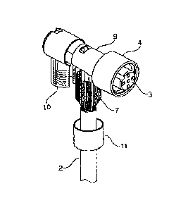
Figure 3 shows the next assembly step in which the assembly prepared in
accordance
with Figure 2 is inserted into an integrally formed shielding shell 10. In
this step, it is
apparent that the shielding braid 7 has been prepared in such a way that it
may be operatively
connected, in particular, electrically connected with the (as seen in Figure
3) downward
pointing end of the shielding shell 10. At the same time, the shielding shell
10 is connected to
the one end of the shielding sleeve 9, the two parts, namely the shielding
sleeve 9 and the
shielding shell 10 forming the complete shield casing 5 (see Figure 1). A
shielding to the
fullest extent possible is achieved as a result of the interaction between the
shielding sleeve 9
and the integrally formed shielding shell 10, seated inside of which is the
prepared assembly.
Such a shielding is achieved primarily because the one end of the integrally
formed shielding
shell 10 is connected to the shielding braid 7, the other end of the
integrally formed shielding
shell 10 being connected to the one end of the shielding sleeve 9. The other
end of the
shielding sleeve 9 points in the direction of the front end of the contact
carrier 3, but does not
extend as far as the front end. In order to also shield the area of the
contact carrier 3 not
9
CA 02854840 2014-05-07
v *
WO 2013/068560
surrounded by the shielding sleeve 9 from high frequencies, the connection
element, here in
particular the knurled nut 4 is present, which coaxially surrounds the contact
carrier 3 while
forming a gap. The gap is adapted and designed to bring the connection element
(in particular
the knurled nut 4) into operative connection with a corresponding connection
element of the
mating plug connector. The complete shielding of such a composite plug
connector,
consisting of plug connector 1 and mating plug connector is thereby achieved.
Also shown in
Figure 3 coaxially surrounding the cable 2 is a crimp sleeve 11 which may but
need not be
present. The crimp sleeve 11 is shown in Figure 3 in its pre-assembly
position. The assembly
and final position thereof will be discussed below.
Figure 4 shows the integrally formed shielding shell 10 once again in its
entirety and
in detail (Detail D). Here it is apparent that the shielding shell 10 has an
opening 12 which is
adapted and designed to accommodate the assembly prepared in accordance with
Figure 2, in
particular the one end of the shielding sleeve 9. Also present is a slot 13,
the slot being
situated in the part of the shielding shell 10 facing away from the opening
12. In this design
the width of the slot 13 is chosen to allow the assembly prepared in
accordance with Figure 2,
in particular the end portion of the cable 2 (or alternatively the area with
the electric leads 6
originating from the end of the cable 2) to be inserted through the slot 13.
It is also apparent
in Figure 4 that the interior portion of the shielding shell 10 intended to be
operatively
connected to the end portion of the shielding sleeve 9 includes at least one
projection 14,
preferably several projections 14 distributed about the circumference. As a
result of these
projections 14, designed preferably as ribs, defined contact points are formed
on the side on
which the opening 12 is located between the surface of the shielding sleeve 9
and the interior
portion of the shielding shell 10 when the shielding sleeve 9 is pressed into
the associated end
of the shielding shell 10. This ensures a high contact reliability for
achieving the continuous
shielding.
CA 02854840 2014-05-07
W02013/068560
Figure 5 shows an implementation of the plug connector 1 in cross-section, in
which
the assembly prepared in accordance with Figure 2 has been inserted into the
shielding shell
10, the shielding sleeve 9 being positionally fixed, for example, pressed,
into the shielding
shell 10. In the lower part, as seen in Figure 5, the shielding shell 10 is
fixed to the cable 2 in
a press fit, more precisely to the shielding braid 7, which is part of the
cable 2. In this variant
the shielding braid 7 is located on the outer surface of the shielding shell
10 and on the
interior portion of the crimp sleeve 11. This means that in this case the
crimp sleeve 11 is
used on the one hand to further seal off the slot 13 (if a gap remains) after
it has been
compressed, and on the other hand to fix the shielding braid 7 in position on
the surface of
the shielding shell 10 and at the same time to electrically contact it. An
alternative variant
would be to feed the end of the cable 2 up to the end of and into shielding
shell 10, so that
then an end portion of the cable sheath of the cable 2 protrudes into the
shielding shell 10.
The advantage of this variant is that, as a result, a strain is also relieved
at the same time.
In the variant shown in Figure 5 in which not the cable 2 directly, but rather
the
shielding braid 7 thereof is fixed to the shielding shell 10 in a press fit,
it is also necessary to
take additional measures in order to achieve a mechanical stability of the
subsequent plug
connector 1. Such mechanical stability may be achieved in a variety of ways.
Figure 6, for
example, shows that the interior portion of the shielding shell 10, up to and
overlapping a
piece of the end portion of the cable 2 is provided with a hot-melt adhesive
15. Such a hot-
melt adhesive 15 has the advantage that on the one hand it fills the remaining
empty spaces in
the shielding shell 10 and thereby forms a media-impermeable bond which
prevents water
and dirt particles and the like from entering between the metal parts in the
interior portion of
the plug connector 1. Moreover, not only is a longitudinal water-tight seal
achieved as a
result of the hot melt adhesive 15, which is also present in the area of the
shielding braid 7
and the end portion of the cable 2 (more precisely the cable sheath), but a
mechanical,
11
A CA 02854840 2014-05-07
W02013/068560
=
preferably initial stability is produced as well. As a rule, namely, the
shielding braid 7 in the
form shown in Figure 5 does not yet have the mechanical stability required for
operating the
plug connector 1. Such stability is achieved only as a result of the hot-melt
adhesive 5, as
shown in Figure 6. In the event the mechanical stability achieved with the hot-
melt adhesive
15 according to Figure 6 is not yet sufficient, or the hot-melt adhesive 15
does not reach
beyond the end portion of the cable 2, it is alternatively or also possible to
provide an
overmolding 16 in accordance with Figure 7. Either such overmolding 16 is
implemented in
such a way that it also extends into the interior of the shielding shell 10
and fills out the latter,
and at the same time forms an exterior housing of the plug connector 1. In
such case, the hot-
melt adhesive 15 may be dispensed with. If, however, the hot-melt adhesive 15
is introduced
in order to produce the longitudinal water-tight seal, the adhesive may also
be especially
advantageously surrounded by the overmolding 16, because it is the hot-melt
adhesive 15 (or
a comparable material which produces a media-impermeable bond between the
materials
involved) which produces the longitudinal water-tight seal, and the mechanical
stability is
only achieved as a result of the overmolding 16 or is enhanced when combined
with the hot-
melt adhesive 15.
Shown in Figures 8 to 13 is a further invention-characterizing embodiment of
the plug
connector 1 according to the invention, the essential elements of which, its
function and the
production thereof are based on the plug connector 1 shown in Figures 1
through 7.
In Figure 8, it is apparent that the shielding shell has an opening 17 in the
upper
cylindrically shaped portion thereof and on the one front end thereof facing
away from the
opening in the direction of the plug face. This opening 17 is situated in a
slightly outwardly
curved elevation in the shielding shell 10. Through this opening 17 a filler
material such as a
hot-melt adhesive or the like may be funneled into the interior of the
shielding shell 10 (and
optionally also into the interior of the shielding sleeve 9). In this design,
the diameter of the
12
CA 02854840 2014-05-07
a
WO 2013/068560
opening 17 is selected so that it is large enough on the one hand to convey
the desired .
quantity of filler material into the interior in a reasonable period of time,
and at the same time
ensure a seal against high frequencies. The diameter of the opening 17
conforms to the
overall diameter of the cylindrically shaped part of the shielding shell 10
and is significantly
smaller than the former. The shielding shell 10 also includes two opposing
indentations 18
present below the longitudinal axis of the cylindrically shaped part of the
shielding shell 10.
Also present in the shielding shell 10 is a catch 19 which is situated in the
area of an opening
20. The catch 19 enables the shielding shell 10 to be latched to the shielding
sleeve 9 (see
Figure 9). For this purpose, the shielding sleeve 9 includes a recess 21,
whereby the edges of
the recess 21 come into contact with the indentations 18 of the shielding
shell 10 when the
shielding sleeve 9 is inserted coaxially into the shielding shell 10. In the
process, the catch 19
and an opening 22 in the shielding sleeve 9 are operatively connected, as a
result of which the
shielding sleeve 9 is fixedly latched to the shielding shell 10. This stage of
assembly is shown
in Figures 10 and 11. While Figure 10 shows that the interior of the shielding
sleeve 9 and of
the shielding shell 10 are not yet filled with a filler material (but may be
filled), Figure 11,
left view, shows that the interior and/or the exterior of shielding sleeve 9
and shielding shell
are filled with and/or surrounded by the overmolding 16. Shown in the right
hand view of
Figure 11 is a ring 23 which may, but need not be present. This ring 23 may
also be formed
by a hot-melt adhesive, an overmolding or the like, and surrounds the elements
situated
within it, for example, the contact carrier 3, the mating contact elements 8
and the like in
order to produce a longitudinal water-tight seal. Finally, Figure 12 shows a
cross-section of
the completed plug connector 1, the overmolding 16 being surrounded by an
additional
overmolding 24 which forms a casing. The hot-melt adhesive 15, the overmolding
16 and the
overmolding 24 may be produced in successive process steps and may be made of
the same
or of different materials. It should be mentioned here that not all three
materials have to be
13
= = , CA 02854840 2014-05-07
= W020131068560
used, but rather, as the case may be, it is sufficient to provide only the
overmolding 16 which
forms the casing or the overmolding 24 (for example, in such case without the
hot-melt
adhesive 15).
Figure 13 shows once again in detail the embodiment of the shielding shell 10
according to Figure 4 or according to Figure 8. In this case, the shielding
shell 10 either has
no opening or simply the opening 17. In both variants, an indentation 18 is
present in each
case for positionally fixing the shielding sleeve 9 in the shielding shell 10,
two indentations
18 being situated opposite one another in the shielding shell 10. The plane in
which the two
indentations 18 are situated, is located outside a plane which extends through
the longitudinal
axis of the cylindrically shaped upper part of the shielding shell 10 and the
shielding sleeve 9.
This ensures that the shielding sleeve 9 comes to rest with its longitudinal
edges of recess 21
against the two indentations 18, in order to be arranged twist-proof in the
shielding shell.
Other designs are also conceivable with which the shielding sleeve may be
mounted twist-
proof in the shielding shell 10. Finally, apparent in Figure 13 is the detail
that the downward
pointing portion of the shielding shell 10 includes a surface elevation, i.e.
in the area of the
slot 13. This surface design, preferably elevations and depressions pointing
in a downward,
axial direction, ensures that a larger surface and with that a greater contact
reliability is
achieved for the shielding braid 7.
The upper part of Figure 14 shows a finished plug connector 1 in a three-
dimensional
view. In the lower left representation the plug connector 1 is shown with a
view of its plug
face and in the lower right representation it may again be seen in a sectional
view.
The following may be noted with regard to the attachment of the shielding
braid 7 to
the downward pointing cylindrically shaped part of the shielding shell as seen
in the figures.
For one, the shielding braid 7 may be situated within the cylindrically shaped
part of the
shielding shell 9. In such case, it is conceivable for the electric leads 6 to
be surrounded by a
14
= == CA 02854840 2014-05-07
W02013/068560
common sheath, which in turn is surrounded by the shielding braid 7. In this
case, the
shielding braid 7 may be supported either on the electric leads 6 (once the
sheath has been
removed) and/or on the sheath of the cable 2 if the cylindrically shaped part
of the shielding
shell 10 is situated over it and then fixed in a press fit. This presupposes
that the shielding
shell 10 is designed in such a way and made of such a material that it may be
pressed
together, thereby narrowing the slot 13. In addition or alternatively, it is
conceivable to
arrange the entire shielding braid 7 on the outer surface of the downward
pointing,
cylindrically shaped end portion of the shielding shell 10, or partially
inside and partially
outside it. The arrangement of the shielding braid 7, more precisely the end
thereof, on the
outer surface of the lower end portion of the shielding shell 10 is especially
preferred. In this
configuration, the shielding shell 10 is designed and made of such a material
that when the
shielding braid is fixed on the shielding shell 10 in a press fit, the
shielding shell is not
deformed (or only negligibly deformed) when pressing against the shielding
braid or when
sliding and crimping the crimp sleeve 11 together, such that the shielding
shell 10 offers a
stable counteracting force for achieving the press fit. Alternatively or in
addition to the press
fit, it is conceivable to fix and to electrically contact the shielding braid
7 inside and/or
outside the shielding shell 10 using other methods and/or means. Here,
welding, caulking,
adhering (with an electrically conductive adhesive) or the like may be
considered.
= CA 02854840 2014-05-07
W02013/068560
List of reference numerals:
1. plug connector
2. cable
3. contact carrier
4. knurled nut
5. shield casing
6. electric leads
7. shielding braid
8. mating contact elements
9. shielding sleeve
10. shielding shell
11. crimp sleeve
12. opening
13. slot
14. projection
15. hot-melt adhesive
16. overrnolding
17. opening
18. indentation
19. catch
20. opening
21. recess
22. opening
23. ring
16
CA 02854840 2014-05-07
WO 2013/068560
=
24. overmolding
25. seal
17