Note: Descriptions are shown in the official language in which they were submitted.
CA 02854869 2014-05-07
WO 2013/070566 PCT/US2012/063641
- 1 -
PRODUCTION OF LOW CLOUD POINT DISTILLATES
FIELD OF THE INVENTION
100011 This invention provides methods for multi-stage hydroprocessing to
form low
cloud point distillates.
BACKGROUND OF THE INVENTION
100021 The equipment necessary for refining operations is one of the major
sources
of costs in a refinery. The equipment can include catalytic reactors,
fractionators and/or
separators, and other supporting equipment. In a conventional process train,
each
catalytic reactor can have a dedicated fraction.ator or separator associated
with the
reactor, to separate out the various products produced in the catalytic
reaction stage.
[00031 In diesel hydroprocessing, it is sometimes beneficial to include a
dewaxing
stage as part of reaction train in order to improve properties of the
resulting diesel fuel
such as pour point or cloud point. For feeds with suitably low levels of
sulfur and/or
nitrogen, the &waxing stage can be included as part of a reactor that contains
a
hydrotreatin.g stage. Feeds with higher levels of sulfur and/or nitrogen,
however, may
benefit from having a separate reactor for the &waxing stage. This leads to a
further
increase in the capital costs necessary for generating a diesel fuel product.
[09041 U.S. Patent 3,431,194 describes a process for lowering the pour
point of a
middle distillate feed. The middle distillate is split into a lower boiling
fraction and a
higher boiling fraction. The higher boiling fraction is hydroisomerized to
reduce the
cloud point and pour point of the higher boiling fraction. The higher boiling
fraction is
then recombined with the lower boiling fraction to form a middle distillate
with
improved pour point and cloud point relative to the original feed. Based on
the
examples, it appears that the cut point for the lower boiling fraction is
selected so that the
cloud point of the lower fraction is lower than the cloud point for the
hydroisomerized
higher boiling fraction.
CA 02854869 2014-05-07
WO 2013/070566 PCT/US2012/063641
-2 -
[0005] U.S. Patent 3,412,016 shows an example of a fractionator that
includes
multiple volumes. In U.S. Patent 3,412,016, two independent refinery gasoline
streams
(such as a low octane and a high octane gasoline) are fractionated in the
fractionator.
The outputs from the fractionator are a light fraction and distinct heavy
fractions from
the two separate volumes in the fractionator. In the fractionator, the lighter
portions of
the two gasoline fractions are allowed to mix.
[0006] European patent publication EP 0819752 appears to provide another
example
of using a fractionator having multiple volumes. In EP 0819752, it appears
that two
separate input streams are provided to the fractionator. The vapor portions
produced in
each side of the fractionator are allowed to mix, leading to production of one
or more
light product fractions from the fractionator. Each side of the fractionator
also produces
a bottoms portion. In some figures, the bottom portions appear to remain
separated after
leaving the fractionator, while in other figures the input to the second side
of the
fractionator includes portions of the bottoms from both sides of the
fractionator.
[0007] U.S. Published Patent Application 2001/0132803 describes a two-stage
hydroprocessing system that includes a divided wall column fractionator.
Methods are
described for using the hydroprocessing system to generate a plurality of
distillate
boiling range products from the divided volumes in the fractionator.
Additionally, a
naphtha and/or a kerosene product are generated from a common volume at the
top of the
fractionator.
SUMMARY OF THE INVENTION
[0008] In an embodiment, a method for producing distillate products is
provided.
The method includes hydrotreating a feedstock under effective hydrotreating
conditions;
passing at least a portion of the hydrotreated feedstock into a first separate
volume of a
divided wall fractionator; fractionating the at least a portion of the
hydrotreated feedstock
to form a heavy diesel fraction and a first light diesel fraction, the heavy
diesel fraction
being withdrawn from the first separate volume of the divided wall
fractionator;
&waxing the heavy diesel fraction under effective dewaxing conditions to
produce a
CA 02854869 2014-05-07
WO 2013/070566 PCT/US2012/063641
- 3 -
dewaxed heavy diesel fraction having a cloud point of about -10'C or less;
passing the
dewaxed heavy diesel fraction into a second separate volume of the divided
wall
fractionator; and fractionating the dewaxed heavy diesel fraction to form at
least a heavy
diesel product withdrawn from the second separate volume, the fractionation
further
producing a second light diesel fraction, wherein the first light diesel
fraction and the
second light diesel fraction form a combined light diesel fraction that is
withdrawn from
a common volume of the divided wall fractionator.
10009] in another embodiment, a method for producing distillate products is
provided. The method includes hydrotreating a feedstock under effective
hydrotreating
conditions; fractionating at least a portion of the hydrotreated feedstock to
form a heavy
diesel fraction and a light diesel fraction; dewaxing the heavy diesel
fraction under
effective dewaxing conditions to produce a dewaxed heavy diesel fraction
having a cloud
point of about -10 C or less; fractionating the dewaxed heavy diesel fraction
to form a
dewaxed diesel product and at least one of a naphtha fraction or a light ends
fraction; and
combining at least a portion of the dewaxed diesel product and the light
diesel fraction to
form a combined diesel product, the combined diesel product having
substantially the
same cloud point as the dewaxed diesel product and the light diesel fraction.
BRIEF DESCRIPTION OF THE FIGURES
[0010] FIGURE 1 schematically shows a reaction system for performing a
process
according to an embodiment of the invention.
[0011] FIGURE 2 shows an alternate embodiment reaction system for
performing a
process according to an embodiment of the invention.
100121 FIGURES 3, 4, 5, & 6 show simulated results from processing feeds
according to an embodiment of the invention.
CA 02854869 2014-05-07
WO 2013/070566 PCT/US2012/063641
- 4 --
DETAILED DESCRIPTION OF THE EMBODIMENTS
Overview
[0013] In various embodiments, systems and methods are provided for
producing at
least one low sulfur distillate fuel product with improved low temperature
properties. A
potential distillate fuel feed is initially hydrotreated to reduce sulfur and
nitrogen levels
in the feed to desired amounts. In some embodiments, the distillate fuel feed
will be a
feed with a nitrogen content of at least about 500 ppmw. The hydrotreated
effluent is
then fractionated to form several fractions, including a light
diesel/distillate fraction and
a heavy diesel fraction. The heavy diesel fraction is then dewaxed to improve
the cold
flow properties of the heavy diesel fraction. The dewaxed heavy diesel
fraction can be
combined with the light diesel fraction, or the dewaxed heavy diesel fraction
can be
fractionated as well. Preferably, the heavy diesel fraction is dewaxed under
conditions
effective for producing a dewaxed fraction with a cloud point that is less
than or equal to
the cloud point of the light diesel/distillate fraction.
[0014] In some embodiments, a further advantage may be gained by using a
divided
wall column fractionator in place of having separate fractionators for each
stage of the
process. In such embodiments, the effluent from the hydrotreatm.ent stage(s)
is passed
into a first separate volume of a divided wall fractionator. A height for the
dividing wall
is selected so that a light diesel fraction is withdrawn from the upper,
common volume of
the fractionator. One or more heavier fractions, including a heavy diesel
fraction, are
withdrawn from the first separate volume. Optionally, the heavy diesel
fraction can
correspond to a bottoms fraction from the first separate volume. At least a
portion of the
heavy diesel fraction is then passed into a reactor containing one or more
&waxing
stages. The effluent from the dewaxi.ng stage(s) is returned to a second
separate volume
of the divided wall fractionator. Any light diesel (or lighter molecules)
generated during
dewaxing are again withdrawn from. the common volume of the fractionator. A
heavy
diesel product stream is withdrawn from the second separate volume.
CA 02854869 2014-05-07
WO 2013/070566 PCT/US2012/063641
- 5 -
[0015] In a preferred embodiment where a divided wall column fractionator
is used,
the light diesel fraction is withdrawn from the common volume of the
fractionator. This
means that the light diesel fraction includes molecules that have passed only
through the
hydrotreating stage as well as molecules that have passed through the dewaxing
stage.
For the molecules that have passed through the dewaxing stage and are included
in the
light diesel fraction, at least a portion of the molecules will correspond to
molecules that
boiled below the light diesel cut point due to isomerization. For example, one
option for
the light diesel versus heavy diesel cut point is about 285 C. The boiling
point for
n-hexadecane (C161-134, also referred to as cetane) is about 287 C. In the
hydrotreating
effluent, most of the n-hexadecane would be expected to form part of the heavy
diesel
fraction if the cut point is 285 C. After dewaxing, some of the n-hexadecane
molecules
will isomerize to form. alkanes with one or more methyl side groups, such as
2,3-dimethyl tetradecane. Such a compound would be expected to have a boiling
point
somewhere between 260 C and 280 C, and therefore would be expected to form
part of
the light diesel fraction.
[0016] The addition of isomerized molecules to the light diesel fraction is
valuable
for the cetane rating of the light fraction. Cetane rating generally increases
with
molecular weight for a given type of compound. However, increasing the
branching for
compounds with similar numbers of carbon atoms tends to reduce the cetane
rating of a
compound. The compound n-hexadecane has a cetane rating of 100. By contrast,
an
isomerized version of n-hexadecane to have one or more branches with methyl
groups
would be expected to have a cetane rating of 55 or 60.
100171 Light diesel fractions (or jet fuel fractions) typically have lower
cetane ratings
than heavy diesel fractions due to the lower molecular weight of the average
component.
A typical light diesel fraction or jet fuel fraction may only have a cetane
rating of 40-45.
Even though an isomerized C16 molecule has a lower cetane rating than the n-
alkane
version, the cetane value of the isomerized C16 molecule will typically be
higher than the
cetane rating for a light diesel fraction. A similar situation will occur for
other cut points
in the range of about 250 C to about 370 C. In embodiments where the diesel
dewaxing
is performed using a dewaxing catalyst that operates primarily by
isomerization, the
CA 02854869 2014-05-07
WO 2013/070566 PCT/US2012/063641
- 6 -
portion of the light diesel fraction (or jet fuel fraction) formed during
dewaxing is
believed to enhance the cetane of the overall light diesel fraction (or jet
fuel fraction).
This improvement to the light diesel fraction can be achieved without having
to perform
a separate fractionation on the output from. the dewaxing stages. Instead, the
light diesel
fraction withdrawn from the common volume of the divided wall fracrionator
includes
both the light diesel from. the hydrotreating stage and the light diesel from
the dewaxing
stage.
1001811 Still another potential advantage is reducing saturation of
aromatics in a light
diesel fraction. Saturation of aromatic compounds to corresponding cycloalkyl
compounds typically provides only a modest cetane benefit. However, aromatic
saturation processes can consume a substantial amount of hydrogen. By
separating out
the light diesel fraction before dewaxing, additional aromatic saturation on
compounds in
the light diesel fraction is avoided. Additionally, aromatics in a diesel fuel
contribute to
the lubricity of the fuel. Saturation of the aromatics in a light diesel
fraction may reduce
the lubricity to below a desirable value in some applications. Separating out
the light
diesel fraction before dewaxing preserves the aromatics present in the light
diesel
fraction.
Feedstocks
[0019] In an embodiment, a feedstock can have an initial boiling point of
at least
about 200 F (93 C), or at least about 250 F (121"C), or at least about 300 F
(149 C), or
at least about 350 F (177 C), or at least about 400 F (204 C), or at least
about 450 F
(232"C). The initial boiling can vary widely, depending on how much kerosene
or other
lighter distillate components are included in a feedstock. In another
embodiment, the
feedstock can have a final boiling point of about 800 F (427 C) or less, or
about 750 F
(399 C) or less, or about 700 F (371 C) or less. Alternatively, in embodiments
where
fractionation is used to produce both a heavy diesel fraction and a separate
bottoms
fraction, the final boiling point can be about 1100 F (593 C) or less, or
about 1000 F
(538 C) or less, or about 900 F (482 C) or less. Another way of characterizing
a
feedstock is based on the boiling point required to boil a specified
percentage of the feed.
CA 02854869 2014-05-07
WO 2013/070566
PCT/US2012/063641
- 7 -
For example, the temperature required to boil at least 5 wt% of a feed is
referred to as a
"T5" boiling point. When characterizing a feed based on a T5 boiling point,
the
feedstock can have a T5 boiling point at least about 200 F (93 C), or at least
about
250 F (121 C), or at least about 300 F (149 C), or at least about 350 F (177
C), or at
least about 400 F (204 C), or at least about 450 F (232 C). In another
embodiment, the
feed can have a195 boiling point of about 800 F (427 C) or less, or about 750
F
(399 C) or less, or about 700 F (371 C) or less. Examples of suitable feeds
include
various atmospheric and/or vacuum gas oil feeds, diesel boiling range feeds,
and feeds
corresponding to mixtures thereof.
[0020] In some embodiments, the feedstock generally comprises a mineral
oil. By
"mineral oil" is meant a fossil/mineral fuel source, such as crude oil, and
not the
commercial organic product, such as sold under the CAS number 8020-83-5, e.g.,
by
Aldrich. Examples of mineral oils can include, but are not limited to,
straight run
(atmospheric) gas oils, vacuum gas oils, demetallized oils, coker distillates,
cat cracker
distillates, heavy naphthas, diesel boiling range distillate fraction, jet
fuel boiling range
distillate fraction, kerosene boiling range distillate fraction, and coal
liquids. The
mineral oil portion of the feedstock can comprise any one of these example
streams or
any combination thereof Preferably, the feedstock does not contain any
appreciable
asphaltenes.
[0021] Mineral feedstreams suitable for use in various embodiments can have
a
nitrogen content from about 10 wppm to about 6000 wppm nitrogen, such as at
least
about 50 wppm, and preferably at least about 500 wppm, such as at least about
750
wppm or at least about 1000 wppm or at least about 1500 wppm. Although
feedstreams
with lower nitrogen contents can be processed in a two stage reaction system,
one of the
benefits of having the hydrotreating and dewaxing reactions occur in separate
stages is
the opportunity to remove gas phase nitrogen contaminants between the stages.
The
NH3 generated from hydrotreatrnent of a feed with less than 500 wppm of
nitrogen can
often be managed in a reaction system without a gas phase separation between
hydrotreating and devvaxing stages. In an embodiment, feedstreams suitable for
use
herein have a sulfur content from about 100 wppm to about 40,000 wppm sulfur,
CA 02854869 2014-05-07
WO 2013/070566 PCT/US2012/063641
- 8 -
preferably about 200 wppm to about 30,000 wppm, and more preferably about 350
wppm to about 25,000 wppm.
[0022] In various embodiments of the invention, the feed can also include
portions of
the feed that are from biocomponent sources. The feed can include varying
amounts of
feedstreams based on biocomponent sources, such as vegetable oils, animal
fats, fish
oils, algae oils, etc. For a biocomponent feed that has been previously
hydroprocessed or
that is otherwise compatible with conventional refinery equipment, the feed
could
potentially be entirely derived from a biocomponent source. More typically,
the feed can
include at least 0.1 wt% of feed based on a biocomponent source, or at least
0.5 wt%, or
at least 1 wt%, or at least 3 wt%, or at least 10 wt%, or at least 15 wt%. in
such
embodiments, the feed can include 90 wt% or less of a feed based on a
biocomponent
source, or 60 wt% or less, or 40 wt% or less, or 20 wt% or less. In other
embodiments,
the amount of co-processing can be small, with a feed that includes at least
0.5 wt% of
feedstock based on a biocomponent source, or at least 1 wt%, or at least 2.5
wt%, or at
least 5 wt%. In such an embodiment, the feed can include 20 wt% or less of
biocomponent based feedstock, or 15 wt% or less, or 10 wt% or less, or 5 wt%
or less.
[0023] In the discussion below, a biocomponent feed or feedstock refers to
a
hydrocarbon feedstock derived from. a biological raw material component, such
as
vegetable fats/oils or animal fats/oils, fish oils, pyrolysis oils, and algae
lipids/oils, as
well as components of such materials, and in some embodiments can specifically
include
one or more types of lipid compounds. A biocomponent portion of a feed can be
a
portion that has been previously hydroprocessed, a portion that has not been
previously
hydroprocessed, or a combination thereof.
10024] Lipid compounds are typically biological compounds that are
insoluble in
water, but soluble in nonpolar (or fat) solvents. Non-limiting examples of
such solvents
include alcohols, ethers, chloroform, alkyl acetates, benzene, and
combinations thereof
Major classes of lipids include, but are not necessarily limited to, fatty
acids, glycerol-
derived lipids (including fats, oils and phosphol.ipids), sphin.gosine-derived
lipids
(including cerami.des, cerebrosides, gangliosides, and sphingomyel.in.$),
steroids and their
CA 02854869 2014-05-07
WO 2013/070566
PCT/US2012/063641
- 9 -
derivatives, terpenes and their derivatives, fat-soluble vitamins, certain
aromatic
compounds, and long-chain alcohols and waxes. In living organisms, lipids
generally
serve as the basis for cell membranes and as a form of fuel storage. Lipids
can also be
found conjugated with proteins or carbohydrates, such as in the form of
lipoproteins and
lipopolysaccharides.
[0025] Examples of vegetable oils that can be used in accordance with this
invention
include, but are not limited to rapeseed (canola) oil, soybean oil, coconut
oil, sunflower
oil, palm oil, palm. kernel oil, peanut oil, linseed oil, tall oil, corn oil,
castor oil, jatropha
oil, jojoba oil, olive oil, flaxseed oil, camelina oil, safflower oil, babassu
oil, tallow oil
and rice bran oil.
[00261 Vegetable oils as referred to herein can also include processed
vegetable oil
material. Non-limiting examples of processed vegetable oil material include
fatty acids
and fatty acid alkyl esters. Alkyl esters typically include CI -05 alkyl
esters. One or
more of methyl, ethyl, and propyl esters are preferred.
[0027] Examples of animal fats that can be used in accordance with the
invention
include, but are not limited to, beef fat (tallow), hog fat (lard), turkey
fat, fish fat/oil, and
chicken fat. The animal fats can be obtained from. any suitable source
including
restaurants and meat production facilities.
[0028] Animal fats as referred to herein also include processed animal fat
material.
Non-limiting examples of processed animal fat material include fatty acids and
fatty acid
alkyl esters. Alkyl esters typically include CI -05 alkyl esters. One or more
of methyl,
ethyl, and propyl esters are preferred.
10029] Algae oils or lipids can typically be contained in algae in the form
of
membrane components, storage products, and/or metabolites. Certain algal
strains,
particularly microalgae such as diatoms and cyanobacteria, can contain
proportionally
high levels of lipids. Algal sources for the algae oils can contain varying
amounts, e.g.,
from. 2 wt% to 40 wt% of lipids, based on total weight of the biomass itself.
CA 02859869 2014-05-07
WO 2013/070566 PCT/US2012/063641
- 10..
[0030] Algal sources for algae oils can include, but are not limited to,
unicellular and
multicellular algae. Examples of such algae can include a rhodophyte,
chlorophyte,
heterokontophyte, tribophyte, glaucophyte, chlorarachniophyte, euglenoid,
haptophyte,
cryptomonad, dinoflagellum, ph.ytoplankton, and the like, and combinations
thereof. In
one embodiment, algae can be of the classes Chlorophyceae and/or Haptophyta.
Specific
species can include, but are not limited to, Neochloris oleoabundans,
Scenedesmus
dimorphus, Euglena gracilis, Phaeodactylunz tricornutwn, Pleurochrysis
carterae,
Prymnesiwn parvum, Tetraselmis chui, and Chlamydomonas reinhardtii. Additional
or
alternate algal sources can include one or more microalgae of the Achnanthes,
Amphiprora, Amphora, Ankistrodesmus, Asteromonas, .Boekelovia, Borodinella,
Botryococcus, Bracteococcus, Chaetoceros, Carteria, Chlamydomonas,
Chlorococcum,
Chlorogonium, Chlorella, Chroomonas, Chrysosphaera, Cricosphaera,
Crypthecodinium, Cr)ptomonas, Cyclotella, Dunaliella, Ellipsoidon, Emiliania,
Eremos:phaera, Ernodesmius, Euglena, Franceia, Fragilaria, Gloeothamnion,
Haematococcus, Halocafeteria, Hymenomonas, kochrysis, Lepocinclis,
Micractinium,
Monoraphidiunt, Nannochloris, Nannochloropsis, Navicula, Neochloris,
Nephrochloris,
Nephrosehnis, Nitzschia, Ochromonas, Oedogonium, Oocystis, Ostreococcus,
Pavlova,
Parachlorella, Pascheria, Phaeodactylum, Phagus, Platymonas, Pleurochzysis,
Pleurococcus, Prototheca, Pseudochlorella, Pyramintonas, Pyrobottys,
Scenedesmus,
Skeletonenza, Spyrovra, Stichococctts, Tetraselmis, Thalassiosira, Viridiella,
and
Vo/vox species, and/or one or more cyanobacteria of the Agmenellum, Anabaena,
Anabaenopsis, Anacystis, Aphanizomenon, Arthrospira, Asterocapsa, Borzia,
Calothrix,
Chamaesiphon, Chlorogloeopsis, Chroococcidiopsis, Chroococcus, Crinalium,
Cyanobacterium, Cyanobium, Cyanocystis, Cyanospira, C'yanothece,
Cylindrospermopsis, Cylindrospermunt, Dactylococcopsis, Dermocarpella,
Fischerella,
Fremyella, Geitleria, Geitlerinema, Gloeobacter, Gloeocapsa, Gloeothece,
Halospirulina, Iyengariella, Leptolyngbya, Limnothrix, Lyngbya, Microcoleus,
Microcystis, Atvxosarcina, Nodularia, Nostoc, iVostochopsis, Oscillatoria,
Phormidium,
Planktothrix, Pleurocapsa, Prochlorococcus, Prochloron, Prochlorothrix,
Pseudanabaena, Rivularia, Schizothrix, Scytonema, Spirulina, Stanieria,
Starria,
Stigonema, Synzploca, Synechococcus, Synechocystis, Tol,vpothrix,
Trichodesmium,
7),chonema, and Xenococcus species.
CA 02859869 2014-05-07
WO 2013/070566 PCT/US2012/063641
- 11 -
[0031.] Other biocomponent feeds usable in the present invention can
include any of
those which comprise primarily triglycerides and free fatty acids (FFAs). The
triglycerides and FFAs typically contain aliphatic hydrocarbon chains in their
structure
having from 8 to 36 carbons, preferably from 10 to 26 carbons, for example
from 14 to
22 carbons. Types of triglycerides can be determined according to their fatty
acid
constituents. The fatty acid constituents can be readily determined using Gas
Chromatogaphy (GC) analysis. This analysis involves extracting the fat or oil,
saponifying (hydrolyzing) the fat or oil, preparing an alkyl (e.g., methyl)
ester of the
saponified fat or oil, and determining the type of (methyl) ester using GC
analysis. In
one embodiment, a majority (i.e., greater than 50%) of the triglyceride
present in the
lipid material can be comprised of C io to C26 fatty acid constituents, based
on total
triglyceride present in the lipid material. Further, a triglyceride is a
molecule having a
structure identical to the reaction product of glycerol and three fatty acids.
Thus,
although a triglyceride is described herein as being comprised of fatty acids,
it should be
understood that the fatty acid component does not necessarily contain a
carboxylic acid
hydrogen. In one embodiment, a majority of triglycerides present in the
biocomponent
feed can preferably be comprised of C12 to C18 fatty acid constituents, based
on total
triglyceride content. Other types of feed that are derived from biological raw
material
components can include fatty acid esters, such as fatty acid alkyl esters
(e.g., FAME
and/or FAEE).
10032] in some embodiments, a feed containing a biocomponent portion will
include
previously hydroprocessed biocomponent portions. Biocomponent feeds that are
previously hydroprocessed will typically have reduced levels of heteroatoms
such as
oxygen or nitrogen. Such previously hydroprocessed biocomponent feeds can be
used in
small quantities, such as at least and possibly could be used as the entire
feed.
[0033] In other embodiments, the biocomponent portion of the feedstock
(such as the
glycerides and/or fatty acid esters) can include a non-hydrotreated portion. A
non-
hydrotreated feed can typically have an olefin content and an oxygen content
similar to
the content of the corresponding raw biocomponent material. Examples of
suitable
biocomponent feeds can include food grade vegetable oils, and biocomponent
feeds that
CA 02859869 2014-05-07
WO 2013/070566 PCT/US2012/063641
- 12 -
are refined, bleached, and/or deodorized. Other suitable biocomponent feeds
include
feeds derived from an algae source.
[0034] In some embodiments where a biocomponent portion is included in the
feed,
the feedstock can include at least about 1% by weight of glycerides, lipids,
fatty acids,
fatty acid esters (such as fatty acid alkyl esters), or a combination thereof.
The
gylcerides can include monoglycerides, diglycerides, or triglycerides. In
other
embodiments, the feedstock can include at least about 5 wt%, or at least about
10 wt%,
or at least 20 wt% of glycerides, lipids, fatty acids, fatty acid esters,
fatty acid alkyl
esters, or a combination thereof. Alternatively, the feedstock can include
about 55 wt%
or less, or about 35 wt% or less, or about 25 wt% or less, or about 20 wt% or
less of
glycerides, lipids, fatty acids, fatty acid esters, fatty acid alkyl esters,
or a combination
thereof. In an embodiment, the feedstock can include glycerides and/or fatty
acid esters.
Preferably, when the feedstock includes a biocomponent portion, the feedstock
can
include triglycerides, fatty acid methyl esters, or a combination thereof.
[0035] Biocomponent based diesel boiling range feedstreams can have a wide
range
of nitrogen and/or sulfur contents. For example, a biocomponent based
feedstream based
on a vegetable oil source can contain up to about 300 wppm nitrogen. In
contrast, a
biomass based feedstream containing whole or ruptured algae can sometimes
include a
higher nitrogen content. Depending on the type of algae, the nitrogen content
of an algae
based feedstream can be at least about 2 wt%, for example at least about 3
wt%, at least
about 5 wt%, or at least about 10 wt%, and algae with still higher nitrogen
contents are
known. The sulfur content of a biocomponent feed can also vary. In some
embodiments, the sulfur content can be about 500 wppm or less, for example
about 100
wppm or less, about 50 wppm or less, or about 10 wppm or less.
[0036] Aside from nitrogen and sulfur, oxygen can be another heteroatom
component in biocomponent based feeds. A biocomponent diesel boiling range
feedstream based on a vegetable oil, prior to hydrotreatment, can include up
to about 10
wt% oxygen, or up to about 12 wt%, or up to about 14 wt%. Additionally or
alternately,
such a biocomponent diesel boiling range feedstream can include at least about
1 wt%
CA 02859869 2014-05-07
WO 2013/070566 PCT/US2012/063641
- 13 -
oxygen, for example at least about 2 wt%, at least about 3 wt%, at least about
4 wt%, at
least about 5 wt%, at least about 6 wt%, or at least about 8 wt%. Further
additionally or
alternately, a biocomponent feedstream, prior to hydrotreatment, can include
an olefin
content of at least about 3 wt%, for example at least about 5 wt% or at least
about 10
wt%.
Divided Wall Column as a Fractionator
100371 In various embodiments, a divided wall column can be employed as a
fractionation tower. The divided wall column can contain at least three
separate
volumes. One of the volumes is a common volume toward the top of the divided
wall
column. The remaining volumes in the divided wall column represent volumes
separated
from each other by a dividing wall. The various volumes are all in fluid
communication
via the common volume. However, petroleum fractions with a sufficiently high
boiling
point will not travel up the column to a sufficient height to reach the common
volume.
[00381 In various embodiments below, the divided wall column will be
described as
having one common volume and two separated volumes. However, a divided wall
column could also have three or more separated volumes.
100391 The volumes can be arranged in any configuration that is convenient
for the
desired fractionations. One option is to have each of the separated volumes
occupy equal
portions of the divided section. For example, a divided wali column with two
separated
area and one common area above could have each of the separated areas occupy
half of
the lower portion of the divided wall column. Similarly, a divided wall column
with
three separated areas could have each separated area occupy a third of the
lower portion.
Alternatively, each of the separated areas can have a different volume.
[0040] In various embodiments, the position of the dividing wall can be any
convenient position that leads to the appropriate vol.um.es for the separated
areas. For a
divided wall column having a roughly round cylindrical shape, one option is to
have a
dividing wall that corresponds to a diameter of the column. This would produce
two
CA 02859869 2014-05-07
WO 2013/070566 PCT/US2012/063641
- 14 -
separated areas with equal volumes. Another option is to have a dividing wall
that
corresponds to a chord connecting two points on the circumference of the round
shape,
thus leading to different volumes for each separated volume. Still another
option would
be to have a dividing wall that creates concentric circular volumes for the
separated
portions. While it is believed that roughly round cylindrical shapes are
preferred for the
external shell of divided wall columns, the above placements for a dividing
wall can be
equally applied to columns having other shapes.
100411 In an embodiment, the dividing wall can have a height that is tall
enough to
allow for removal of at least one fraction from a separated volume within the
column.
This m.eans that at least one fraction that does not mix with the common
volume can be
removed from a separated area. Additionally, the dividing wall can have a
height that is
low enough so that at least two fractions can be removed from the common
volume, and
preferably at least three fractions. For example, a common volume can be used
to
produce at least a naphtha fraction and a light diesel fraction, while heavier
diesel
fractions are removed from the separated volumes. If the fractionator is also
used to
separate out gas phase components such as light ends and contaminants (FI2S,
NH3), the
gas phase components can be viewed as a third fraction that is removed from
the
common volume. Still other optional fractions can also be removed, such as by
removing a separate kerosene fraction, multiple light diesel fractions, or
multiple naphtha
fractions.
100421 Alternatively, the height of the dividing wall can be selected based
on the
location of a condensing zone in the column. For a given product produced by a
distillation column, the condensing zone or stage for the product represents
an upper
limit for the expected height of travel for vapor of the given product. For
the example of
preventing contamination between diesel fractions, selecting a dividing wall
height
corresponding to the condensing zone for a diesel fraction would be expected
to limit
contamination to about 1 wt% or less, or about 0.1 wt% or less, or about 0.05
wt% or
less.
CA 02859869 2014-05-07
WO 2013/070566 PCT/US2012/063641
- 15 -
[0043] In still another embodiment, the height of the dividing wall can be
selected in
relation to one or more features of the divided wall column. For example, the
height of
the dividing wall can be selected to correspond to about the height between
the bottom of
the column and the height of the flash zone. In another embodiment, the height
of the
dividing wall can correspond to the height of the bottom section of trays in
the column.
[0044] In yet another embodiment, the height of the dividing wall can be at
least
about 15% of the height of the divided wall column, or at least about 25%, or
at least
about 30%. Alternatively, the height of the dividing wall can be about 50% or
less of the
height of the divided wall column, or about 40% or less, or about 30% or less.
The
height of the divided wall column can be about 25 meters or less, or about 35
meters or
less, or about 50 meters or less, or about 75 meters or less, or about 100
meters or less.
[0045] The diameter of a divided wall column can be selected so that the
cross-sectional areas of the separate volumes roughly correspond to the cross-
sectional
areas of the individual fractionation columns that are being replaced. In an
embodiment,
the cross-sectional areas of the separate volumes can be within about 10% or
less of the
cross-sectional areas of the individual fractionation columns being replaced,
or within
about 5% or less.
[0046] In an embodiment, the interior of the divided wall column can
include typical
components of a fractionator. For example, a series of trays can be located in
the divided
wall column to assist with fractionation. Some of the trays can be located in
the common
volume. Other trays can be located in the separate volumes. The tray locations
and/or
spacing in the separate volumes can be the same or different in each volume.
As an
alternative to trays, any other type of internal structure typically found in
a fractionator
can be used, such as random packings, structured packi.ngs, grids, liquid and
vapor
distributors, and liquid and vapor collectors. The divided wall column can
also include
other typical fractionator parts, such as a flash zone or a sump.
CA 02854869 2014-05-07
WO 2013/070566 PCT/US2012/063641
16
I-Ivdrotreatment
[0047] In an embodiment, the reaction system can include the following
features.
The feed.stock is first treated in a hydrotreatment reactor including one or
more
hydrotreatment stages or beds. The reaction conditions in a hydrotreatment
stage can be
conditions suitable for reducing the sulfur content of the feedstream, The
reaction
conditions can include an LEW of 0.3 to 5.0 hr--, a total pressure from about
500 psig
(3.4 MPa) to about 3000 psig (20.7 MPa), a treat gas containing at least about
80%
hydrogen (remainder inert gas), and a temperature of from about 500 F (260 C)
to about
800 F (427 C). Preferably, the reaction conditions include an LHSV of from
about 0.5
to about 1.5 hr-1, a total pressure from about 1400 psig (9.7 MPa) to about
2000 psig
(13.8 MPa), and a temperature of from about 700 F (371 C) to about 750 F (399
C).
[0048] Optionally, the stages in the hydrotreatment reactor can be operated
at a
pressure below about 700 psig (4.8 MPa), or below about 800 psig (5.5 MPa).
For
example, the pressure in a stage in the hydrotreatment reactor can be at least
about 300
psig (2.1 MPa), or at least about 350 psig (2.4 MPa), or at least about 400
psig (2.8
MPa), or at least about 450 psig (3.1 MPa), The pressure in a stage in the
hydrotreatment reactor can be about 700 psig (4.8 MPa) or less, or about 650
psig (4.5
MPa) or less, or about 600 psig (4,1 MPa) or less. Optionally, the
hydrotreatment reactor
can also include one or more other types of stages or beds, such as hydrocrac
king or
hydrofmishing beds. The hydrotreatment stages (plus any other optional stages)
can
reduce the sulfur content of the feed to a suitable level. For example, the
sulfur content
can be reduced sufficiently so that the feed into the dewaxing stage can have
at least
about 100 wppm of sulfur, or at least about 150 wppm, or at least about 200
wppm, The
sulfur content can be reduced sufficiently so that the teed into the d.ewaxing
stage can
have about 500 wppm sulfur or less, or about 400 wppm or less, or about 300
wppm or
less, or about 250 wppm or less.
[0049] The catalyst in a hydrotreatment stage can be a conventional
hydrotreating
catalyst, such as a catalyst composed of a Group \719 metal (corresponding to
Group 6 of
the modern ILTPAC Periodic Table of Elements unless otherwise noted herein)
andlor a
CA 02859869 2014-05-07
WO 2013/070566 PCT/US2012/063641
- 17 -
Group VIII metal (corresponding to Groups 8-10 of the modern IUPAC Periodic
Table
of Elements unless otherwise noted herein) on a support. Suitable metals
include cobalt,
nickel, molybdenum, tungsten, or combinations thereof. Preferred combinations
of
metals include nickel and molybdenum or nickel, cobalt, and molybdenum.
Suitable
supports include silica, silica-alumina, alumina, and titania.
[00501 In an embodiment, the amount of treat gas delivered to the
hydrotreatment
stage can be based on the consumption of hydrogen in the stage. The treat gas
rate for a
hydrotreatment stage can be from about two to about five times the amount of
hydrogen
consumed per barrel of fresh feed in the stage. A typical hydrotreatment stage
can
consume from about 50 SCF/B (8.4 m3/m3) to about 1000 SCF/B (168.5 m3/m3) of
hydrogen, depending on various factors including the nature of the feed being
hydrotreated. Thus, the treat gas rate can be from about 100 SCF/B (16.9
m3/m3) to
about 5000 SCF/B (842 m3/m3). Preferably, the treat gas rate can be from about
four to
about five time the amount of hydrogen consumed. Note that the above treat gas
rates
refer to the rate of hydrogen flow. If hydrogen is delivered as part of a gas
stream having
less than 100% hydrogen, the treat gas rate for the overall gas stream can be
proportionally higher.
10051] The hydrotreating conditions can be selected to reduce the sulfur
and/or the
nitrogen content of the feed to a desired level. One option is to hydrotreat
the feed under
conditions effective to reduce the sulfur to less than about 50 wppm, or less
than about
15 wppm, or less than about 10 wppm. The amount of sulfur remaining can be
dependent on the desired standard for the country of use. The amount of
nitrogen can
similarly be reduced to about 15 wppm or less, or about 10 wppm or less, or
about 1
wppm or less.
Fractionation of the Hydrotreating Effluent
10052] The effluent from the hydrotreatment reactor is then passed into a
fractionation tower or other fiactionator. The hydrotreated feed is
fractionated to
separate out a plurality of fractions. One fraction will typically correspond
to gas phase
CA 02854869 2014-05-07
WO 2013/070566 PCT/US2012/063641
18 -
hydrocarbons (such as light ends) as well as contaminants generated during
hydrotreatment such as H2S and/or -NH3. Another fraction can correspond to a
light
diesel fraction, as will be described in greater detail herein. A third
fraction can
correspond to a heavy diesel fraction. In some embodiments, the heavy diesel
fraction
will correspond to a bottoms fraction from the fractionator, while in other
embodiments
the heavy diesel fraction is different from the bottoms fraction. Still other
optional
fractions can correspond to a naphtha fraction or a kerosene fraction.
[0053] For the light diesel fraction, cut points can be selected for both
the lower and
upper boiling point of the light diesel. For example, the lower cut point for
the light
diesel fraction can be selected as about 350 F (177 C), or about 375 F
(191"C).
Alternatively, the light diesel lower cut point can be selected to include
more molecules
from the kerosene boiling range, such as a cut point of about 250 F (121"C),
or about
300 F (149 C), or about 325 F (163 C). If it is desired to form a jet fuel
fraction instead
of a light diesel fraction, the lower cut point can be selected as about 315 F
(157 C) or
about 325 F (163 C).
[00541 The upper cut point fur the light diesel fraction can be selected
based on a
variety of criteria. One option is to use the upper cut point to form a tight
diesel fraction
with desired cold flow properties, such as a desired cloud point. By selecting
an
appropriate cut point, the cloud point for the light diesel fraction can be
about -12 C or
less, or about -18 C or less, or about -24 C or less. Such diesel cloud points
are suitable
for use as standard diesel fuels. If a winter diesel is desired, the cut point
can be selected
so that the light diesel fraction has a cloud point of about -30 C or less, or
about -36 C or
less, or about -42 C or less. Such cloud point values may also correspond to a
freeze
point of -40 C to -47 C, which corresponds to the requirement for various
types of jet
fuel fractions.
[055] Another option for selecting the upper cut point is to match a
desired volume
constraint for the dewaxing reactor. One of the advantages of forming a light
diesel and
a heavy diesel fraction is that the amount of effluent passed into the
dewaxing stage(s) is
substantially lower. This allows a smaller reactor to be used. This also saves
on
CA 02854869 2014-05-07
WO 2013/070566 PCT/US2012/063641
19 --
hydrogen costs, as lower boiling molecules that already have a satisfactory
cloud point
(or other cold flow property) are not cracked, isomerized, saturated, or
otherwise reacted
in a reaction that potentially consumes hydrogen.
[00561 Still another option for selecting the upper cut point is based on a
requirement
for the fraction. For example, if a jet fuel fraction is being formed (as
opposed to a
typical light diesel), the cut point can be set at 575 F (302 C). When the
upper cut point
is set based on another criteria, such as the volume constraint and/or the
desired cloud
point criteria 'mentioned above, the upper cut point will depend on the nature
of the feed.
The upper cut point can be set to at least about 500 F (260 C), or at least
about 550 F
(288 C), or at least about 600 F (316 C), or at least about 650 F (343 C). The
lower cut
points are more likely to correspond to winter diesel cut points, while the
higher cut
points are more likely to correspond to standard diesel cut points.
Alternatively, the
upper cut point can be about 700 F (371 C) or less, or about 650 F (343 C) or
less, or
about 600 F (316 C) or less, or about 575 F (302 C) or less.
[0057] The lower cut point for the heavy diesel fraction will typically
correspond to
the upper cut point for the light diesel fractiott In some embodiments, the
heavy diesel
will correspond to the bottoms fraction from fractionation of the
hydrotreating effluent.
:In this situation, no cut point is needed, as the entire bottoms is used as
the heavy diesel
fraction. This type of embodiment would typically be used when the feed
roughly
corresponds to a diesel boiling range feed. Alternatively, this type of
configuration could
be used in situations where portions of the feed heavier than a heavy diesel
will be
carried through the system until after the dewaxing stage. In other
embodiments, the
heavy diesel can be a separate fraction from the bottoms fraction. In such
embodiments,
the -upper cut point for the heavy diesel fraction can be about 825 F (441 C)
or less, or
about 800 F (427 C) or less, or about 750 F (399 C) or less. Alternatively,
the upper cut
point can be at least about 700 F (371 C) or at least about 750 F (399 C).
CA 02854869 2014-05-07
WO 2013/070566 PCT/US2012/063641
- 20 -
Dewaxim-2,- of Heavy Diesel Fraction
[0058] After fractionation, at least a portion of the heavy diesel can be
passed to a
second reactor that includes at least one catalytic dewaxing stage. The second
reactor
can contain only dewaxing stages, or dewaxing stages and one or more optional
hydrofinishing stages Wowing the dewaxing stages. The second reactor can
remove
additional sulfur from the feed, as well as improving the cold flow properties
of the feed.
The dewaxed diesel product is fractionated again to produce at least a diesel
product and
one or more lower boiling products, such as a light ends / contaminants
product and a
naphtha product. Optionally, the fractionation can generate at least a light
diesel product
and a heavy diesel product.
[0059] Generally, catalytic dewaxing can be accomplished by selective
hydrocracking or by isomerizing long chain molecules within a feed such as a
diesel
range feed. Hydrod.ewaxing catalysts can be selected from molecular sieves
such as
crystalline aluminosilicates (zeolites) or silico-alutninophosphates (SAP0s).
in an
embodiment, the molecular sieve can be a 1-D or 3-D molecular sieve. In an
embodiment, the molecular sieve can be a 10-member ring I-I) molecular sieve.
Examples of molecular sieves can include ZSM-48, ZSM-23, ZSM-35, Beta, USY,
ZSM-5, and combinations thereof in an embodiment, the molecular sieve can be
ZSM-48, ZSM-23, or a combination thereof. Optionally, the dewaxing catalyst
can
include a binder for the molecular sieve, such as alumina, titania, silica,
silica-alumina,
zirconia, or a combination thereof. In an embodiment, the binder can be
alumina, titania,
or a combination thereof. in another embodiment, the binder can be titania,
silica,
zirconia, or a combination thereof.
[00601 One feature of molecular sieves that can impact the activity of the
molecular
sieve is the ratio of silica to alumina in the molecular sieve. In an
embodiment, the
molecular sieve can have a silica to alumina ratio of about 200 to I or less,
or about 120
to 1 or less, or about 100 to 1 or less, or about 90 to 1 or less, or about 75
to I or less. In
an embodiment, the molecular sieve can have a silica to alumina ratio of at
least about 30
to 1, or at least about 50 to 1, or at least about 65 to I.
CA 02854869 2014-05-07
WO 2013/070566 PCT/US2012/063641
- 21 -
[0061] The dewaxing catalyst can also include a metal hydrogenation
component,
such as a Group VIII metal. Suitable Group VITI metals can include Pt, Pd, or
Ni. The
dewaxing catalyst can include at least about 0.1 wt% of a Group VIII metal, or
at least
about 0.3 wt%, or at least about 0.5 wt%, or at least about 1.0 wt%, or at
least about 2.5
wt%, or at least about 5.0 wt?/o. Alternatively, the dewaxing catalyst can
include about
10.0 wt% or less of a Group VIII metal, or about 5.0 wt% or less, or about 2.5
wt% or
less, or about 1.5 wt% or less.
100621 in some embodiments, the dewaxing catalyst can also include a Group
VIB
metal, such as W or Mo. An example of such an embodiment could be a dewaxing
catalyst that includes Ni and W, Mo, or a combination of W and Mo. In such an
embodiment, the dewaxing catalyst can include at least about 0.5 wt% of a
Group VIB
metal, or at least about 1.0 wt%, or at least about 2.5 wt%, or at least about
5.0 wt%.
Alternatively, the dewaxing catalyst can include about 20.0 wt% or less of a
Group -VIB
metal, or about 15,0 wt% or less, or about 10.0 wt% or less, or about 5.0 wt%
or less, or
about 1.0 wt% or less. in an embodiment, the dewaxing catalyst can include Pt,
Pd, or a
combination thereof. In another embodiment, the d.ewaxin.g catalyst can
include -Ni and
W, Ni and Mo, or Ni, W, and Mo.
[00631 Catalytic dewaxing can be performed by exposing a feedstock to a
dewaxin.g,
catalyst under effective (catalytic) dewaxing conditions. Effective dewaxing
conditions
can include a temperature of at least about 500 F (260 C), or at least about
550 F
(288 C), or at least about 600 F (316 C), or at least about 650 F (343 C).
Alternatively,
the temperature can be about 75017(399 C) or less, or about 700 F (371 C) or
less, or
about 650 F (343 C) or less. The pressure can be at least about 400 psig (2.8
MPa), or at
least about. 500 psig (3.4 MPa.), or at least about 750 psig (5.2 MPa), or at
least about
1000 psig (6.9 MPa). Alternatively, the pressure can be about 1500 psig (10.3
MPa) or
less, or about 1200 psig (8.2 MPa) or less, or about 1000 psig (6.9 MPa) or
less, or about
800 psig (5.5 MPa) or less. 'The Liquid Hourly Space Velocity can be at least
about 0.5
fir-I, or at least about LO hr, or at least about 1.5 hr'. Alternatively, the
LHSV can be
about 5.0 hr-4 or less, or about 3.0 or less, or about 2.0 lir-1 or less.
The treat gas rate
can be at least about 500 scf/bbl (84 m3/m3), at least about 750 scf/bbi (126
m3/m3), or at
CA 02854869 2014-05-07
WO 2013/070566 PCT/US2012/063641
- 22 -
least about 1000 scf/bbl (169 m3/m3). Alternatively, the treat gas rate can be
about 2000
scf/bbl (337 m3/m3) or less, or about 1500 scf/bbl (253 m3/m3) or less, or
about 1250
scf/bbl (211 m3/m3) or less.
[0064] The dewaxing conditions can be selected to be effective for
achieving a
desired cloud point for the dewaxed effluent. Preferably, the dewaxing
conditions are
selected so that the dewaxed effluent has substantially the same cloud point
as the light
diesel fraction. In some alternative embodiments a divided wall fractionator
may be
used. In such embodiments, the dewaxing conditions can be selected either so
that the
dewaxed effluent has substantially the same cloud point as the light diesel
fraction from
the common volume, or so that the heavy diesel fraction from the second
separate
volume has substantially the same cloud point as the light diesel fraction
from the
common volume. Herein, two fractions are defined as having substantially the
same
cloud point when the cloud points of the fraction differ by 2.0 C or less. In
more
preferred embodiments, the dewaxed effluent has a cloud point within +/- 1.0
C, even
more preferably +/- 0.5 C, of the light diesel fraction.
[0065.1 In preferred embodiments, at least a portion of the dewaxed
effluent is further
combined with at least a portion of the light diesel fraction to form a
combined diesel
product. In preferred embodiments, the combined diesel product has a cloud
point
within +/- 2.0 C, more preferably within +/- 1.0 C, and even more preferably
+/- 0.5 C,
of the light diesel fraction.
[0066] If an optional hydrofinishing stage is included in the second
reactor,
hydrofinishing catalysts can include catalysts containing Group VI: metals,
Group VIII
metals, and mixtures thereof. In an embodiment, preferred metals include at
least one
metal sulfide having a strong hydrogenation function. In another embodiment,
the
hydrofinishing catalyst can include a Group VIII noble metal, such as Pt, Pd,
or a
combination thereof. The mixture of metals may also be present as bulk metal
catalysts
wherein the amount of metal is about 30 wt% or greater based on catalyst.
Suitable
metal oxide supports include low acidic oxides such as silica, alumina, silica-
aluminas or
titania, preferably alumina. The preferred hydrofinishing catalysts for
aromatic
CA 02854869 2014-05-07
WO 2013/070566 PCT/US2012/063641
- 23 -
saturation will comprise at least one metal having relatively strong
hydrogenation
function on a porous support. Typical support materials include amorphous or
crystalline oxide materials such as alumina, silica, and silica-alumina. The
support
materials may also be modified, such as by halogenation, or in particular
fluorination.
The metal content of the catalyst is often as high as about 20 wt% for non-
noble metals.
In an embodiment, a preferred hydroflnishin.g catalyst can include a
crystalline material
belonging to the M41S class or family of catalysts. The M41S family of
catalysts are
mesoporous materials having high silica content. Examples include MCM-41, MCM-
48
and MCM-50. A preferred member of this class is MCM-41.
[0067] Hydrofinishing conditions can include temperatures from. about 125 C
to
about 425 C, or about 180 C to about 280 C, a total pressure from about 300
psig (2.1
MPa) to about 800 psig (5.5 MPa), or about 400 psig (2.8 MPa) to about 700
psig (4.8
MPa), and a liquid hourly space velocity from about 0.1 hri to about 5 hr-1
LHSV,
preferably about 0.5 hr-I to about 1.5 hr-1. The treat gas rate can be
selected in
accordance with the procedure described above for a hydrotreatment stage.
Fractionation of the Dewaxing Effluent
[0068] After dewaxing and any optional hydrofinishing, the effluent from
dewaxing
is passed into a fractionator. Optionally, the effluent can be passed into a
gas-liquid
separator prior to fractionation. The fractionator allows for separation of
the dewaxed
effluent into at least a diesel fraction and a lighter fraction. Optionally,
the fractionation
can result in a heavy diesel fraction, a light diesel or jet fraction, and one
or more lighter
fractions such as naphtha fractions, kerosene fractions, or light ends. The
various
fractionation cut points can be selected to be similar to the cut points for
the fractionation
of the hydrotreating effluent. If only a diesel fraction is formed, as opposed
to forming a
light diesel fraction and a heavy diesel fraction, the lower cut point can
correspond to a
light diesel fraction lower cut point while the upper cut point corresponds to
a heavy
diesel fraction upper cut point.
CA 02854869 2014-05-07
WO 2013/070566 PCT/US2012/063641
- 24 -
Processes Utilizing a Divided Wall Fractionator
[0069] Preferably, the fractionators after the hydrotreating stage and the
dewaxing
stage can be combined into a single divided wall column fractionator. One
example of a
suitable reaction system includes two reactors and a divided wall column. In
such an
embodiment, a feedstock is passed into a first reactor. The first reactor can
include one
or more stages for hydrotreatment, hydrocracking, or another type of
conversion process.
[0070] The effluent from the first reactor can then be passed to a divided
wall
column. The effluent can enter the divided wall column in a first separated
volume. The
divided wall column can fractionate the first effluent into a bottoms portion,
optionally
another portion that leaves the divided wall column from the separated volume,
and a
lighter portion that enters a common volum.e in the divided wall column. In an
embodiment where the bottoms portion corresponds to a feed that boils in the
vacuum
gas oil range, such as a bottoms portion suitable for use as a feed to a fluid
catalytic
cracking process, the additional portion that leaves the divided wall column
from the
separated volume can be a heavy diesel fraction. Alternatively, the heavy
diesel fraction
can correspond to the bottoms fraction.
[0071] A.t least a portion of the heavy diesel fraction from. the first
(separated)
volume of the divided wall column can then be passed to a second reactor.
Optionally, at
least a portion of any additional cuts that exit from the first volume can
also be passed to
the second reactor. The second reactor can include one or more catalytic
dewaxin.g
stages, optionally followed by one or more hydrofinishing stages.
[0072] The effluent from the second reactor can then be passed to a second
separated
volume in the divided wall column for fractionation. The second volume can
fractionate
the effluent from the second reactor into at least a heavy diesel portion and
a portion that
enters the common volume. In an embodiment, all portions of fractionated
effluents that
enter the common volume can be fractionated into at least a light diesel or
jet cut.
Additionally, one or more product cuts can be withdrawn, such as a kerosene
cut, one or
more types of naphtha cuts, or light ends.
CA 02854869 2014-05-07
WO 2013/070566
PCT/US2012/063641
- 25 -
Sample Configurations
[0073] FIG. 1 shows an example of a two stage reaction system for producing
a
diesel product. In FIG. 1, a suitable feed 105 for forming a diesel boiling
range product
is passed into a hydrotreatment reactor 110. A separate hydrogen feed (not
shown) can
also be introduced into the reactor, or hydrogen can be introduced along with
the feed.
The feed 105 is hydrotreated in the reactor 110 under effective hydrotreating
conditions
to reduce the sulfur and/or nitrogen content of the feed to a desired level.
The
hydrotreated effluent 115 is then passed into a fractionator 120. The
fractionator
generates a light ends fraction 121, one or more naphtha and/or kerosene
fractions 122, a
light diesel fraction 124, and a heavy diesel fraction 126. Optionally, a
bottoms fraction
(not shown) could also be generated.
[0074] At least a portion of heavy diesel fraction 126 is then passed into
dewaxing
stage 130. The dewaxed stage is operated under conditions effective for
producing a
dewaxed heavy diesel effluent with a cloud point that is about the same as the
cloud
point of the light diesel. The dewaxed effluent 135 is then fractionated 140.
The
fractionator 140 generates a light ends fraction 141, one or more naphtha
fractions 142,
and at least one diesel fraction. In the embodiment shown in FIG. 1, a single
diesel
fraction 146 is shown. Alternatively, separate light diesel and heavy diesel
fractions can
be formed. In FIG. 1, the diesel fraction 146 is combined with light diesel
fraction 124
to form a diesel product 155.
[0075] FIG. 2 shows an alternate configuration that uses a divided wall
column
fractionator. In FIG. 2, elements 105 and 110 are essentially the same as in
FIG. 1. In
FIG. 2 the hydrotreated effluent 115 is passed into a first separate volume
262 of a
divided wall fractionator 260. A heavy diesel fraction 276 is withdrawn from
the first
separate volume 262. Heavy diesel fraction 276 is shown as a bottoms fraction
in FIG.
2, but alternatively a separate bottoms fraction could be produced.
Fractionator 260 also
produces a light ends fraction 271, one or more naphtha and/or kerosene
fractions 272,
and a light diesel or jet fuel fraction 274 from common volume 266. The heavy
diesel
fraction is then sent to a dewaxing stage 130. The dewaxed effluent 135 is
then passed
CA 02854869 2014-05-07
WO 2013/070566 PCT/US2012/063641
- 26 -
into second separate volum.e 264 of the divided wall fracti.onator. A heavy
diesel product
fraction 278 is withdrawn from separate volume 264. Optionally, at least a
portion of the
heavy diesel product fraction 278 can be combined (not shown) with light
diesel fraction
274 to form. a full range diesel product.
Simulated Example of Processing Embodiments
[0076] Simulations were performed to demonstrate the benefit of the
separating out a
light diesel fraction prior to dewaxing of a heavy diesel fraction. The
simulations were
based on kinetic models for reactions in various hydroprocessing environments.
The
kinetic models were tuned/fit based on both commercial and pilot plant data.
The
models also included the ability to simulate distillation of a feed based on
boiling point
characteristics of compounds in a feed. The feed (and resulting processed
portions of
feed) was represented as a mixture of known compounds from a molecular
library.
[0077] In the simulations, a commercial raw diesel feed was modeled. The
modeled
feed had an API gravity of 36.9, a sulfur content of 1.0 wt%, and a total
nitrogen content
of 522 wppm. The feed had a total aromatics content of 26.0 wt%, a total
paraffins
content of 39.2 wt%, and a total naphthenes content of 33.3 wt%. The cetane
index of
the feed (predicted value under D976) was 50.4. The initial boiling point was
171 C
with a T5 boiling point was 174 C. The final boiling point was 388 C with a
T95
boiling point of 372 C.
[0078] A reaction system similar to the configuration shown in FIG. 1 was
simulated
for processing of the feed. The hydrotreatment stage included a conventional
hydrotreating catalyst including NiMo supported on alumina. The reaction
conditions
included a temperature of 336 C, a space velocity (11-ISV) of 0.9 hr-1, a
total pressure of
80 barg (8.0 MPag), and a total treat gas rate of 370 Sm3/m3 with 99.9% H2.
The
conditions were sufficient in the simulation to reduce the sulfur content of
the 180 C+
full range diesel to 10 ppmw of sulfur.
CA 02854869 2014-05-07
WO 2013/070566 PCT/US2012/063641
- 27 -
[0079] In various simulations, this full-range 180 C-i- diesel was
fractionated into
light diesel and a heavy diesel fractions. Simulations were performed using
light diesel
upper cut points of 265 C, 290 C, 315 C, 340 C, and 365 C. Comparative
simulations
on the full range diesel (no light/heavy diesel fractionation) were also
performed. FIG. 3
shows the relative amounts of desulfurized feed present in the light fraction
and heavy
fraction based on the selected fractionation cut point. As shown in FIG. 3, a
cut point of
265 C resulted in a roughly 50/50 split of the desulfurized feed into light
diesel and
heavy diesel. As the cut point increased, the amount of diesel in the light
fraction
increased, with up to about 90 wt% of the desulfurized diesel being in the
light diesel
fraction at 365 C.
[0080] FIG. 4 shows the predicted cloud point for the light diesel fraction
and heavy
diesel fraction after fractionation but before any subsequent processing, such
as
dewaxing of the heavy diesel fraction. In FIG. 4, the full range diesel had a
predicted
cloud point of about 0 C. Based on the trend of cloud points, an upper cut
point of about
295 C or less would result in a light diesel fraction with a cloud point of -
30 C or less.
Such a light diesel fraction would be suitable for inclusion in a typical
winter diesel
without further cloud point reduction. For cut points above 295 C and up to
the 365 C
cut point, the light diesel fractions had cloud points less than -10 C, making
the light
diesel fractions suitable for use in a summer grade diesel.
[0081] For each of the cut points, dewaxing of the heavy diesel fraction
was
simulated to reduce the cloud point sufficiently to create a combined light
diesel /
dewaxed heavy diesel product with a cloud point meeting a summer grade diesel
specification of -I3 C. Additionally, for the cut points below 295 C, dewaxing
of the
heavy diesel fraction was simulated to reduce the cloud point sufficiently to
form a
combined light diesel / dewaxed heavy diesel product with a cloud point
meeting a
winter grade diesel specification of -30 C. The dewaxing stage was simulated
as
including a dewaxing catalyst containing 0.6 wt% Pt supported on an alumina
bound
ZSM-48 catalyst having a silica to alumina ratio of about 110:1 or less. The
reaction
conditions included a space velocity (LESV) of 2.9 hr-1 and a once-through
treat gas of
CA 02854869 2014-05-07
WO 2013/070566 PCT/US2012/063641
- 28 -
95% hydrogen at a flow rate of 300 Sm3/m3. The reaction temperature in the
dewaxing
stage varied to achieve the desired cloud point reduction.
[0082] For the summer diesel, the full range diesel required a reactor
temperature of
312 C to achieve the target cloud point of -13 C. The required reactor
temperature for
the heavy diesel fraction only ranged from 31PC for the 265 C cut point to 319
C for
the 315 C cut point. The 340 C and 365 C cut points were actually at 318 C and
317 C,
respectively. This is believed to be due to the low volume of heavy diesel
being blended
in to the light diesel. Since the light diesel fraction in all cases had a
cloud point below
the summer diesel specification of -13 C, the heavy diesel could be &waxed to
a cloud
point above -13 C, so that the total product achieved the desired target
value.
[0083] For the winter diesel, the full range diesel required a reactor
temperature of
331 C to achieve the target cloud point of -30 C. The required reactor
temperature for
the heavy diesel fraction at a cut point of 265 C was 333 C, while the heavy
diesel at the
290 C cut point required a reactor temperature of 338 C.
[0084] FIG. 5 shows the combined diesel yield (light diesel plus heavy
diesel)
relative to the initial feed for production of both summer grade and winter
grade diesel.
As shown in FIG. 5, increasing the upper cut point for the light diesel
fraction resulted in
a roughly equal yield or an improved yield for all of the cut points shown.
For the
summer grade diesel, this resulted in an increase of nearly 2 wt% for the 365
C cut point
relative to not fractionating the diesel prior to dewaxing. Greater yield
increases of about
2.5-3% are shown for the winter grade diesel. FIG. 5 shows that increasing the
upper
cut point for the light diesel until the cloud point of the light diesel
matches the desired
cloud for the combined product will produce the highest total yield. This
means that the
heavy diesel fraction will be dewaxed to also meet the target cloud point.
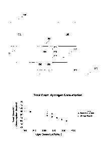
[0085] FIG. 6 shows the total hydrogen consumption during dewaxing for
production
of the summer grade and winter grade diesels described above. As shown in FIG.
6,
increasing the upper cut point for the light diesel fraction results in a
lower hydrogen
consumption during dewaxing. This is due in part to the reduced volume of the
heavy
CA 02854869 2014-05-07
WO 2013/070566 PCT/US2012/063641
- 29 -
diesel being dewaxed as the upper cut point for the light diesel is increased.
FIG. 6 also
demonstrates that it is desirable to cut a light diesel fraction so that the
light diesel has a
desired cloud point prior to blending with the dewaxed heavy diesel fraction.
Additional Embodiments
10086] Embodiment I. A method for producing distillate products is
provided,
comprising: hydrotreating a feedstock under effective hydrotreating
conditions;
fractionating at least a portion of the hydrotreated feedstock to form, a
heavy diesel
fraction and a light diesel fraction; dewaxing the heavy diesel fraction under
effective
dewaxing conditions to produce a dewaxed heavy diesel fraction having a cloud
point of
about -10 C or less; and fractionating the dewaxed heavy diesel fraction to
form at least
a heavy diesel product, the fractionation further producing an additional
fraction.
[0087] Embodiment 2. A method according to embodiment I, wherein the at
least a
portion of hydrotreated feedstock is passed into a first separate volume of a
divided wall
separator for fractionation, the heavy diesel fraction being withdrawn from
the first
separate vol um.e of the divided wall fractionator; wherein the dewaxed heavy
diesel
fraction is passed into a second separate volume of the divided wall
fractionator, the
heavy diesel product being withdrawn from the second separate volume; and
wherein the
light diesel fraction and the additional fraction are withdrawn from a common
volume of
the divided wall fractionator as a combined light diesel fraction.
[0088] Embodiment 3. A method according embodiment 2, wherein the cloud
point
of the heavy diesel product is +/- 1 C of the cloud point of the combined
light diesel
fraction.
10089] Embodiment 4. A method according to embodiments 2 or 3, further
comprising combining at least a portion of the combined light diesel fraction
with the
heavy diesel product to form a combined diesel product, the combined diesel
product
having a cloud point that is +1- 1 C of the cloud point of the combined light
diesel
fraction and the heavy diesel product.
CA 02854869 2014-05-07
WO 2013/070566 PCT/US2012/063641
30 -
[0090] Embodiment 5. A method according to any of embodiments 2 to 4,
further
comprising withdrawing a naphtha fraction from the common volume of the
fractionator.
[0091] Embodiment 6. A method according to any of the above embodiments,
wherein the effective hydrotreating conditions comprise a pressure of from
about 300
psig (2.1 MPa) to about 3000 psig (20.7 MPa), a temperature of from about 500
F
(260 C) to about 800 F (427 C), and a space velocity of from about 0.3 hr-1 to
about 5.0
hr, and wherein the effective dewaxing conditions include temperatures of
about 500 F
(260 C) to about 750 F (399 C), pressures of about 400 psig (2.8 MPa) to about
800
psig (5.5 MPa), an LHSV of about 0.5 hr-1 to about 5.0 hr--1, and a space
velocity of from
about 0.3 hr-' to about 5.0 hr-]
[0092] Embodiment 7. A method according to any of the above embodiments,
wherein the dewaxed heavy diesel fraction has a cloud point of about -30 C or
less.
[0093] Embodiment 8. A method according to any of the above embodiments,
wherein at least one of the heavy diesel fraction corresponds to a bottoms
fraction.
[0094] Embodiment 9. A method according to any of the above embodiments,
wherein the light diesel fraction or the combined light diesel fraction
corresponds to a jet
fuel fraction.
[0095] Embodiment 10. A method according to any of the above embodiments,
N;vherein the nitrogen content of the feedstock is at least about 500 wppm.
[0096] Embodiment 11. A method according to any of the above embodiments,
wherein the sulfur content of the feedstock is at least about 100 wppm, the
effective
hydrotreating conditions being effective to reduce the sulfur content to about
15 wppm or
less.
[0097] Embodiment 12. A method according to any of the above embodiments,
wherein the at least a portion of hydrotreated feedstock is fractionated at a
cut point of
CA 02854869 2014-05-07
WO 2013/070566
PCT/US2012/063641
31 --
about 575 F (302 C) or less to form -the heavy diesel. fraction and the first
light diesel
fraction.
[0098]
Embodiment 13. A method according to embodiment 1, further comprising
combining at least a portion of the heavy diesel product and the light diesel
fraction to
form a combined diesel product, the combined diesel product having
substantially the
same cloud point as the heavy diesel product and the light diesel fraction.