Note: Descriptions are shown in the official language in which they were submitted.
CA 02855294 2014-06-25
. .
A WORK PIECE CHUCK OF A MANIPULATOR
BACKGROUND OF THE INVENTION
Field of Invention
The present invention pertains to the field of mechanical technology. The
invention
relates to a work piece chuck of a manipulator, and particularly, to a chuck
of a manipulator
for a water faucet.
Related Art
In the manufacturing industry, in order to guarantee the quality and aesthetic
appearance of the products, sanding for components to be cast and finishing
for components
to be processed are important processes for molding of components. Some
problems may
exist in the casting shape and machining size for components of complex
appearance,
particularly water faucets for bathroom, including deviation, variation on
wall thickness and
inconsistency in shapes and positions, for which the components could not be
processed by
special machine tools. Therefore, ordinary finishing is done by using man
power on
abrasive belt machine and cloth wheel machine. As heat will be generated by
finishing
and friction and a large amount of metallic dust will be produced in the
process of finishing,
such working conditions are harmful to humans. Moreover, thanks to
unreliability of
manual operation, the finishing depth can not be easily and precisely
determined.
Consequently, low operation efficiency is resulted and the uniformity and
reliability of
finishing products could not be sufficiently guaranteed.
As a result of the unreliability in manual polishing and hazards to human
health,
automatic polishing is generally employed at present. That is to say, after
the work piece
is caught by the manipulator arm, the work piece can be polished and finished
on the
polisher according to a preset path, which provides a high polishing
efficiency and reduces
1
CA 02855294 2014-06-25
the labor intensity of the workers. When an ordinary manipulator arm is used
to clamp the
work piece, the chuck at the front end of the manipulator arm will extend into
the work
piece, and several claws at the front end of the chuck are pressed
circumferentially against
the inner side wall of the work piece. The work piece is caught by using the
force exerted
by the claws against the inner side wall of the work piece. As the chuck
exerts a force
against the inner side wall of the work piece through the claws and no
specific positioning
mechanism is used, each of the claws at the front end of the chuck cannot be
guaranteed to
be on the same plane, which tends to influence the uniformity of finishing of
the work piece
surface and impair the reliability of connection of the chuck with the work
piece.
SUMMARY OF THE INVENTION
In order to address the aforesaid problems existing in the prior art, the
present invention
provides a work piece chuck of a manipulator which could be used to more
conveniently
hold the work piece and connected with the work piece in a firmer manner.
It is one object of the present invention to provide a work piece chuck of a
manipulator.
The chuck comprises a chuck sleeve and an ejector pin set within the chuck
sleeve. An
elastic clamping element is provided at the front end of the chuck sleeve. The
ejector pin
could move between a first position and a second position along the axial
direction of the
chuck sleeve. When the ejector pin is in the first position, the outer
circumference of the
ejector pin extrudes the clamping element to distort and expand outward to
form an
expansion state. When the ejector pin is in the second position, the outer
circumference
of the ejector pin is out of contact with the clamping element to restore the
clamping
element.
In the work piece chuck of a manipulator of the invention, there are several
clamping
elements arranged into an annular port which is formed by several indentations
opened at
the front end of the chuck sleeve along the axial direction of the chuck
sleeve. Such a
configuration easily forms the expansion structure.
2
CA 02855294 2014-06-25
In the work piece chuck of a manipulator of the invention, an engagement part
is
provided at the end of the outer circumference of the clamping element and
projects from
the outer circumference of the clamping element. The engagement part could
reduce the
moving distance of the elastic piece.
In the work piece chuck of a manipulator of the invention, the ejector pin and
the chuck
sleeve are circumferentially fixed, the inner end of the ejector pin is
connected with a
power element, and the outer end of the ejector pin extends out of or retracts
into the front
end of the chuck sleeve under the action of the power element.
When the work piece chuck of a manipulator of the invention is used to hold
the work
piece, the chuck extends into the work piece and the outer end of the ejector
pin extends
out of the front end of the chuck sleeve under the action of the power
element. As
several indentations are opened at the front ends of the chuck sleeve along
the axial
direction, the front tend of the chuck sleeve is elastic. When the front end
of the ejector
pin extends out, it extrudes the front end of the chuck sleeve outward, and
front end of the
chuck sleeve expands outward. The front end of the chuck sleeve gradually
expands to
attach to the inner side wall of the work piece as the ejector pin
continuously extends out.
In the meantime, the engagement part at the outer side of the front end of the
chuck sleeve
will be engaged with the inner side wall of the work piece. As a result, the
chuck is
firmly held by the chuck.
In the work piece chuck of a manipulator of the invention, the front end of
the chuck
sleeve is conical. The conical shape of the front end of the chuck sleeve
adapts the chuck
sleeve to work pieces of different diameters including pipes, water faucets
and valves.
When the ejector pin is driven by the power element to move forward, the front
end of the
ejector pin will extrude the front end of the chuck sleeve outward, for which
the front end
of the chuck sleeve will expand outward.
In the work piece chuck of a manipulator of the invention, the front end of
the ejector
pin is also conical, and the taper angle of the front end of the ejector pin
is larger than that
3
CA 02855294 2014-06-25
of the front end of the chuck sleeve. The outer end of the ejector pin is
driven by the
power element to move outward relative to the front end of the chuck sleeve.
As the
taper angle of the outer end of the ejector pin is larger than that of the
front end of the
chuck sleeve, the front end of the chuck sleeve will be extruded outward to
expand when
the outer end of the ejector pin extends outwards. In the work piece chuck of
a
manipulator of the invention, the engagement part forms an annular shoulder on
the outer
circumference of the front end of the chuck sleeve.
When the front end of the chuck sleeve is extruded by the outer end of the
ejector pin
to expand outward, the annular shoulder on the outer side of the front end of
the chuck
sleeve will expand outward as well and be finally engaged with the inner side
wall of the
work piece. Particularly, when the work piece is a water faucet, the annular
shoulder at
the front end of the chuck sleeve will be pressed against the bottom of the
threaded part on
the inner side wall of the water faucet.
In the work piece chuck of a manipulator of the invention, positioning
protrusions are
provided at the front end of the ejector pin. When the ejector pin extends
into the work
piece, the positioning protrusions will cooperate with the inner bores of the
work piece to
ensure that the work piece will not rotate relative to the chuck.
In the work piece chuck of a manipulator of the invention, three positioning
protrusions
are provided. When the work piece is a water faucet, the said three
positioning
protrusions at the outer end of the ejector pin are exactly in cooperation
with three water
passage holes on the valve core of the water faucet.
In the work piece chuck of a manipulator of the invention, a position limiter
is disposed
on the central side of the ejector pin and a position limiting groove is
correspondingly
disposed on the central side of the chuck sleeve. The position limiter is
located within
the position limiting groove. The width of the position limiter is identical
to the width of
the position limiting groove and the length of the position limiting groove is
larger than
that of the position limiter.
4
CA 02855294 2014-06-25
As the width of the position limiter is identical to that of the position
limiting groove,
the ejector pin cannot rotate relative to the chuck sleeve in the
circumferential direction.
Moreover, the length of the position limiting groove is larger than that of
the position
limiter, so that the axial movement of the ejector pin in the axial direction
will not be
restricted.
In the work piece chuck of a manipulator of the invention, the positioning
protrusion (5)
is provided with a perforative air outlet. The inner cavity of the ejector pin
is hollow and
in communication with the air outlet. An air exiting means is provided on the
ejector pin
for blowing air into the work piece through the air outlet.
A large amount of residuals are left within the work piece when the work piece
is
processed at the processing center. When the work piece is to be held by the
manipulator
for polishing and finishing, air is provided into the work piece via the air
outlet on the
ejector pin in communication with the inner cavity, and the residuals within
the work
piece could be blown away. That is to say, the work piece can be polished and
finished
while the residuals can be cleared in the meantime
In the work piece chuck of a manipulator of the invention, the air exiting
means
includes an air inlet opened on the position limiter and an air hole opened on
the inner side
wall of the ejector pin corresponding to the air inlet on the position limiter
The air inlet on the position limiter is in communication with one air supply
in such a
manner that the air supply provides air to the inner cavity of the ejector pin
via the air hole
and finally blows air into the work piece via the air outlet on the
positioning protrusion.
Consequently, the air exiting from the air outlet on the positioning
protrusion can blow the
iron residuals within the work piece away.
In the work piece chuck of a manipulator of the invention, two annular seal
grooves are
opened on the side of the ejector pin and an annular seal ring is provided
between the
annular seal groove and the inner side wall of the chuck sleeve. An annular
groove is
5
CA 02855294 2014-06-25
further formed between two annular seal grooves on the side of the ejector
pin. The air
exiting means includes an air hole which is provided at the annular groove and
in
communication with the inner cavity of the ejector pin and an air inlet which
is disposed
on the side of the chuck sleeve and in communication with the air hole. The
air inlet is
always located between two annular seal grooves when the ejector pin moves
relative to
the chuck sleeve in the axial direction.
An air supply is connected with the air inlet on the side of the chuck sleeve.
While
the ejector pin is moved, the air enters into the inner cavity of the ejector
pin from the air
supply through the air inlet and the air hole, and eventually enters into the
work piece via
the air outlets of the positioning protrusions for cleaning. As the air inlet
is always
located between two annular seal grooves on the side of the ejector pin when
the ejector
pin moves, the air will not leak from the spacing between the ejector pin and
the chuck
sleeve.
In the work piece chuck of a manipulator of the invention, a stop edge is
formed on the
inner side wall at the inner end of the chuck sleeve and a stop shoulder is
formed on the
outer side at the inner end of the ejector pin to be pressed against the stop
edge. When
the stop shoulder at the inner end of the ejector pin is pressed against the
stop edge on the
inner side wall at the inner side of the chuck sleeve, the front end of the
ejector pin
extends by the longest distance relative to the front end of the chuck sleeve.
In the work piece chuck of a manipulator of the invention, the inner end of
the ejector
pin is threaded with a transition sleeve and a connection hole is formed on
the transition
sleeve to be connected with the power element mounted in the manipulator. The
ejector
pin is connected with the power element through the connection hole on the
transition
sleeve, and the power element could the block the inner cavity of the ejector
pin at the
inner end of the ejector pin in the meantime.
In the work piece chuck of a manipulator of the invention, the inner end of
the chuck
sleeve is threaded with a positioning cylinder, and the end of the positioning
cylinder is
6
CA 02855294 2015-12-17
provided with a flange to be connected with the manipulator. When the work
piece chuck
of a manipulator of the invention is in operation, the chuck sleeve could be
fixedly
connected with the front end of the manipulator by using the flange at the end
of the
positioning cylinder.
The work piece chuck of a manipulator of the invention has the following
advantages over the prior art.
First, by using the work piece chuck of a manipulator of the invention, the
front
end of the chuck sleeve expands outward to engage the engagement part with the
work
piece when the ejector pin is pushed out of the chuck sleeve. The work piece
chuck not
only has a simple structure, but also is firmly connected with the work piece
for which
the work piece does not tend to fall off or translocate.
Second, by using the work piece chuck of a manipulator of the invention, three
positioning protrusions at the front end of the ejector pin could be in
cooperation with the
inner bores of the work piece, and the chuck will not rotate relative to the
work piece.
Meanwhile, the ejector pin and the chuck sleeve are circumferentially fixed
through the
position limiter and position limiting groove, for which higher reliability is
provided in
operation.
Third, by using the work piece chuck of a manipulator of the invention, air
could
be provided into the work piece via the air outlets through the air exiting
means on the
ejector pin. As a result, the residuals within the work piece could be
cleared, which
provides higher use value.
Accordingly, in one aspect the present invention resides in a work piece chuck
of a
manipulator, wherein, the chuck comprises a chuck sleeve and an ejector pin
set within the
chuck sleeve, an elastic clamping element is provided at the front end of the
chuck sleeve,
the ejector pin could move between a first position and a second position
along the axial
direction of the chuck sleeve, when the ejector pin is in the first position,
the outer
circumference of the ejector pin extrudes the clamping element to distort and
expand
outward to form an expansion state, and when the ejector pin is in the second
position, the
outer circumference of the ejector pin is out of contact with the
7
CA 02855294 2015-12-17
clamping element to restore the clamping element; the ejector pin and the
chuck sleeve are
circumferentially fixed, the inner end of the ejector pin is connected with a
power element,
and the outer end of the ejector pin extends out of or retracts into the front
end of the chuck
sleeve under the action of the power element; an engagement part is provided
at the end of
the outer circumference of the clamping element and projects from the outer
circumference of
the clamping element; the engagement part forms an annular shoulder on the
outer
circumference of the front end of the chuck sleeve; several positioning
protrusions are
provided at the front end of the ejector pin.
Further scope of applicability of the present invention will become apparent
from
the detailed description given hereinafter. However, it should be understood
that the
detailed description and specific examples, while indicating preferred
embodiments of the
invention, are given by way of illustration only, since various changes and
modifications
within the scope of the invention will become apparent to those skilled in the
art from this
7a
CA 02855294 2014-06-25
detailed description.
BRIEF DESCRIPTION OF THE DRAWINGS
The present invention will become more fully understood from the detailed
description
given herein below for illustration only, and thus are not limitative of the
present invention,
and wherein:
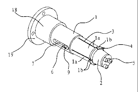
FIG. 1 is a stereogram of the work piece chuck of a manipulator according to
the first
embodiment;
FIG. 2 is a section view of the work piece chuck of the manipulator according
to the
first embodiment; and
FIG. 3 is a partial section view of the air exiting means of the work piece
chuck of the
manipulator according to the second embodiment.
DETAILED DESCRIPTION OF THE INVENTION
The embodiments of the invention will be described below and the technical
solutions
of the invention will be further illustrated in connection with the
accompanying figures.
However, the present invention shall not be limited to these embodiments.
First Embodiment
As shown in fig. 1, the chuck is provided at the front end of the manipulator,
comprising a chuck sleeve and an ejector pin 2 set within the chuck sleeve 1.
An elastic
8
CA 02855294 2014-06-25
clamping element la is provided at the front end of the chuck sleeve 1. The
ejector pin 2
could move between a first position and a second position along the axial
direction of the
chuck sleeve 1. When the ejector pin 2 is in the first position, the outer
circumference of
the ejector pin 2 extrudes the clamping element la to distort and expand
outward to form an
expansion state. When the ejector pin 2 is in the second position, the outer
circumference
of the ejector pin 2 is out of contact with the clamping element 1 a to
restore the clamping
element la. The ejector pin 2 is in the second position in use and the chuck
sleeve 1 is in
a normal status and inserted into the inner bore of the work piece such as a
water faucet.
When the ejector pin 2 is moved into the first position, the clamping element
la is in the
expansion state to hold the work piece. When the ejector pin 2 is moved into
the second
position, the work piece is no longer held by the clamping element.
Specifically, referring to figs. 1 and 2, the chuck sleeve 1 is cylindrical
and the ejector
pin 2 is columnar. A stop edge 14 is formed on the inner side wall at the
inner end of the
chuck sleeve 1. A stop shoulder 15 is formed on the outer circumference at the
inner end
of the ejector pin 2 to be pressed against the stop edge 14. The inner end of
the chuck
sleeve 1 is threaded with a positioning cylinder 18. The end of the
positioning cylinder 18
is provided with a flange 19 to be connected with the manipulator. The inner
end of the
ejector pin 2 is threaded with a transition sleeve 16 on which a connection
hole 17 is
formed to be connected with the power element mounted in the manipulator. The
front
end of the ejector pin 2 could retract relative to the front end of the chuck
sleeve 1 under the
action of the power element.
Four clamping elements la are provided and arranged into an annular port which
is
formed by four indentations 3 at the front end of the chuck sleeve 1 evenly
distributed along
the axial direction of the chuck sleeve 1. An arc structure having an inner
diameter larger
than the width of the indentation 3 is provided at the bottom of the
indentation 3 for
increasing the elasticity of the clamping elements la. With reference to figs.
1 and 2, the
clamping elements la are configured to be an arc plate-like structure and
elastic. Such a
structure easily forms an expansion structure and engagement parts lb are
formed on the
9
CA 02855294 2014-06-25
outer circumference of the front end of the chuck sleeve 1 which can be
engaged with the
work piece. The engagement parts lb project from the outer circumference of
the
clamping elements la. As such, the engagement parts lb form an annular
shoulder 4 on
the outer circumference at the front end of the chuck sleeve 1. The front end
of the chuck
sleeve 1 and the front end of the ejector pin 2 are both conical. The taper
angle of the
front end of the ejector pin 2 is larger than that of the front end of the
chuck sleeve 1 and
the front end of the ejector pin 2 partly extends out of the front end of the
chuck sleeve 1.
By using the said configuration, the expansion displacement of the clamping
element la
could be controlled by the extension distance of the ejector pin 2. Not only
can different
clamping forces be selected as desired, but also the error and wear rate could
be adjusted by
the moving distance of the ejector pin when the ejector pin and the chuck
sleeve wear.
The ejector pin 2 and the chuck sleeve 1 are circumferentially fixed. A
position
limiter 6 is disposed on the central side of the ejector pin 2 and a position
limiting groove 7
is correspondingly disposed on the central side of the chuck sleeve 1. The
position limiter
6 is located within the position limiting groove 7. The width of the position
limiter 6 is
identical to the width of the position limiting groove 7 and the length of the
position
limiting groove 7 is larger than that of the position limiter 6.
As shown in fig. 2, three positioning protrusions 5 are formed on the front
end of the
ejector pin 2. The positioning protrusion 5 is provided with a perforative air
outlet 8.
The inner cavity of the ejector pin 2 is hollow and in communication with the
air outlet 8.
An air exiting means is provided on the ejector pin 2 for blowing air into the
work piece
through the air outlet 8. The air exiting means includes an air inlet 9 opened
on the
position limiter 6 and an air hole 10 opened on the inner side wall of the
ejector pin 2
corresponding to the air inlet 9 on the position limiter 6.
The work piece chuck of the manipulator is fixed on the front end of the
manipulator
through the flange 19 on the positioning cylinder 18 threaded with the inner
end of the
chuck sleeve 1. The power element generally includes an air cylinder within
the
CA 02855294 2014-06-25
manipulator. The piston rod of the air cylinder extents from the positioning
cylinder 18
into the inner end of the chuck sleeve 1 and is connected with the connection
hole 17 on the
transition sleeve 16 threaded with the inner end of the ejector pin 2. As
such, the ejector
pin 2 is driven by the piston rod of the air cylinder to move relative to the
chuck sleeve 1.
The work piece is held by the work piece chuck of the manipulator in the
following
process. The chuck is brought by the manipulator to move onto the work piece.
The air
cylinder within the manipulator is driven into operation. The ejector pin 2 is
brought by
the piston rod of the air cylinder to move downward therewith and extend into
the work
piece. As both the front end of the ejector pin 2 and that of the chuck sleeve
1 are conical,
and the taper angle of the front end of the ejector pin 2 is larger than that
of the front end of
the chuck sleeve 1, the front end of the ejector pin 2 extrudes the front end
of the chuck
sleeve 1 outward when the ejector pin 2 moves downward. As several indentions
3 are
opened in the axial direction on the front end of the chuck sleeve 1, the
front end of the
chuck sleeve 1 will expand outward when it is extruded outwards. The front end
of the
chuck sleeve 1 continuously expands outward and is finally pressed against the
inner side
wall of the work piece as the ejector pin gradually moves downward. Meanwhile,
the
annular shoulder 4 disposed outside of the edge of the front end of the chuck
sleeve 1 is
engaged with the inner side wall of the work piece. When the work piece is a
water facet
and the ejector pin 2 is pressed against the valve core of the water faucet,
the annular
shoulder 4 disposed outside of the edge of the front end of the chuck sleeve I
will be firmly
engaged with the lowest end of the thread connection part on the inner side
wall of the
water faucet, which guarantees the firm connection of the chuck with the work
piece.
Moreover, when the front end of the ejector pin 2 moves downward by the
largest
distance, three positioning protrusions 5 at the front end of the ejector pin
2 are inserted into
the inner bores of the work piece. When the work piece is a water faucet, the
positioning
protrusions 5 are inserted into the water passage hole of the valve core of
the water faucet.
It is ensured that the chuck will not rotate relative to the work piece by the
cooperation
between the positioning protrusions 5 and the inner bores of the work piece,
for which the
11
CA 02855294 2014-06-25
work could be reliably held. Furthermore, as the ejector pin 2 and the chuck
sleeve 1 are
fixed in the circumferential direction, the ejector pin 2 and chuck sleeve 1
will not rotate
relative to each other.
As a large amount of minute residuals are left within the work piece when the
work
piece is processed at the processing center, the air inlet 9 on the position
limiter 6 on the
side of the ejector pin 2 is communicated with an air supply before the work
piece is held
by the manipulator for polishing and finishing, and the inner cavity of the
ejector pin 2 is
supplied with air by the air supply. The positioning protrusion 5 has a
perforative air
outlet 8 in communication with the inner cavity of the ejector pin 2. As such,
the air thus
supplied could enter into the work piece through the air outlet 8. As a
result, the work
piece can be polished and finished while the residuals within the work piece
can be cleared
in the meantime. After the work piece is polished and finished, the air supply
is separate
from the air inlet 9, and then the air cylinder is controlled to restore the
piston rod of the air
cylinder to the initial state. The ejector pin 2 is driven by the piston rod 2
to retract into
the chuck sleeve 1. The front end of the chuck sleeve 1 retracts and is
separate from the
work piece. The chuck eventually exits the work piece.
Second Embodiment
The structure and principle of this embodiment are substantially the same as
those of
the second embodiment except that, as shown in fig. 3, two annular seal
grooves 11 are
opened on the side of the ejector pin 2 and an annular seal ring 12 is
provided between the
annular seal groove 11 and the inner side wall of the chuck sleeve 1. An
annular groove
13 is further formed between two annular seal grooves 11 on the side of the
ejector pin 2.
The air exiting means includes an air hole 10 which is provided at the annular
groove 13
and in communication with the inner cavity of the ejector pin 2 and an air
inlet 9 which is
disposed on the side of the chuck sleeve 1 and in communication with the air
hole 10. The
air inlet 9 is always located between two annular seal grooves 11 when the
ejector pin 2
moves relative to the chuck sleeve 1 in the axial direction.
12
CA 02855294 2015-12-17
An air supply is connected with the air inlet 9 on the side of the chuck
sleeve
1. While the ejector pin 2 is moved, the air enters into the inner cavity of
the ejector
pin 2 from the air supply through the air inlet 9 and the air hole 10, and
eventually
enters into the work piece via the air outlets 8 of the positioning
protrusions 5 for
cleaning. As the air inlet 9 is always located between two annular seal
grooves 11 on the
side of the ejector pin 2 when the ejector pin 2 moves, the air will not leak
from the
spacing between the ejector pin 2 and the chuck sleeve 1.
The embodiments described herein are merely illustrative of preferred aspects
of
the invention. It is obvious for those skilled in the art to make various
modifications,
supplements or alternatives to these embodiments without departing from the
scope of the
invention as defined by the appended claims.
13
CA 02855294 2014-06-25
List of Reference Numerals
1 Chuck Sleeve
la Clamping Element
lb Engagement Part
2 Ejector Pin
3 Indentation
4 Annular Shoulder
5 Positioning Protrusion
6 Position Limiter
7 Position Limiting Groove
8 Air Outlet
9 Air Inlet
10 Air Hole
11 Annular Seal Groove
12 Annular Seal Ring
13 Annular Groove
14 Stop Edge
15 Stop Shoulder
16 Transition Sleeve
14
CA 02855294 2014-06-25
17 Connection Hole
18 Positioning Cylinder
19 Flange