Note: Descriptions are shown in the official language in which they were submitted.
CA 02855878 2014-07-03
SELF REGULATING FLUID BEARING HIGH PRESSURE
ROTARY NOZZLE WITH BALANCED THRUST FORCE
BACKGROUND OF THE INVENTION
[0001] The present invention provides a simplified and reliable construction
for a
high-pressure rotating water jet nozzle which is particularly well suited to
industrial
uses where the operating parameters can be in the range of 1,000 to 40,000
psi,
rotating speeds of 1000 rpm or more and flow rates of 2 to 50 gpm. Under such
use
the size, construction, cost, durability and ease of maintenance for such
devices
present many problems. Combined length and diameter of such devices may not
exceed a few inches. The more extreme operating parameters and great reduction
in
size compound the problems. Pressure, temperature and wear factors affect
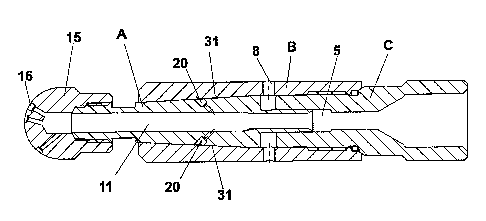
durability
and ease of maintenance and attendant cost, inconvenience and safety in use of
such
devices. Use of small metal parts and poor quality of materials in such
devices may
result in their deterioration or breakage and related malfunctioning and
jamming of
small spray discharge orifices or the like. The present invention addresses
these
issues by providing a simplified construction with a greatly reduced number of
parts
and a design in which net operating forces on nozzle components are minimized.
SUMMARY OF THE INVENTION
[0002] This invention provides a nozzle for use in a high pressure (HP) range
of
approximately 1,000 to 40,000 psi having a "straight through" fluid path to a
jet head
at an end of the device where the head is preferably capable of providing
rotating
coverage of greater than hemispherical extent, including the area directly
along the
axis of rotation of the device. In a typical nozzle assembly the internal
forces resulting
from such operating pressures tend to create an axial thrust force acting
against the
nozzle shaft with the force corresponding to the operating pressure and cross
sectional
area of the shaft. An example of a prior art device using mechanical bearings
is shown
in Applicants' prior U.S. Pat. No. 6,059,202. This prior art device provides
the benefit
that pressurized operating fluid can take a "straight through" from the inlet
for the fluid
source to the nozzle head. However, in this device the rotating nozzle shaft
is
supported against the internal axial thrust forces by a series of stacked
bearings, with
plural bearings being used to bear the relatively high thrust load without
increasing the
1
CA 02855878 2014-07-03
diameter of the device. In such devices the mechanical bearings have been used
to
serve as both radial and thrust bearings, however the size and/or quantity of
such
bearings has been dictated primarily by the need to resist thrust forces.
[0003] It has generally been considered desirable to keep the diameter of any
rotating portions of a nozzle smaller than the largest diameter of such a
nozzle so that
contact between the rotating portions and any surface being cleaned is
minimized or
eliminated thereby minimizing abrasive wear to the nozzle and interference
with the
rotational movement of the nozzle jets. Other prior art devices have used
nozzles
which rotate around a central tube which provides the fluid source. However
for the
aforementioned reason, such devices, while being able to provide a cylindrical
path of
coverage with their rotating bodies, have not been well adapted to both
providing a
rotating coverage which can include a path very close to the rotational axis
of the
device and an "straight-through" fluid path.
[0004] In contrast to such prior art devices, the device of the present
invention
provides a much simplified structure which also provides a straight-through
fluid path
in which the pressure of the operating fluid is also allowed to reach and act
upon
opposing surfaces of the rotating nozzle shaft so as to effectively balance
any axial
thrust force. Further a small detachable jet head having a diameter smaller
than the
body of the nozzle can be attached at the leading end of the nozzle to provide
an
improved coverage pattern for the high-pressure fluid. This is accomplished by
providing a "bleed hole" to allow a small portion of pressurized fluid to
reach a chamber
or channel within the housing but outside the exterior of the forward portion
of the
nozzle shaft where the fluid pressure can act upon the nozzle shaft with a
sufficient
axial component so as to balance the corresponding axial component against the
nozzle shaft created by the internal fluid pressure. This chamber or channel
communicates with the exterior of the device by means of a slightly tapered
frusto-
conical bore surrounding a corresponding tapered portion of the shaft which
further
allows the fluid to flow between the body and the shaft to facilitate or
lubricate the shaft
rotation.
[0005] Because of the tapered shape, the spacing between the housing and the
shaft
varies slightly with axial movement of the shaft and creates a "self
balancing" effect in
which the axial forces upon the shaft remain balanced and there is always some
fluid
2
CA 02855878 2014-07-03
flowing between the shaft and housing which helps decrease contact and
resulting
wear between these two components. Due to the lack of any significant
imbalanced
radial forces and the fluid flowing between the surfaces of the shaft and
housing, a
device of the present invention can be constructed without need for mechanical
bearings.
[0006] In addition, around the inlet end of the shaft an annular groove or
channel is
provided in the inside surface of the housing body abutting the inlet end
portion of the
shaft. Surprisingly, this annular channel enhances bleed flow of fluid around
the inlet
end of the shaft to substantially reduce the effects of rotationally induced
precession
on the shaft, thus improving the operability of the nozzle.
[0007] In one aspect, the present invention provides a nozzle assembly for
spraying
high pressure fluid against an object, the assembly including: a hollow
housing body;
a hollow tubular shaft member coaxially rotatable within the housing body and
having
a fluid inlet end within and near one end of said housing body, said shaft
member
having an outlet end near a second end of the housing body for securing a
spray head
thereto for rotation with the shaft, said shaft member having a central axial
passage to
conduct fluid axially from said inlet end through the passage to said outlet
end, said
body having a high pressure fluid inlet passage communicating with said
central
passage of said shaft; a regulating passage formed between said housing body
and
said shaft near said outlet end of said shaft; and a passage communicating
between
the central passage of the shaft and a portion of the outer surface of the
shaft member,
wherein pressure of said fluid within said regulating passage acts axially
upon said
shaft to counterbalance axial force on said shaft exerted by fluid pressure
acting upon
said inlet end of said shaft, wherein the housing body has an inlet bearing
area
supporting the inlet end of the tubular shaft member and has a single annular
channel
formed in the housing body around the inlet bearing area.
[0008] The regulating passage may be a tapered frusto-conical gap defined
between
said tubular shaft and said housing body. The volume of the regulating passage
may
be variable as said tubular shaft moves axially within said housing body.
[0009] During pressurized operation of the nozzle, axial forces on said
tubular shaft
may reach equilibrium, so that there is no axial contact between said tubular
shaft and
said housing body. During pressurized operation of the nozzle, said tubular
shaft may
3
CA 02855878 2014-07-03
be supported within said housing entirely by a flow of operating fluid between
said
shaft and said housing.
[0010] In another aspect, the present invention provides a nozzle assembly for
rotatably spraying high pressure cleaning fluid against an object to be
cleaned, the
assembly including: a hollow cylindrical housing body; a hollow tubular shaft
member
coaxially carried within the housing body, the shaft member having a fluid
inlet end
within and near one end of said housing body, said shaft member having an
outlet end
projecting from a second end of the housing body, the outlet end configured to
receive
a spray head fastened thereto for rotation of the head with the shaft, said
shaft member
having a central passage to conduct fluid axially from said inlet end axially
through the
inlet end to said outlet end, said housing body having a high pressure fluid
inlet
passage axially communicating with said central passage of said shaft; an
inner wall
of said housing body and a portion of said shaft near said outlet end of said
shaft
having complementary tapered surface shapes, together forming a regulating
passage
therebetween; said shaft member having one or more bores communicating between
the central passage of the shaft member and the regulating passage, wherein
pressure of cleaning fluid within said regulating passage acts axially upon
said shaft
to counter axial force on said shaft resulting from fluid pressure acting upon
said inlet
end of said shaft; and wherein the housing body has an inlet bearing area
supporting
the inlet end of the tubular shaft member and the housing body has a single
annular
channel formed around the inlet bearing area abutting the inlet end portion of
the shaft
member.
[0011] The regulating passage may be a frusto-conical gap defined between said
tubular shaft and said housing body. The volume of said regulating passage may
vary
as said tubular shaft moves axially within said housing body.
[0012] During pressurized operation of the nozzle, axial forces on said
tubular shaft
may reach equilibrium minimizing axial contact between said tubular shaft and
said
housing body. During pressurized operation of the nozzle, said tubular shaft
may be
supported within said housing entirely by fluid between said shaft and said
housing
body.
4
CA 02855878 2014-07-03
DESCRIPTION OF THE DRAWINGS
[0013] FIG. 1 is a cross-section of the nozzle of the preferred embodiment in
which
a tapered regulator passage also serves as a balancing chamber.
[0014] FIG. 2 is a cross-section of the nozzle of an alternative embodiment in
which
the balancing chamber is separate from the tapered regulator passage.
[0015] FIG. 3 is a cross-section corresponding to FIG. 2 showing the shaft in
a
slightly different axial position.
[0016] FIG. 4 is a cross-section of a structural variation of the nozzle shown
in FIG.
1 in which an annular groove is provided in each of the bearing areas of the
nozzle
body.
[0017] FIG. 5 is a cross-sectional view of another embodiment of a nozzle in
accordance with the present invention.
[0018] FIG. 6 is a cross-sectional view of another embodiment of a nozzle in
accordance with the present invention.
DETAILED DESCRIPTION OF THE INVENTION
[0019] As can be seen most clearly in FIG. 2, one embodiment of the present
invention includes a simple three-piece rotary nozzle structure. A hollow
cylindrical
rotary shaft A is contained in a two part housing or body comprised of an
inlet portion
C and an outlet portion B. The housing portions are secured together and
sealed using
threading or other similar fastening means 2 which allows assembly and
disassembly
of the device including allowing shaft A to be readily inserted or removed.
The inlet
portion C provides an inlet 3 for high-pressure fluid fed to the device by
hose or other
similar means attached to the inlet by any suitable means, most commonly a
mated
threaded fitting. A suitable material for each of the nozzle portions will
have fairly high
strength and resistance to galling, for example, any of various high nickel
stainless
steels. A bronze tubular shaft or bronze body may alternatively be used for
enhanced
galling resistance. A surface treatment or plating may be used for any known
benefits
such as lubricity or abrasion resistance.
[0020] At the opposite end of the housing inlet portion is a cylindrical
cavity 5 which
receives the inlet end 6 of the rotating shaft A. The annular interface 7
between the
housing and shaft is sized so as to minimize leakage while still allowing
rotation of the
CA 02855878 2014-07-03
shaft A with a slight cushion of fluid. Typically the gap of the interface 7
will be
approximately 0.0025" to 0.0005". Some passage of fluid at the interface 7 is
desirable
in order to allow a fluid layer to facilitate the rotating movement between
the shaft A
and outlet portion B. Elimination of the need of a seal at interface 7 reduces
manufacturing expense and complexity in providing such a seal. Outlet portion
B is
provided with radial "weep" holes 8 to the exterior for escape of fluid
passing the
interface 7 or other paths along the exterior of shaft A.
[0021] The shaft inlet 10 is open to the cavity 5 to of provide direct flow of
fluid into
the central of bore 11 of the shaft A. Under normal operation the pressurized
fluid
exerts an axial force on the inlet end 6 of shaft A which will be referred to
herein as
the "input force." This force is directly proportional to (1) the area of the
inlet end 6
perpendicular to the direction of fluid flow and (2) the pressure of the
fluid. It is this
axial force which the present invention is intended to counteract with an
equal
opposing force.
[0022] As the fluid enters the shaft most of the fluid will pass through the
central bore
of the shaft to exit through the nozzle head 15 attached to the outlet end 12
of the
shaft. Head 15 will typically be provided with exit holes or orifices 16
positioned to
direct high pressure fluid toward a surface to be cleaned and oriented to
impart a
reactive force to rotate the head and shaft.
[0023] A significant feature which eliminates the need for dedicated thrust
bearings
is the provision of one or more passages or bores 20 which communicate between
the
central bore 11 of the shaft and a chamber 21 defined between the outer
surface of
shaft A and the inner surface of the outlet portion B and having an outlet
with sufficient
restriction to retain fluid pressure within the chamber.
[0024] Passage or passages 20 are ideally configured to allow the pressurized
fluid
to reach chamber 21 with minimal restriction to allow sufficient pressure to
be achieved
within chamber 21 so as to act upon the annular surface of the shaft created
by the
stepped shoulder portion 22. Alternatively, for extreme pressure operation,
e.g.
operating in a range of 40,000 psi, passages 20 may be sized to restrict the
fluid
pressure reaching the chamber 21. The stepped shoulder portion 22 has a
surface
23 which is directly perpendicular to the axis of the device. Fluid pressure
acting upon
this surface creates a thrust force (which will be designated herein as the
"resistive
6
CA 02855878 2014-07-03
force") having a net axial component acting upon the shaft which is opposed to
and
capable of countering the input force described previously.
[0025] In the embodiment shown in FIGS. 2 and 3 suitable dimensions are a
shaft
diameter .182" at inlet 10, an outer and inner diameters of .326" and .257"
respectively
of chamber 21. The corresponding angle of taper of both shaft and housing
along gap
30 is .57 degrees, with the housing inner diameter tapering from .257" to
.250" over
the length of the taper.
[0026] In order that the input and resistive forces may remain balanced the
chamber
or cavity 21 is provided with an outlet and regulator passage along the path
defined
by the narrow frusto/conical gap 30 between correspondingly shaped portions of
shaft
A and outlet portion B. The tapered configuration allows variation in the size
of the
gap as the shaft moves axially with respect to the housing. For example, the
width of
gap 30 may vary, being approximately .0001" as the shaft A is positioned
toward the
jet head shown in FIG. 3. As the shaft moves to the position toward the inlet
shown in
FIG. 2, the width of gap 30 may open to approximately .001". A larger gap
allows
greater escape of pressurized fluid resulting in corresponding decrease in the
resistive
force acting upon the shaft. Conversely, a smaller gap allows an increase of
pressure.
Any imbalance between the input and resistive forces tends to cause some axial
movement of the shaft, which increases or reduces the gap in a manner which
tends
to re-balance these opposing forces. Accordingly, a state of equilibrium is
reached
where the input and resistive forces remain dynamically balanced.
[0027] Another embodiment of the present invention is shown in FIG. 1 in which
the
functional features described are combined and provided in a simplified
structure. For
there to be an axial resistive force it is unnecessary that there be a surface
which is
actually perpendicular to the shaft axis as described above so long as there
is a
surface with an areal component which is effectively perpendicular to the
rotational
axis. In the simplified structure shown in FIG. 1 the port from the shaft bore
11
communicates directly with the tapered outlet passage 31, which serves the
dual
function of being a balancing chamber or cavity, where a balancing resistive
force is
created and a regulator passage, to control the amount of pressure which
creates the
resistive force. Since a force acting at any point on the frusto-conical
surface imparts
both a radial force and an axial force, the total of such forces over the
surface creates
7
CA 02855878 2016-01-25
a net axial force and with no net radial force. The following table
illustrates suitable
dimensions in inches for various parameters for flows between 8 and 50 gallons
per
minute using the tapered design of one of the preferred embodiments.
LOCATION Design Flow:
8 gpm 15 gpm 35 gpm 50 gpm
Inner diameter through tool
0.096 0.150 0.240 0.300
(determines flow capacity)
(inlet end of shaft diameter) 0.1410 0.220 0.345 0.430
(largest shaft diameter) 0.3250 0.506 0.750 0.840
(shaft diameter @ small end of taper) 0.2530 0.375 0.560 0.560
(inlet inside diameter) 0.1420 0.221 0.346 0.431
(body inside diameter- large end of taper) 0.3250 0.560 0.750 0.840
(body inside diameter- small end of 0.2535 0.376 0.561 0.561
taper)
(length of inlet end of shaft) 0.280 0.260 0.260 0.260
(length of taper) 0.7450 1.242
[0028] Another embodiment is shown in FIG. 4. This figure shows a variation of
the
nozzle structure of FIG. 1 in which identified elements are structurally
equivalent and
accordingly are correspondingly numbered. The annular groove 41 around the
tapered portion of outlet portion B facilitates distribution of the
pressurized fluid as it
exits the bores 20 in the shaft A into the tapered outlet passage 31 between
the frusto-
conical tapered portions of the outlet portion B and the similarly tapered
portion of the
shaft A.
[0029] Surprisingly, general functional characteristics of the structure of
FIG. 1 have
been found to be unexpectedly enhanced by the addition of a circumferential
annular
groove, channel or chamber 42 in the inside wall of the portion C abutting the
inlet
8
CA 02855878 2014-07-03
,
bearing area 32 of shaft A, as shown in FIG. 4. This channel or chamber 42
provides
a continuous unrestricted circumferential fluid circulation path around the
shaft A in
the inlet bearing area 32 between the rotating shaft A, and body portion C.
Although
inlet fluid is designed to weep axially past the inlet bearing area 32 in the
embodiments
shown in FIGS. 1-3, the presence of this groove in the embodiment shown in
FIG. 4
surprisingly improves shaft stability. It is believed that the channel 42 may
enhance
circumferential distribution of the small weepage flow around the shaft A
passing
through the bearing area 32 which in turn minimizes the effects of precession
of the
shaft axis during operation. The result is a decreased, or at least
maintenance of
constancy of, the level of mechanical friction which may occur between the
relative
movable parts and which would otherwise impede the rotational motion.
[0030] As shown in FIG. 4, this annular channel, or chamber 42, preferably has
a
generally rectangular cross sectional shape, although other shapes may result
in
similar performance. Optimally only a single channel 42 is provided.
Preferably the
single channel 42 may have a width of between about .030 to about .050 inches
and
a depth of between about .020-.030 inches. Although the chamber 42 may
alternatively be formed in the outer surface of the inlet end of the shaft A,
optimal
results appears to be achieved with the chamber 42 formed in the inlet bearing
area
32 of the housing portion C. The annular groove 41 is created by a groove
machined
into the inner surface of the outlet portion B. Alternatively, it is believed
that a similar
groove could be machined into the external surface of shaft A rather than in
the outlet
portion B in order to achieve similar results. The groove 42 is an annular
channel
having a substantially rectangular cross section. The groove 41 is an annular
channel
having an arcuate cross section. The cross sectional configurations may be
reversed
between grooves 41 and 42 although a curved cross section of groove 41 is
preferred
in the tapered portion of shaft A adjacent the shaft bore 20. Alternatively
the grooves
41 and 42 may have different cross sectional shapes.
[0031] Another embodiment of a nozzle 100 is shown in FIG. 5. This nozzle 100
is
similar to nozzle 15 shown in FIG. 1 except that the total leakage rate
required to
balance the rotation of the nozzle 100 is reduced by approximately a factor of
4. As
in FIG. 1, nozzle 100 as a body 102 fastened to a high pressure inlet nut 104.
The
inlet nut 104 is fastened to the body 102 via a retainer ring 103. Captured
between
9
CA 02855878 2014-07-03
the body 102 and the inlet nut 104 is a frusto-conical shaft 106 rotatably
supported on
the stem 105 forming an inlet bearing area of the inlet nut 104. A spray head
107 is
fastened to the shaft 106 so that both shaft 106 and head 107 rotate together
as an
integral unit. The inlet nut 104 and its inlet bearing area, stem 105, has a
central bore
111 that directs fluid flow into and through corresponding spray bores in the
head 107.
[0032] During operation, high pressure fluid is introduced through the central
bore
111 in the inlet nut 104. This high pressure fluid passes out through the head
107. A
portion of the fluid flows around and along leakage path 110 along the inlet
bearing
area, i.e., the outside of the stem 105, through passages or bores 108 in the
shaft 106
to the frusto-conical tapered interface between the body 102 and the shaft
106. This
fluid then diverges and flows outward in opposite directions, first forward
along leakage
path 112 to exit the nozzle 100 around the head 107 and also rearward along
path
112 to the clearance space 113 between the inlet nut 104 and the rear face of
the
shaft 106. This portion of the fluid then passes through bores 114 in the
inlet nut 104
and past the retainer 103 to atmosphere. As in the embodiment shown in FIG. 1,
the
shaft 106 becomes dynamically balanced on the stem 105 during operation such
that
mechanical bearings are not required. The lubricity of the fluid flowing
through leak
paths 110 and 112 sufficiently supports and lubricates the shaft 106 and
attached
spray head 107. In this embodiment, the leak path 110 generates about a 90%
drop
in pressure by the time fluid gets to the passages 108 to supply fluid to the
outer taper,
i.e. leak paths 112. This allows a reduction of the total leakage rate by a
factor of
about 4 times.
[0033] A further alternative embodiment 200 of a nozzle in accordance with the
present invention is shown in FIG. 6. In this alternative embodiment, the
spray head
210 and body 204 are attached together and rotate about the shaft 206, which
is
fastened to the inlet nut 202. Nozzle 200 has the inlet nut 202 fastened to
the frusto-
conical shaft 206 via threads 208. The body 204 has a complementary frusto-
conical
shaped cavity that matches and interfaces with that of the shaft 206. In this
embodiment, the stem 205 is attached, or an integral part of the spray head
210 rather
than being an integral part of the inlet nut 202 as in nozzle 100. Spray head
210 is
secured also to the body 204 via split ring retainer 207 such that the spray
head 210
and body 204 rotate as a single unit. When nozzle 200 is assembled, the frusto-
1 0
CA 02855878 2014-07-03
conical outer surface of the shaft 206 and the frusto-conical inner surface
portion of
the body 204 form a tapered frusto-conical leakage path 220.
[0034] During operation, high pressure fluid is introduced through the central
bore
211 through the inlet nut 202. This central bore 211 extends through stem 205.
This
high pressure fluid passes out through the head 210. A portion of the fluid
flows
around and along leakage path 212 along the inlet bearing area, i.e., the
outside of
the stem 205, through passages or bores 218 in the shaft 206 to the interface
(regulating passage) between the frusto-conical tapered portions of the body
204 and
the shaft 206. This fluid then diverges and flows outward in opposite
directions, first
forward along leakage path 220 to the clearance space 213 and thence through
bores
214 to atmosphere around the head 210 and also rearward along path 220 to
atmosphere at the nut 202. As in the embodiments shown in FIGS. 1 and 4, the
body
204 and head 210 becomes dynamically balanced on the stem 205 within the shaft
206 during operation such that mechanical bearings are not required. The
lubricity of
the fluid flowing through leak paths 220 around the interface 216 and path 212
along
the stem 205 sufficiently supports and lubricates the body 204 and attached
spray
head 210 on the shaft 206. In this embodiment, the leak path 212 generates
about a
90% drop in pressure by the time fluid gets to the passages or bores 218 to
supply
fluid to the outer taper, i.e. leak paths 220. This allows a reduction of the
total leakage
rate by a factor of about 4 times as in the nozzle 100.
[0035] Thus comparing embodiment 200 with embodiment 100, it can be seen that
in both embodiments, the body and shaft rotate relative to each other. They
both have
complementary tapered surface shapes, together forming a regulating passage,
or
leakage paths 112, 220 therebetween. In nozzle 100, the shaft 106 is fastened
to the
head 107 and rotates therewith. In nozzle 200, the shaft 206 is fastened to
the inlet
nut 202 and held stationary, while the body 204 is fastened to the spray head
210 and
rotates around the stationary shaft 206 via stem 205. Note that in nozzle 200
the stem
205 is integral with and extends from the spray head 210 rather than the nut
104 as in
the nozzle 100. Thus in both embodiments of the nozzle 100 and 200, the body
102,
204 and shaft 106, 206 rotate relative to each other and about the stem 105
and 205
respectively. In both nozzles 100 and 200, inlet fluid flows through bore 111,
211 to
the spray head 107, 210, and fluid flows from the inlet nut 104 and 202 into
and through
11
CA 02855878 2014-07-03
a first leakage path 110, 212 around the stem 105, 205 to bores 108, 218
between the
shaft 106, 206 and the stem 105, 205, and then through the bores 108, 218 to
the
frusto-conical interface 216 of the body 102, 204. Fluid then diverges and
flows along
the frusto-conical interface leakage paths 112, 220, i.e., the regulating
passage, in
both embodiments out to atmosphere, adjacent the nut 104, 202 and through
bores
114, 214.
[0036] Thus comparing embodiment 200 with embodiment 100, it can be seen that
in both embodiments, the body and shaft rotate relative to each other and they
both
have complementary frusto-conical tapered surface shapes, together each
forming a
regulating passage, i.e., leakage paths 112, 220 therebetween. Pressure of
fluid
within the regulating passage in each embodiment acts axially upon the shaft
to
counter axial force on the shaft resulting from fluid pressure acting upon
said inlet end
of the shaft, thus dynamically balancing the rotating parts without the
necessity for
mechanical bearings of any kind in the structure of the nozzle 100, 200.
[0037] In accordance with the features and benefits described herein, the
present
invention is intended to be defined by the claims below and their equivalents.
12